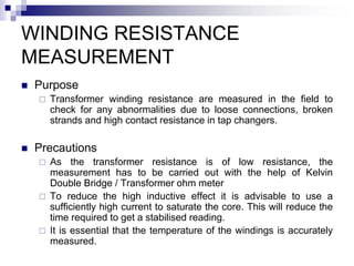
TESTING OF
TRANSFORMERS
 Tests on Bushing CTs
 IR , Continuity and polarity, Ratio and Magnetization test
 IR measurements
 Ratio test
 Vector group test
 Floating Neutral point measurement
 Magnetization current test
 Magnetic balance test ( for 3 phase unit )
 C & Tan delta measurement of bushings and windings
TESTING OF TRANSFORMERS
contd…
 Winding resistance measurement
 Tests on OLTC and Cooler controls
 Alarm and trip tests
 Core Isolation test
 Testing of oil for DGA & other parameters
 Oil filling , oil circulation and air venting
TESTS ON BUSHING CTs
 Purpose
 These tests are carried out to ascertain the healthiness of bushing
current transformer at the time of erection and in service.
 Insulation resistance measurement
 Insulation-resistance tests is performed between CT windings and
to ground using a Megger. Test voltage will be 500 V. the neutral
ground must be removed and CT isolated from its burden. Accepted
min. IR value is 1 M-Ohm
 Polarity Test
 DC Kick/Flick Test: This is the tried and true method for testing CT
polarity. For this test, a dc battery pack ( 6-10 V), a dc voltmeter or
ammeter (preferably analog), and test leads are required. This
method is a quick and easy test for polarity The steps of the dc
kick/flick test are as follows:
 Connect the battery pack to the primary of bushing CT and
momentary deflection of pointer of voltmeter ( centre Zero )
connected to secondary is noted.
Tests on Bushing CTs contd…
 Closely watch the needle or analog scale of the voltmeter. It
should jump in the positive direction. This happens in a
fraction of a second, so the meter must be monitored very
closely. If the voltmeter kicks in the positive direction, the
polarity marks are correct. If it kicks in the negative direction,
the polarity marks are incorrect.
Primary and secondary leads are said to have same polarity
when at a given instant the current enters the primary lead in
question and leaves the secondary lead in question in the
same direction as though two leads formed a continuous
circuit.
Tests on Bushing CTs contd…
 Ratio test
 The CT ratio test determines the CT accuracy, and the
results should be compared to the accuracy class.The
steps for a ratio-verification test are as follows:
 A suitable voltage, below saturation is applied to the
secondary ( full winding ) and the primary voltage is read
with a high impedance low range voltmeter.
 Connect a voltage source (variable transformer) and
voltmeter across the CT secondary.
 Connect a voltmeter across the CT primary.
Tests on Bushing CTs contd…
 Apply voltage to the CT secondary and
measure the secondary (VM1) and primary
voltages (VM2) simultaneously. Calculate
the ratio between the two voltages (VM1 /
VM2).
 This voltage should match the CT ratio
(primary / secondary). You can repeat the
procedure above for each tap of a multitap
CT, but I prefer to treat the CT taps as I
would an autotransformer. I apply a voltage
across the maximum ratio tap and measure
all remaining taps to a common point.
Tests on Bushing CTs contd…
 Magnetization test
 Some of the following conditions can cause CT
saturation:
 CT secondary burden greater than rated.
 Extremely high current flowing through the
CT (fault current).
 Current flowing through CT primaries with
open-circuit secondaries.
 DC current flowing through either winding.
Tests on Bushing CTs contd…
 The excitation test is used to prove that the CT is not
saturated and will operate within specifications at the
rated burden. It is important to remember when
comparing test results to the burden rating that the
burden rating is a minimum value. The CT could
actually have a higher rating. This happens often in
transformer bushing applications.
 A saturation test is performed by applying ac voltage
to the CT secondary and increasing the voltage in
steps until the CT is in saturation. The test voltage is
slowly decreased to zero to demagnetize the CT.
The test results are plotted on a logarithmic graph
and evaluated based on the transition period
between normal operation and saturation. This
transition is called the knee of the curve and is
directly related to the voltage burden rating of the
CT.
IR MEASUREMENTS
Purpose
 This is the simplest and most widely used test to
check the soundness of transformer insulation.
 This test reveals the condition of insulation i.e
degree of dryness of paper insulation, presence of
any foreign contaminants in oil and also any gross
defect inside the transformer.
 The instrument used is Megohm Meter popularly
known as Megger. IR value measurements of EHV
transformers to be done with 5 KV Megger.
IR MEASUREMENTS contd….
 Safety instructions
The test specimen is discharged by short
circuiting for a period at least four times as
long as the test voltage was applied. Before
bare hand contact , the absence of voltage
shall be confirmed by measurement.
 Precautions
Clean the bushing porcelains by wiping with a
piece of dry cloth.
IR MEASUREMENTS contd…
 Lead wires from the bushing line lead and tank earth
to megger shall be as short as possible without joints
and shall not touch tank or each other.
 Testing procedure
 IR measurements shall be taken between the
windings collectively i.e with all the windings being
connected together and the earthed tank and
between each winding and the tank, the rest of the
windings being earthed. Following measurements are
relevant for auto-transformers and Reactors
IR MEASUREMENTS contd…
 For Auto transformer For Reactor
 HV+IV / E HV / E
 LV / E
 HV+IV / LV
 HV- High Voltage, IV- Intermediate Voltage, LV – Low
Voltage, E- Earth
 Record date and time of measurement sl.no & make of
megger, oil temperature and IR values at intervals of 15
seconds, 1 minute and 10 minutes
IR MEASUREMENTS contd…
 Evaluation of test results
 In air, IR values will be nearly 15-20 times more than
in transformer oil at the same temperature.
 With every 10°C drop in temperature, IR values
increases by approximately 1.5 times i.e. an IR value
of 200 M-ohms at an oil temp. of 40°C is equivalent to
300 M-ohms at 30°C.
 Following IR values as a thumbrule may be
considered as the minimum satisfactory values at
30°C ( one minute measurements ) at the time of
commissioning
IR MEASUREMENTS contd…
 Rated Voltage class Minumum desired
 of Winding IR value at 1 min.
 11 KV 300 M-ohms
 33 KV 400 M-ohms
 66 KV & above 500 M-ohms
IR MEASUREMENTS contd…
 Polarisation Index
 It is the ratio of the 10 min to 1 min readings.
 Polarisation Index Insulation condition
 Less than 1 Dangerous
 1.0 – 1.1 Poor
 1.1 – 1.25 Questionable
 1.25 – 2.0 Fair
 Above 2.0 Good
RATIO TEST
 Purpose
 To determine the turns ratio of transformers.
 Turns ratio is the ratio of the number of turns in a
higher winding to that in a lower winding.
 PRECAUTIONS
 The voltage should be applied only in the High
voltage winding in order to avoid unsafe voltage.
Ratio test contd…
 Testing procedures
 Keep the tap position in the lowest position and IV and LV
terminals open.
 Apply 3 phase 415 V supply on HV terminals
 Measure voltages applied on each phase ( Phase-Phase) on HV
and IV terminals simultaneously
 Repeat above steps for each of the tap position separately
 Repeat above steps after interchanging the voltmeters of HV and
IV windings and then average the readings for final calculation of
ratio.
 The above test can also be performed by Transformer turns
ration meter(TTR)
 Two windings on one phase of a transformer are connected to
the instrument and in the internal bridge elements are varied to
produce a null indication on the detector
Ratio test contd…
 Evaluation of results
 The turns ratio tolerance should be within 0.5%
 Out of tolerance ratio may be symptomatic of shorted
turns especially if there is an associated high
excitation current.
 Ratio measurements must be made on all taps to
confirm the proper alignment and operation of the tap
changers.
 Open turns in the excited winding will be indicated
with very low exciting current and no output voltage
VECTOR GROUP TEST
 Purpose
 To determine the phase relationship and polarity of transformers.
 Testing procedures
 Connect Neutral point and LV phase with earth.
 Join 1R1 of HV and 3R1 of tertiary.
 Apply 415 V 3 phase supply to HV terminals
 Measure voltage across the following terminals
 1R1 – 1Y1 3Y1 – 1B1 3Y1 - N 2Y1 - N
 1Y1 - 1 B1 3Y1 – 1Y1 1R1 – N 2B1 - N
 1B1 – 1 R1 3R1 – N 2R1 - N
Vector group test contd…
 Evaluation of results
Ensure 2R1 – N = 2Y1 – N = 2B1 – N
Ensure 3R1 – N > 3Y1 – N > 3B1 – N
 3Y1 – 1B1 >3Y1 – 1Y1
The above confirms vector group Y naod 11
FLOATING NEUTRAL POINT
MEASUREMENT
 Purpose
 This test is conducted to ascertain possibility of short circuit in a
winding.
 Precaution
 No winding terminal should be grounded.
 Testing procedure
 Keep the tap in normal position
 Disconnect the transformer neutral from ground.
 Apply 3 phase 415 V in the HV winding and measure voltage
across each of the IV winding and neutral, then neutral and
ground.
 Apply 3 phase 415 V to IV winding and measure voltage across
each of the tertiary winding terminal and neutral, then neutral
and ground.
 Evaluation of test results
 For a healthy transformer the voltage between neutral and
ground should be zero or negligible.
MAGNETISING CURRENT
TEST
 Purpose
 This test is performed to locate defect in magnetic
core structure, shifting of windings, failures in turn to
turn insulation or problems in tap changers.
 Precautions
 This test should be done before DC measurements of
winding resistance to reduce the effect of residual
magnetism. The transformer may be demagnetised
before commencement of magnetising current test.
MAGNETISING CURRENT TEST
contd
 Testing Procedure
 Keep the tap position in the lowest position and IV and LV
terminals open.
 Apply 3 phase 415 V supply on HV terminals.
 Measure the voltages applied on each phase ( phase – phase )
on HV terminals and current in each phase of HV terminal.
 After completion of the above steps , repeat the measurements
in tap position Normal as well as in Highest position.
 Keep the tap position in normal and keep HV and LV terminals
open.
 Apply 3 phase 415 V supply on IV terminals
 Measure phase to phase voltage between the IV terminals and
current on each of the IV terminals.
MAGNETISING CURRENT TEST
contd…
 Evaluation of test results
 The set of readings for current measurements in each
of the tap position should be equal. Un equal currents
shall indicate possible short circuits in winding.
 Results between similar single-phase units should not
vary more than 10%. The test values on the outside
legs should be within 15% of each other and values
for the centre leg should not be more than either
outside for a 3 phase transformer.
 If an out of tolerance reading is experienced while
turns ratio, winding resistance and impedance tests
are normal , residual magnetism should be
suspected.
MAGNETIC BALANCE TEST
 Purpose
This test is conducted to check the imbalance
in the magnetic circuit only in 3 phase X’mers.
 Precautions
No winding terminal should be grounded ,
otherwise results would be erratic and
confusing.
MAGNETIC BALANCE TEST
contd…
 Testing Procedures
Keep the tap in normal tap position
Disconnect the X’mer neutral from ground
Apply single phase 230 V across one phase
of IV winding terminal and neutral ( say V1)
then measure voltage in other two IV
terminals across neutral ( say V2 & V3 ).
Repeat the test for each of the three phases.
Repeat the above test for HV winding also.
MAGNETIC BALANCE TEST
contd…
 Evaluation of results
Ensure that V1 = V2 + V3
Zero voltage or very negligile voltage induced
in other two windings should be investigated.
C AND TAN DELTA
MEASUREMENT( BUSHING)
 Purpose
 Insulation power factor or dissipation factor ( Tan
delta ) and capacitance measurement of bushing
provide an indication of the quality and soundness of
the insulation in the bushing.
 Precautions
 Measurement may be made at low voltages usually
below 10 KV.
 Connection to over head bus at the bushing need to
be removed only if the bus affect the readings
appreciably.
 Porcelain of the bushings shall be clean and dry.
C AND TAN DELTA MEASUREMENT(
BUSHING) contd…
 Tests shall not be carried out when there is condensation on the
porcelain and when the RH is in excess of 80 %.
 Terminals of the bushings of each winding shall be shorted together
using bare braided copper jumper. These jumper shall not be allowed to
sag. Transformer windings not tested shall be grounded.
 Measure and record ambient temperature and relative humidity for
reference.
 Ensure that the test specimen is isolated from other equipments.
 Connect the ground terminal of the test set to a low impedance earth
ground ( to earth mat of the sub-station )
Type Tests
Routine Tests
Special Tests
Tan Delta & Capacitor Measurement
Type Tests
Routine Tests
Special Tests
Tan Delta & Capacitor Measurement
Mains & Commutating Mode
Routine Tests
Special Tests
Tan Delta Testing
For Null Condition
N1 I1 = N2 I2
For Capacitive Current
N1 ICs = N2 ICx
N1  VCs = N2  VCx
Cx = (N1/N2)/Cs
Type Tests
Routine Tests
Special Tests
Tan Delta Measurement of Bushings
Type Tests
Routine Tests
Special Tests
Tan Delta Measurement of Bushings
For C1: Apply 10kV between HV and test tap on UST mode.
For C2: Apply 500 kV between Test tap and Ground with
HV Guarded on GSTg mode
Type Tests
Routine Tests
Special Tests
UST Mode
Earth will be connected to N Point
Hence only CHL will be measured
Type Tests
Routine Tests
Special Tests
GST Mode
Here measurement is made for the
Parallel combination of CH and CHL
Type Tests
Routine Tests
Special Tests
GSTg mode
Here measurement is done for CH
as L is guarded
C & Tan  measurement contd…
 Windings
 For ICTs (2 Winding Transformers), following combination shall
be taken:
 HV+IV& LV in UST mode, both Mains and reverse and average
to be taken to nullify external interference
 HV+IV & Tank (LV to Gnd to Guard ) in GSTg mode
 LV & Tank (LV to Gnd and HV to Guard) in GSTg mode
- For Reactors, the measurement should be done in
HV/Tank+Gnd in GST mode
- For 3 winding transformer, measurement to be made between
each winding and Gnd with one remaining winding guarded and
the second remaoning winding grounded in GSTg test mode
C & Tan  measurement
contd…
 Windings contd.
 The test is performed at 10 KV
 Max. value of Tan  of class A paper insulation , oil
impregnated at 20 ° C should be 0.007.
 Rate of change of Tan and capacitance should be
marginal. Tan should not vary more than 0.001
from previous value. Capacitance value should be
+10%, -5%
 Tan  measurement is temperature dependent and
correction factor should be applied , if
measurement is taken at temperature other than 20
° C.
C & Tan  measurement contd…
 For ICTs :
 Tan delta and Capacitance measurement of windings
should be done in combination of
 HV+IV / LV+TANK+E
 HV+IV+LV / TANK+E
 LV/HV+IV+TANK+E IN GST TEST MODE
 For Reactors
 HV / TANK+E IN GST TEST MODE
WINDING RESISTANCE
MEASUREMENT
 Purpose
 Transformer winding resistance are measured in the field to
check for any abnormalities due to loose connections, broken
strands and high contact resistance in tap changers.
 Precautions
 As the transformer resistance is of low resistance, the
measurement has to be carried out with the help of Kelvin
Double Bridge / Transformer ohm meter
 To reduce the high inductive effect it is advisable to use a
sufficiently high current to saturate the core. This will reduce the
time required to get a stabilised reading.
 It is essential that the temperature of the windings is accurately
measured.
WINDING RESISTANCE
MEASUREMENT contd…
 Testing Procedure
 For star connected auto-transformers the resistance
of the HV side is measured between HV terminal and
IV terminal, then between IV terminal and neutral
 For delta connected windings , such as tertiary
winding of auto transformers, measurement shall be
done between pairs of line terminals and resistance of
winding shall be calculated as per the following
formula
 Resistance per winding = 1.5 x Measured value
 Calculate the resistance at 75° C as per the following
formula
 R 75 = Rt(235+75) / (235+t) Where Rt is the
resistance measured at winding temperature
WINDING RESISTANCE
MEASUREMENT contd…
 Evaluation of test results
Expected deviation for this test at site is 5.0 %
of the factory test value.
The resistance value obtained should be
compared with the factory test value in case
of pre-commissioning and with pre-
commissioning test value in case the test is
carried out during routine maintenance.
OPERATIONAL TEST ON
OLTC
 Purpose
 OLTC are designed to be operated while the transformer is
energised.
 OLTC being a current interrupting device requires periodic
inspection and maintenance.
 The frequency of inspection is based on time in servicem range
of use and number of operations.
 Precautions
 This test shall be carried out during shutdown period under SFT
 Ensure isolation of X’mer for HV and LV side with physical
opening of concerned isolators.
 If tertiary is connected, ensure isolation of the same
TAP CHANGER HAND
OPERATION
 Check hand operation of the tap changer
up and down the full range before
electrical operation.
 Check the continuity during tap changing
operation by connecting an analogue
multimeter across HV & IV bushing and
change the tap positions from maximum to
minimum.
TAP CHANGER HAND
OPERATION contd…
 Check that the tap changer moves one tap at a time by pushing R or
L push button.
 Check accurate indication of mechanical position indicator in all
positions. Also check the remote instrument operates in the same
sequence to the same accuracy.
 Check the operation of tap changer incomplete alarm including the
flag relay by winding the unit by hand half way through a tap
change.
 Check the tap changer counter operates correctly and record the
readings.
 Check the remote indication and control facility is proved to the
outgoing terminals of the marshalling kiosk.
 Check the out of step relay operation by moving one tap changer in
the three phase bank to one position out of step with other two. The
tap changer faulty alarm should come. Repeat for other two phases.
Operational checks on Cooler
 Cooler Control Switch
 Auto control from WTI
 Time delay for pump
 Pump failure alarm
 Auto start of standby pump
 Stand pump indication
 Cooler fail alarm
 Fuse rating correct
 Differential pressure alarm
VIBRATION MEASUREMENT ON
SHUNT REACTOR
 Purpose
 To measure the vibrations of core / coil assembly in the tank of
the reactor. Movement of cor-coil assembly and shielding
structure caused by the time varying magnetic forces results in
vibrationof the tank and ancilliary equipment
 Testing method
 Minimum no. of readings required shall be 48.
 Each of the four sides of the SR tank shall be divided in to 12
rectangular areas of approximately the same size. These areas
are suitably marked and numbered for reference. Vibration
readings are measured at these points and recorded.
 Evaluation of test results
 The average amplitude of all local max.points shall not exceed
60 µm . The max. amplitude within any rectangular area shall not
exceed 200 µm.
Protection & Alarm checks
Check for correct operation of protection by sorting contacts at MB / relay and
appearance of alarm at control panel in C.R.:
 Buchholz relay/ OSR of Main tank / OLTC
 WTI/ OTI
 PRD
 Low oil level in conservator
 Tap change incomplete
 Cooler fan/ pump fail
CORE ISOLATION TEST
 Purpose
 This test is recommended before the unit is placed in service or
following modifications to the transformer that could affect the integrity
of its core insulation and at other times during a major inspection.
 Testing procedure
 The ground connection terminals for the X’mer or reactor active part are
located in a box.
 The terminal box contains a terminal block with three terminals.
 CL – connected to core laminations
 CC – connected to core clamps
 G – connected to ground ( the tank )
 For core insulation ground test , disconnect the closing link that
connects the two terminals CL-G. Apply 2.5 KV direct voltage between
CL and CC+G. The tank shall be grounded during the test.
 The insulation value after 1 minute test time shall be minimum 100 M-
ohms for service transformers and more than 1000 M-ohms for new
transformers.
DGA & Oil parameters tests
 OIL SAMPLE TO BE TAKEN FOR DGA AS PER
FOLLOWING FREQUENCY
 BEFORE COMMISSIONING
 24 HOURS AFTER 1ST CHARGING
 15 DAYS AFTER 1ST CHARGING
 ONE MONTH AFTER 1ST CHARGING
 3 MONTHS AFTER 1ST CHARGING
 THEREAFTER EVERY SIX MONTHS
Oil Parameters before energisation
 Prior to energisation of transformer, the oil sample
shall be tested for following properties & acceptance
norms:
 1. BDV (kV rms)-60 kV (Min.)
 2. Moisture content -15 ppm (Max.)
 3. Tan delta at 90 ºC-0.05 (Max.)
 4. Resisitivity at 90 ºC-1*10 -cm (Min.)
 5. Interfacial Tension-0.03 N/m (Min.)

Testing of transformers and reactors.ppt

  • 1.
    TESTING OF TRANSFORMERS  Testson Bushing CTs  IR , Continuity and polarity, Ratio and Magnetization test  IR measurements  Ratio test  Vector group test  Floating Neutral point measurement  Magnetization current test  Magnetic balance test ( for 3 phase unit )  C & Tan delta measurement of bushings and windings
  • 2.
    TESTING OF TRANSFORMERS contd… Winding resistance measurement  Tests on OLTC and Cooler controls  Alarm and trip tests  Core Isolation test  Testing of oil for DGA & other parameters  Oil filling , oil circulation and air venting
  • 3.
    TESTS ON BUSHINGCTs  Purpose  These tests are carried out to ascertain the healthiness of bushing current transformer at the time of erection and in service.  Insulation resistance measurement  Insulation-resistance tests is performed between CT windings and to ground using a Megger. Test voltage will be 500 V. the neutral ground must be removed and CT isolated from its burden. Accepted min. IR value is 1 M-Ohm  Polarity Test  DC Kick/Flick Test: This is the tried and true method for testing CT polarity. For this test, a dc battery pack ( 6-10 V), a dc voltmeter or ammeter (preferably analog), and test leads are required. This method is a quick and easy test for polarity The steps of the dc kick/flick test are as follows:  Connect the battery pack to the primary of bushing CT and momentary deflection of pointer of voltmeter ( centre Zero ) connected to secondary is noted.
  • 4.
    Tests on BushingCTs contd…  Closely watch the needle or analog scale of the voltmeter. It should jump in the positive direction. This happens in a fraction of a second, so the meter must be monitored very closely. If the voltmeter kicks in the positive direction, the polarity marks are correct. If it kicks in the negative direction, the polarity marks are incorrect. Primary and secondary leads are said to have same polarity when at a given instant the current enters the primary lead in question and leaves the secondary lead in question in the same direction as though two leads formed a continuous circuit.
  • 5.
    Tests on BushingCTs contd…  Ratio test  The CT ratio test determines the CT accuracy, and the results should be compared to the accuracy class.The steps for a ratio-verification test are as follows:  A suitable voltage, below saturation is applied to the secondary ( full winding ) and the primary voltage is read with a high impedance low range voltmeter.  Connect a voltage source (variable transformer) and voltmeter across the CT secondary.  Connect a voltmeter across the CT primary.
  • 6.
    Tests on BushingCTs contd…  Apply voltage to the CT secondary and measure the secondary (VM1) and primary voltages (VM2) simultaneously. Calculate the ratio between the two voltages (VM1 / VM2).  This voltage should match the CT ratio (primary / secondary). You can repeat the procedure above for each tap of a multitap CT, but I prefer to treat the CT taps as I would an autotransformer. I apply a voltage across the maximum ratio tap and measure all remaining taps to a common point.
  • 7.
    Tests on BushingCTs contd…  Magnetization test  Some of the following conditions can cause CT saturation:  CT secondary burden greater than rated.  Extremely high current flowing through the CT (fault current).  Current flowing through CT primaries with open-circuit secondaries.  DC current flowing through either winding.
  • 8.
    Tests on BushingCTs contd…  The excitation test is used to prove that the CT is not saturated and will operate within specifications at the rated burden. It is important to remember when comparing test results to the burden rating that the burden rating is a minimum value. The CT could actually have a higher rating. This happens often in transformer bushing applications.  A saturation test is performed by applying ac voltage to the CT secondary and increasing the voltage in steps until the CT is in saturation. The test voltage is slowly decreased to zero to demagnetize the CT. The test results are plotted on a logarithmic graph and evaluated based on the transition period between normal operation and saturation. This transition is called the knee of the curve and is directly related to the voltage burden rating of the CT.
  • 9.
    IR MEASUREMENTS Purpose  Thisis the simplest and most widely used test to check the soundness of transformer insulation.  This test reveals the condition of insulation i.e degree of dryness of paper insulation, presence of any foreign contaminants in oil and also any gross defect inside the transformer.  The instrument used is Megohm Meter popularly known as Megger. IR value measurements of EHV transformers to be done with 5 KV Megger.
  • 10.
    IR MEASUREMENTS contd…. Safety instructions The test specimen is discharged by short circuiting for a period at least four times as long as the test voltage was applied. Before bare hand contact , the absence of voltage shall be confirmed by measurement.  Precautions Clean the bushing porcelains by wiping with a piece of dry cloth.
  • 11.
    IR MEASUREMENTS contd… Lead wires from the bushing line lead and tank earth to megger shall be as short as possible without joints and shall not touch tank or each other.  Testing procedure  IR measurements shall be taken between the windings collectively i.e with all the windings being connected together and the earthed tank and between each winding and the tank, the rest of the windings being earthed. Following measurements are relevant for auto-transformers and Reactors
  • 12.
    IR MEASUREMENTS contd… For Auto transformer For Reactor  HV+IV / E HV / E  LV / E  HV+IV / LV  HV- High Voltage, IV- Intermediate Voltage, LV – Low Voltage, E- Earth  Record date and time of measurement sl.no & make of megger, oil temperature and IR values at intervals of 15 seconds, 1 minute and 10 minutes
  • 13.
    IR MEASUREMENTS contd… Evaluation of test results  In air, IR values will be nearly 15-20 times more than in transformer oil at the same temperature.  With every 10°C drop in temperature, IR values increases by approximately 1.5 times i.e. an IR value of 200 M-ohms at an oil temp. of 40°C is equivalent to 300 M-ohms at 30°C.  Following IR values as a thumbrule may be considered as the minimum satisfactory values at 30°C ( one minute measurements ) at the time of commissioning
  • 14.
    IR MEASUREMENTS contd… Rated Voltage class Minumum desired  of Winding IR value at 1 min.  11 KV 300 M-ohms  33 KV 400 M-ohms  66 KV & above 500 M-ohms
  • 15.
    IR MEASUREMENTS contd… Polarisation Index  It is the ratio of the 10 min to 1 min readings.  Polarisation Index Insulation condition  Less than 1 Dangerous  1.0 – 1.1 Poor  1.1 – 1.25 Questionable  1.25 – 2.0 Fair  Above 2.0 Good
  • 16.
    RATIO TEST  Purpose To determine the turns ratio of transformers.  Turns ratio is the ratio of the number of turns in a higher winding to that in a lower winding.  PRECAUTIONS  The voltage should be applied only in the High voltage winding in order to avoid unsafe voltage.
  • 17.
    Ratio test contd… Testing procedures  Keep the tap position in the lowest position and IV and LV terminals open.  Apply 3 phase 415 V supply on HV terminals  Measure voltages applied on each phase ( Phase-Phase) on HV and IV terminals simultaneously  Repeat above steps for each of the tap position separately  Repeat above steps after interchanging the voltmeters of HV and IV windings and then average the readings for final calculation of ratio.  The above test can also be performed by Transformer turns ration meter(TTR)  Two windings on one phase of a transformer are connected to the instrument and in the internal bridge elements are varied to produce a null indication on the detector
  • 18.
    Ratio test contd… Evaluation of results  The turns ratio tolerance should be within 0.5%  Out of tolerance ratio may be symptomatic of shorted turns especially if there is an associated high excitation current.  Ratio measurements must be made on all taps to confirm the proper alignment and operation of the tap changers.  Open turns in the excited winding will be indicated with very low exciting current and no output voltage
  • 19.
    VECTOR GROUP TEST Purpose  To determine the phase relationship and polarity of transformers.  Testing procedures  Connect Neutral point and LV phase with earth.  Join 1R1 of HV and 3R1 of tertiary.  Apply 415 V 3 phase supply to HV terminals  Measure voltage across the following terminals  1R1 – 1Y1 3Y1 – 1B1 3Y1 - N 2Y1 - N  1Y1 - 1 B1 3Y1 – 1Y1 1R1 – N 2B1 - N  1B1 – 1 R1 3R1 – N 2R1 - N
  • 20.
    Vector group testcontd…  Evaluation of results Ensure 2R1 – N = 2Y1 – N = 2B1 – N Ensure 3R1 – N > 3Y1 – N > 3B1 – N  3Y1 – 1B1 >3Y1 – 1Y1 The above confirms vector group Y naod 11
  • 21.
    FLOATING NEUTRAL POINT MEASUREMENT Purpose  This test is conducted to ascertain possibility of short circuit in a winding.  Precaution  No winding terminal should be grounded.  Testing procedure  Keep the tap in normal position  Disconnect the transformer neutral from ground.  Apply 3 phase 415 V in the HV winding and measure voltage across each of the IV winding and neutral, then neutral and ground.  Apply 3 phase 415 V to IV winding and measure voltage across each of the tertiary winding terminal and neutral, then neutral and ground.  Evaluation of test results  For a healthy transformer the voltage between neutral and ground should be zero or negligible.
  • 22.
    MAGNETISING CURRENT TEST  Purpose This test is performed to locate defect in magnetic core structure, shifting of windings, failures in turn to turn insulation or problems in tap changers.  Precautions  This test should be done before DC measurements of winding resistance to reduce the effect of residual magnetism. The transformer may be demagnetised before commencement of magnetising current test.
  • 23.
    MAGNETISING CURRENT TEST contd Testing Procedure  Keep the tap position in the lowest position and IV and LV terminals open.  Apply 3 phase 415 V supply on HV terminals.  Measure the voltages applied on each phase ( phase – phase ) on HV terminals and current in each phase of HV terminal.  After completion of the above steps , repeat the measurements in tap position Normal as well as in Highest position.  Keep the tap position in normal and keep HV and LV terminals open.  Apply 3 phase 415 V supply on IV terminals  Measure phase to phase voltage between the IV terminals and current on each of the IV terminals.
  • 24.
    MAGNETISING CURRENT TEST contd… Evaluation of test results  The set of readings for current measurements in each of the tap position should be equal. Un equal currents shall indicate possible short circuits in winding.  Results between similar single-phase units should not vary more than 10%. The test values on the outside legs should be within 15% of each other and values for the centre leg should not be more than either outside for a 3 phase transformer.  If an out of tolerance reading is experienced while turns ratio, winding resistance and impedance tests are normal , residual magnetism should be suspected.
  • 25.
    MAGNETIC BALANCE TEST Purpose This test is conducted to check the imbalance in the magnetic circuit only in 3 phase X’mers.  Precautions No winding terminal should be grounded , otherwise results would be erratic and confusing.
  • 26.
    MAGNETIC BALANCE TEST contd… Testing Procedures Keep the tap in normal tap position Disconnect the X’mer neutral from ground Apply single phase 230 V across one phase of IV winding terminal and neutral ( say V1) then measure voltage in other two IV terminals across neutral ( say V2 & V3 ). Repeat the test for each of the three phases. Repeat the above test for HV winding also.
  • 27.
    MAGNETIC BALANCE TEST contd… Evaluation of results Ensure that V1 = V2 + V3 Zero voltage or very negligile voltage induced in other two windings should be investigated.
  • 28.
    C AND TANDELTA MEASUREMENT( BUSHING)  Purpose  Insulation power factor or dissipation factor ( Tan delta ) and capacitance measurement of bushing provide an indication of the quality and soundness of the insulation in the bushing.  Precautions  Measurement may be made at low voltages usually below 10 KV.  Connection to over head bus at the bushing need to be removed only if the bus affect the readings appreciably.  Porcelain of the bushings shall be clean and dry.
  • 29.
    C AND TANDELTA MEASUREMENT( BUSHING) contd…  Tests shall not be carried out when there is condensation on the porcelain and when the RH is in excess of 80 %.  Terminals of the bushings of each winding shall be shorted together using bare braided copper jumper. These jumper shall not be allowed to sag. Transformer windings not tested shall be grounded.  Measure and record ambient temperature and relative humidity for reference.  Ensure that the test specimen is isolated from other equipments.  Connect the ground terminal of the test set to a low impedance earth ground ( to earth mat of the sub-station )
  • 30.
    Type Tests Routine Tests SpecialTests Tan Delta & Capacitor Measurement
  • 31.
    Type Tests Routine Tests SpecialTests Tan Delta & Capacitor Measurement Mains & Commutating Mode
  • 32.
    Routine Tests Special Tests TanDelta Testing For Null Condition N1 I1 = N2 I2 For Capacitive Current N1 ICs = N2 ICx N1  VCs = N2  VCx Cx = (N1/N2)/Cs
  • 33.
    Type Tests Routine Tests SpecialTests Tan Delta Measurement of Bushings
  • 34.
    Type Tests Routine Tests SpecialTests Tan Delta Measurement of Bushings For C1: Apply 10kV between HV and test tap on UST mode. For C2: Apply 500 kV between Test tap and Ground with HV Guarded on GSTg mode
  • 35.
    Type Tests Routine Tests SpecialTests UST Mode Earth will be connected to N Point Hence only CHL will be measured
  • 36.
    Type Tests Routine Tests SpecialTests GST Mode Here measurement is made for the Parallel combination of CH and CHL
  • 37.
    Type Tests Routine Tests SpecialTests GSTg mode Here measurement is done for CH as L is guarded
  • 38.
    C & Tan measurement contd…  Windings  For ICTs (2 Winding Transformers), following combination shall be taken:  HV+IV& LV in UST mode, both Mains and reverse and average to be taken to nullify external interference  HV+IV & Tank (LV to Gnd to Guard ) in GSTg mode  LV & Tank (LV to Gnd and HV to Guard) in GSTg mode - For Reactors, the measurement should be done in HV/Tank+Gnd in GST mode - For 3 winding transformer, measurement to be made between each winding and Gnd with one remaining winding guarded and the second remaoning winding grounded in GSTg test mode
  • 39.
    C & Tan measurement contd…  Windings contd.  The test is performed at 10 KV  Max. value of Tan  of class A paper insulation , oil impregnated at 20 ° C should be 0.007.  Rate of change of Tan and capacitance should be marginal. Tan should not vary more than 0.001 from previous value. Capacitance value should be +10%, -5%  Tan  measurement is temperature dependent and correction factor should be applied , if measurement is taken at temperature other than 20 ° C.
  • 40.
    C & Tan measurement contd…  For ICTs :  Tan delta and Capacitance measurement of windings should be done in combination of  HV+IV / LV+TANK+E  HV+IV+LV / TANK+E  LV/HV+IV+TANK+E IN GST TEST MODE  For Reactors  HV / TANK+E IN GST TEST MODE
  • 41.
    WINDING RESISTANCE MEASUREMENT  Purpose Transformer winding resistance are measured in the field to check for any abnormalities due to loose connections, broken strands and high contact resistance in tap changers.  Precautions  As the transformer resistance is of low resistance, the measurement has to be carried out with the help of Kelvin Double Bridge / Transformer ohm meter  To reduce the high inductive effect it is advisable to use a sufficiently high current to saturate the core. This will reduce the time required to get a stabilised reading.  It is essential that the temperature of the windings is accurately measured.
  • 42.
    WINDING RESISTANCE MEASUREMENT contd… Testing Procedure  For star connected auto-transformers the resistance of the HV side is measured between HV terminal and IV terminal, then between IV terminal and neutral  For delta connected windings , such as tertiary winding of auto transformers, measurement shall be done between pairs of line terminals and resistance of winding shall be calculated as per the following formula  Resistance per winding = 1.5 x Measured value  Calculate the resistance at 75° C as per the following formula  R 75 = Rt(235+75) / (235+t) Where Rt is the resistance measured at winding temperature
  • 43.
    WINDING RESISTANCE MEASUREMENT contd… Evaluation of test results Expected deviation for this test at site is 5.0 % of the factory test value. The resistance value obtained should be compared with the factory test value in case of pre-commissioning and with pre- commissioning test value in case the test is carried out during routine maintenance.
  • 44.
    OPERATIONAL TEST ON OLTC Purpose  OLTC are designed to be operated while the transformer is energised.  OLTC being a current interrupting device requires periodic inspection and maintenance.  The frequency of inspection is based on time in servicem range of use and number of operations.  Precautions  This test shall be carried out during shutdown period under SFT  Ensure isolation of X’mer for HV and LV side with physical opening of concerned isolators.  If tertiary is connected, ensure isolation of the same
  • 45.
    TAP CHANGER HAND OPERATION Check hand operation of the tap changer up and down the full range before electrical operation.  Check the continuity during tap changing operation by connecting an analogue multimeter across HV & IV bushing and change the tap positions from maximum to minimum.
  • 46.
    TAP CHANGER HAND OPERATIONcontd…  Check that the tap changer moves one tap at a time by pushing R or L push button.  Check accurate indication of mechanical position indicator in all positions. Also check the remote instrument operates in the same sequence to the same accuracy.  Check the operation of tap changer incomplete alarm including the flag relay by winding the unit by hand half way through a tap change.  Check the tap changer counter operates correctly and record the readings.  Check the remote indication and control facility is proved to the outgoing terminals of the marshalling kiosk.  Check the out of step relay operation by moving one tap changer in the three phase bank to one position out of step with other two. The tap changer faulty alarm should come. Repeat for other two phases.
  • 47.
    Operational checks onCooler  Cooler Control Switch  Auto control from WTI  Time delay for pump  Pump failure alarm  Auto start of standby pump  Stand pump indication  Cooler fail alarm  Fuse rating correct  Differential pressure alarm
  • 48.
    VIBRATION MEASUREMENT ON SHUNTREACTOR  Purpose  To measure the vibrations of core / coil assembly in the tank of the reactor. Movement of cor-coil assembly and shielding structure caused by the time varying magnetic forces results in vibrationof the tank and ancilliary equipment  Testing method  Minimum no. of readings required shall be 48.  Each of the four sides of the SR tank shall be divided in to 12 rectangular areas of approximately the same size. These areas are suitably marked and numbered for reference. Vibration readings are measured at these points and recorded.  Evaluation of test results  The average amplitude of all local max.points shall not exceed 60 µm . The max. amplitude within any rectangular area shall not exceed 200 µm.
  • 49.
    Protection & Alarmchecks Check for correct operation of protection by sorting contacts at MB / relay and appearance of alarm at control panel in C.R.:  Buchholz relay/ OSR of Main tank / OLTC  WTI/ OTI  PRD  Low oil level in conservator  Tap change incomplete  Cooler fan/ pump fail
  • 50.
    CORE ISOLATION TEST Purpose  This test is recommended before the unit is placed in service or following modifications to the transformer that could affect the integrity of its core insulation and at other times during a major inspection.  Testing procedure  The ground connection terminals for the X’mer or reactor active part are located in a box.  The terminal box contains a terminal block with three terminals.  CL – connected to core laminations  CC – connected to core clamps  G – connected to ground ( the tank )  For core insulation ground test , disconnect the closing link that connects the two terminals CL-G. Apply 2.5 KV direct voltage between CL and CC+G. The tank shall be grounded during the test.  The insulation value after 1 minute test time shall be minimum 100 M- ohms for service transformers and more than 1000 M-ohms for new transformers.
  • 51.
    DGA & Oilparameters tests  OIL SAMPLE TO BE TAKEN FOR DGA AS PER FOLLOWING FREQUENCY  BEFORE COMMISSIONING  24 HOURS AFTER 1ST CHARGING  15 DAYS AFTER 1ST CHARGING  ONE MONTH AFTER 1ST CHARGING  3 MONTHS AFTER 1ST CHARGING  THEREAFTER EVERY SIX MONTHS
  • 52.
    Oil Parameters beforeenergisation  Prior to energisation of transformer, the oil sample shall be tested for following properties & acceptance norms:  1. BDV (kV rms)-60 kV (Min.)  2. Moisture content -15 ppm (Max.)  3. Tan delta at 90 ºC-0.05 (Max.)  4. Resisitivity at 90 ºC-1*10 -cm (Min.)  5. Interfacial Tension-0.03 N/m (Min.)