
Recommended
Recommended
More Related Content
What's hot
What's hot (20)
Viewers also liked
Viewers also liked (12)
Similar to Insulation Test Hioki 3455
Similar to Insulation Test Hioki 3455 (20)
More from Nanan Ginanjar
Insulation Test Hioki 3455
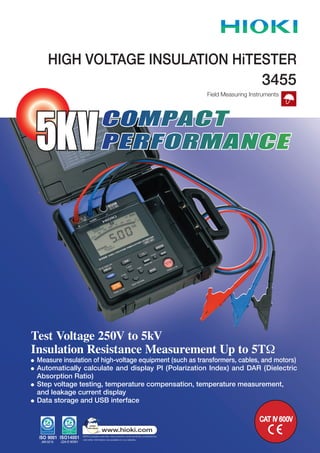
- 1. Test Voltage 250V to 5kV Insulation Resistance Measurement Up to 5TW Measure insulation of high-voltage equipment (such as transformers, cables, and motors) Automatically calculate and display PI (Polarization Index) and DAR (Dielectric Absorption Ratio) Step voltage testing, temperature compensation, temperature measurement, and leakage current display Data storage and USB interface HIGH VOLTAGE INSULATION HiTESTER COMPACT PERFORMANCE5KV Field Measuring Instruments 3455 CAT IV 600V
- 2. 2 n Features Generate Test Voltages Across a Wide Spectrum The 3455 can generate test voltages ranging from 250 V to 5 kV. Settings can be made in steps as fine as 25 V. Very high insulation resistance measurement up to 5 teraohms is possible. Ideal for All Insulation Diagnostic Applications Functions such as automatic calculation and display of PI (Polarization Index) and DAR (Dielectric Absorption Ratio), as well as step voltage test, temperature compensation, temperature measurement, and leakage current display make the 3455 suitable for a variety of diagnostic applications. Data Memory Function The 3455 provides a manual storage function for 100 data and a logging function for 10 data (360 times). The date and time of measurement are also recorded. USB Interface Easily transfer data to a PC via the USB interface using our free PC application software. The software also features a convenient report creation function. Safety Foremost The 3455 complies with Features Generate Test Voltages Across a Wide Spectrum safety regulations for category IV measurements (600 V). A shutter mechanism prevents simultaneous use of measurement terminals and other terminals. Other safety features include a voltage measurement function, high-voltage warning indicator, and auto discharge function. Large, Easy to Read Display The display is backlit and features a logarithmic bar graph as an analog type indicator in addition to the digital readout. Wide Range Test Voltage Settings Actual output voltage > flashes if measurement range was exceeded z Insulation resistance measurement Measurement voltage is selectable from 250 V, 500 V, 1.00 kV, 2.50 kV, and 5.00 kV. More finely graded settings are also possible. When measurement is completed, the unit shows the insulation resistance value, test voltage (setting and actual output), leakage current, DAR, PI, and elapsed time. z Leakage current display When measuring insulation resistance, the instrument can be switched to display leakage current. This is possible before, during, and after measurement. Elapsed time Insulation resistance value Insulation resistance measurement display z Step voltage test In this type of test, the voltage is gradually raised and the insulation resistance and leakage current change is measured. Two different step settings are available: 500 V→ 1 kV → 1.5 kV → 2 kV → 2.5 kV and 1 kV → 2 kV → 3 kV → 4 kV →5 kV. The test time for each step can also be selected. Step1 Step2 Step3 Step4 Step5 5kV 4kV 3kV 2kV 1kV Measurement completed 1 2 3 4 5 minutes n Primary Measurement Functions STEP 5.0 kV step voltage test Display of leakage current during measurement Actual output voltage Insulation resistance value > flashes if less than 1 nA Elapsed time leakage current value
- 3. 3 Response time: n Leakage Current Measurement range: Current range and accuracy: Response time: n Voltage Measurement range: Frequency: Accuracy: Input impedance: Response time: n Temperature Measurement range and Accuracy: Response time: 15s max. (from measurement start to until guaranteed accuracy display, no averaging) (current measurement with test voltage being generated) 1.00nA to 1.20mA 15 s max. (from measurement start to until guaranteed accuracy display, no averaging) (temperature and humidity range for guaranteed accuracy 23±5 ˚C, max. 90%rh, no condensation) DC ±50V to ±1.00kV , AC 50V to 750V DC/ 50Hz/ 60Hz ±5%rdg. ±5dgt. (for DC, absolute values of 1.01 kV and above are out of guaranteed accuracy range) Approx. 10 MW 3 s or less When using the temperature sensor 9631-05, accuracy is guaranteed only for 0.0 - 40.0 ˚C range Approx. 100 s, including response of temperature sensor models 9631-01 to 9631-05 (reference value, time until a 90% value of a temperature change is shown) Current range Measurement range Accuracy 10nA 1.00nA to 9.99nA ±15%rdg. ±1nA 100nA 9.0nA to 99.9nA ± 15%rdg. ±5dgt. 1000nA 90nA to 999nA ±2.5%rdg. ±5dgt. 10µA 0.90µA to 9.99µA ±2.5%rdg. ±5dgt. 100µA 9.0µA to 99.9µA ±2.5%rdg. ±5dgt. 1mA 90µA to 999µA, 0.90mA to 1.20mA ±2.5%rdg. ±5dgt. (auto range, temperature and humidity range for guaranteed accuracy 0 to 28˚C, max. 90%rh, no condensation) Measurement range Accuracy –10.0˚C to –0.1˚C ±1.5˚C 0.0˚C to 40.0˚C ±1.0˚C 40.1˚C to 70.0˚C ±1.5˚C n Measurement Items: n Insulation Resistance Test voltage: Setting: Measurement current: Short-circuit current: Output voltage Monitor function: Measurement range: Resistance range: (auto range) Insulation resistance, leakage current, voltage, temperature 250V to 5.00kV DC Preset test voltages: 250 V, 500 V, 1 kV, 2.5 kV, 5 kV Fine adjustment: possible in 25 V steps between 250 V and 1 kV and in 100 V steps between 1 and 5 kV Applies only when the measured resistance is equal to or higher than the value gained from dividing the test voltage (setting voltage) by the rated measurement current. Output voltage is not guaranteed if measured resistance is lower than [test voltage/rated measurement current]. Rated measurement current tolerance: -0%, +10% 2 mA or less Display range: 0 to 999 V, 0.98 to 5.50 kV Monitor accuracy: ± 5% rdg. ± 5 dgt. Measurement range Accuracy Up to [Test voltage / Resistance measurable at 100 nA] ±5%rdg.±5dgt. [Test voltage / Resistance measurable at 100 nA] to 500 GW ±20%rdg.±5dgt. 501GW to 5.00TW ±30%rdg.±50dgt. Resistance range Measurement range 10MW 0.00MW to 9.99MW 100MW 9.0MW to 99.9MW 1000MW 90MW to 999MW 10GW 0.90GW to 9.99GW 100GW 9.0GW to 99.9GW 1000GW 90GW to 999GW 5TW 0.90TW to 5.00TW Test voltage Measurement range 250 V 0.00MW to 250GW 500 V 0.00MW to 500GW 1 kV 0.00MW to 1.00TW 2.5 kV 0.00MW to 2.50TW 5 kV 0.00MW to 5.00TW Test voltage Measurement current 250V to 1.00kV 1mA 1.10kV to 2.50kV 0.5mA 2.60kV to 5.00kV 0.25mA (temperature and humidity range for guaranteed accuracy 0 to 28˚C, max. 90%rh, no condensation) 250V 500V 1kV 2.5kV 5kV 5.00TΩ 2.50TΩ 1.00TΩ 500GΩ 250GΩ 100GΩ 50.0GΩ 25.0GΩ 10.0GΩ 5.00GΩ 2.50GΩ 1.00GΩ 100MΩ 10.0MΩ 1.00MΩ 0.00MΩ ±30%rdg. ±50dgt. ±20%rdg. ±5dgt. ±5%rdg. ±5dgt. MakeCompleteDiagnosticTestsofTransformers,Cables,MotorsandOtherEquipment n Specifications Accuracy: Resistance range accuracy z PI and DAR display PI: Polarization Index DAR: Dielectric Absorption Ratio The PI and DAR values which are used as an evaluation standard for insulation are automatically calculated. With the insulation resistance measurement start point as reference, the calculation is performed as follows, using two resistance values obtained at a prescribed time interval. resistance value 10 min after start Formulas : PI= resistance value 1 min after start resistance value 1 min after start DAR 1min/15s = resistance value 15 sec after start resistance value 1 min after start DAR 1min/30s = resistance value 30 sec after start Measurement time Right: first measurement Left: second measurement DAR value Resistance value Right: first measurement value Left: second measurement value Measurement time First : 1 min ; Second : 10 min PI value Resistance value Right: first measurement 30.0 GW Left: second measurement 60.0 GW Insulationresistance Test voltage (setting value)
- 4. 4 HEAD OFFICE : 81 Koizumi, Ueda, Nagano, 386-1192, Japan TEL +81-268-28-0562 / FAX +81-268-28-0568 E-mail: os-com@hioki.co.jp HIOKI USA CORPORATION : 6 Corporate Drive, Cranbury, NJ 08512 USA TEL +1-609-409-9109 / FAX +1-609-409-9108 E-mail: hioki@hiokiusa.com DISTRIBUTED BY All information correct as of Jul. 13, 2009. All specifications are subject to change without notice. 3455E4-97M-05K Printed in Japan HIOKI (Shanghai) Sales & Trading Co., Ltd. : 1608-1610 Shanghai Times Square Office, 93 Huai Hai Zhong Road, Shanghai, P.R.China POSTCODE: 200021 TEL +86-21-6391-0090/0092 FAX +86-21-6391-0360 E-mail: info-sh@hioki.com.cn Beijing Office : A-2602 Freetown, 58 Dong San Huan Nan Road Beijing, P.R.China POSTCODE: 100022 TEL +86-10-5867-4080/4081 FAX +86-10-5867-4090 E-mail: info-bj@hioki.com.cn Guangzhou Office : Room A-3206, Victory PlazaServices Center, No.103, Tiyuxi Road, Guangzhou, P.R.China POSTCODE:510620 TEL +86-20-38392673/2676 FAX +86-20-38392679 E-mail: info-gz@hioki.com.cn n Insulation Diagnosis Temperature compensation: PI/DAR display: Step voltage test: nSupplementaryFunctions Data memory: Communication: Other items: Result converted to insulation resistance at reference temperature. 10 different temperature compensation tables can be selected, according to insulation material of measurement object. Reference temperature: 20˚C or 40˚C by default, setting can be changed. PI: Polarization Index DAR: Dielectric Absorption Ratio After insulation resistance measurement has started, calculation is performed using two resistance values obtained at prescribed time intervals. Measurement of insulation resistance while raising voltage at specific intervals. Two voltage step patterns can be selected. STEP 2.5kV : 500V→1kV→1.5kV→2kV→2.5kV STEP 5kV : 1kV→2kV→3kV→4kV→5kV Voltage application time for each step: 30 s./1/2/5 m. Manual recording: store up to 100 data , Data type: standard measurement data/ temperature compensation data/step voltage test data, Data logging: store measurement value at preset intervals, available for insulation resistance measurement only, Number of data: 10, Number of logging instances: 360 times per data, Recording interval: 15/30 s /1/2/5m, Data content: date, time, measurement interval, temperature, set voltage, actual output voltage × times, resistance × times, Additional functions: write mode, read mode, all clear, selective clear, overwrite Interface: USB ver 2.0 (full speed) PC application software: transfer of memory data from 3455 to computer, data display, create graph, 3455 items that can be set/changed from computer: date, time, PI time, step time for step voltage test, report function Temperature/humidity value input, timer, elapsed time display, clock, averaging, data hold, auto discharge, active voltage warning indication, hot conductor warning indication, LCD backlight, auto power-off, buzzer n General Specifications Operating temp. , humidity: Storage temp. , humidity: Guaranteed accuracy period: Operating environment: Measurement method: A/D conversion: Display: Indication: Display update rate: Power supply: Max. power consumption: Continuous operation time: (reference value) Max. input voltage: Max.rated voltage to ground: Withstand voltage: Dimensions & Mass: Applicable standards: Accessories: Options: 0 to 40˚C, max90%rh (no condensation) 10 to 40˚C, max. 80%rh for battery pack charging -10 to 50˚C, max 90%rh (no condensation) 1 year Indoors, up to 2000 m ASL DC voltage application method (insulation resistance), average value rectification method (voltage) Double integral method LCD, with backlight Numeric: up to 999, Bar graph: insulation resistance only, range 0 to 1 TΩ Insulation resistance/leakage current: 1 time/second (0.25 times/second when using averaging) Output voltage monitor: 2 times/second Voltage measurement: 4 times/second Temperature measurement: 1 time/second LR6 (AA) alkaline battery × 6 Battery pack 9459: 7.2 V DC (rechargeable, Ni-MH) AC adapter 9753: rated input voltage 100 to 240 V AC, rated output15VA 15 VA (using AC adapter), 6 VA (using batteries or battery pack) (5 kV generated, +/- terminals open, backlight off) approx. 5 hours (with alkaline batteries) approx. 9 hours (with battery pack 9459 ) AC750Vrms, DC1000V 600Vrms(CATIV) , 1000Vrms (CATIII) 6880 V AC, 15 sec. 260(W) × 250.6(H) × 119.5(D) mm, 2.8kg Safety: EN61010-1:2001, EN61010-031:2002 EMC:EN61326:1997+A1:1998+A2:2001 EN61000-3-2:2000 EN61000-3-3:1995+A1:2001 TEST LEAD (RED) 9750-01 × 1, TEST LEAD (BLACK) 9750-02 × 1, TEST LEAD (BLUE, GUARD) 9750-03 × 1, ALLIGATOR CLIP (RED) 9751-01 × 1, ALLIGATOR CLIP (BLACK) 9751- 02 × 1, ALLIGATOR CLIP (BLUE, GUARD) 9751- 03 × 1, LR6 (size AA) battery × 6, USB CABLE × 1, CD-R (Data Analysis Software for 3455) × 1 TEMPERATURE SENSOR 9631-01 (Thermistor, Molded type, Approx. 1 m) TEMPERATURE SENSOR 9631-05 (Thermistor, Molded type, Approx. 6 cm) TEST LEAD 9750-11 (Red, Approx. 10 m) TEST LEAD 9750-12 (Black, Approx. 10 m) TEST LEAD 9750-13 (Blue, Approx. 10 m, GUARD) BATTERY PACK 9459 AC ADAPTER 9753 n Specifications TEST LEAD 9750 ALLIGATOR CLIP 9751 TEMPERATURE SENSOR 9631-01 Molded plastic, thermistor type TEMPERATURE SENSOR 9631-05 Molded plastic, thermistor type AC ADAPTER 9753BATTERY PACK 9459