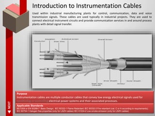
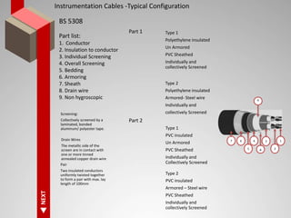
Instrumentation - Cables
GSS Srinivas
Introduction
to Cables
General
Specification
BS 5308
Conductor Insulation
and Jacket
Shield Armoring Selection
of cable
NEXT
Introduction to Instrumentation Cables
Used within industrial manufacturing plants for control, communication, data and voice
transmission signals. These cables are used typically in industrial projects. They are used to
connect electrical instrument circuits and provide communication services in and around process
plants with detail signal transfer.
Purpose
Instrumentation cables are multiple conductor cables that convey low energy electrical signals used for
electrical power systems and their associated processes.
Applicable Standards
BS 5308 or EN 50288-7 Basic Design; IEC 60332-1 Flame Retardant; IEC 60332-3 Fire retardant (cat. C or A according to requirements);
IEC 60754-1 Halogen free properties (only for LSZH cables) IEC 61034-2 Low smoke emission (only for LSZH cables)
NEXT
Instrumentation Cables -Typical Configuration
BS 5308
Part list:
1. Conductor
2. Insulation to conductor
3. Individual Screening
4. Overall Screening
5. Bedding
6. Armoring
7. Sheath
8. Drain wire
9. Non hygroscopic
Type 1
Polyethylene insulated
Un Armored
PVC Sheathed
Individually and
collectively Screened
Part 1
Type 2
Polyethylene insulated
Armored- Steel wire
Individually and
collectively Screened
Type 1
PVC insulated
Un Armored
PVC Sheathed
Individually and
Collectively Screened
Type 2
PVC insulated
Armored – Steel wire
PVC Sheathed
Individually and
collectively Screened
Part 2
Screening:
Collectively screened by a
laminated, bonded
aluminum/ polyester tape.
Drain Wires
The metallic side of the
screen are in contact with
one or more tinned
annealed copper drain wire
Pair
Two insulated conductors
uniformly twisted together
to form a pair with max. lay
length of 100mm
7 6
5
4 3
2
1
8
6
NEXT
Conductors
For instrumentation cables conductors are generally
plain annealed electrolytic copper wire for signal
transmission or special alloy, for thermocouple
/compensating cables. Conductors can generally be
according to EN 60288: class 1 (U) Solid, class 2
(R ) stranded and class 5 (F) flexible
Type of conductors are chosen according to electrical
characteristics, required flexibility, type of connection
systems or specific installation conditions, for
example:
 Class1 solid conductor is preferable for
permanent installation, crimping termination,
 In presence of vibration or movement or reduced
bending radius is preferable class 5 flexible
conductor,
 In presence of corrosive atmosphere, high
temperature or to facilitate the soldering is
preferable tinned conductor.
Conductor
Size
BS EN 60228
Stranding
Bare or Tinned
NEXT
Conductors – Class 1, Class 2 and Class 5&6
Plain Or Metal coated annealed
Wire Coatings:
Applied on the conductors to prevent some insulations from attacking or adhering to copper. Also
helps in soldering and prevents deterioration of copper at high temperatures
Annealing:
A process in which the conductor is heated to over 700 deg F and allowed to cool. This will allow
conductors to bent without breaking, remove stiffness and improve flexibility.
Wire Bars:
Approx. 200 pound billet of cu, roughly
54” long X 3-7/8” wide X 3-5/8” high
used as the feedstock for making the
rod
Rods
A 5/16” or 3/8” dia. rod
drawn from wire bars to
make solid conductors &
individual strands
Stranding
Twisting together small
wires to form a single
conductor. Provide
flexibility, ease of handling
and vibration resistance
Bunch Strand
(ASTM B-174)
A conductor formed by
simple twisting in one
direction of many small
wires. Used in flexible
cords, flexible control cables
and flexible lead wires
Concentric Strand
( ASTM B 8)
A conductor is formed as a
layer with 7,19,37,61 or 91
wires. Normally adjacent
layers are reversed
direction. Control cables
favor 7 and 19 wires.
Rope Lay – Bunch
Stranded members and
Concentric stranded
members
(ASTM B-172&3)
7 or 19 strands form a
conductor. Used in portable
power cables and welding
cables
NEXT
Insulation and Jacket
Insulation applied over conductors for electrical isolation between conductors or from ground
Jacket applied over conductor insulation or cable core for mechanical, chemical or electrical protection
01
02
03
04
05
06
07
08
Size
Electrical
Physical
Chemical Resistance
Environmental Conditions
Service life
Reliability
Flexibility
Wall Thickness
Capacitance,
Attenuation, velocity
of propagation,
Dielectric Strength,
working voltage and
Dielectric constant
Elongation, Tensile Strength,
Temperature rating ,
Flexibility, Flammability,
Resistance, Specific gravity
Chemicals can destroy
cable materials.
Extreme temperatures
brittle at low and soft at
high. Vaccum leaches oils
out of cables. Radiation
cause damage to cables
Ideal cable system should
be engineered to last the
life of the product in any
environmentligula
Ability of a cable to bend
09 Radiation resistance
10
Smoke Generation and Flame
Resistance
Ability of a cable to burn,
construction dependent
and industry standard
apply
Is based on the
both durability and
signal integrity
Radiation index is
the absorbed dose in
Gray (Gy) of the
material after
exposure having 50%
elongation of brake
of its unaged value
at least.
NEXT
Insulation
Working conditions need to be taken into
consideration to choose the right insulation
material.
Material can be divided into thermoplastic
and thermoset (cross linked).
Thermoplastic material are more sensitive to
high temperatures, as material melts at the
increase of temperature, while thermoset,
due to stable polymeric chain bonds are
more resistant to temperature and
deformation.
Most popular insulations are PE and PVC for
general installation conditions and LSZH
thermoplastic materials (low smoke zero
halogen).
Other class includes, XLPE, silicone rubber,
other rubbers such as EPR, HEPR, EVA.
Special techno polymer can be used in case
of specific installation condition, such as
fluoro- polymer or techno-polymer materials.
For fire resistant cables two types of
insulation are used: silicone or mica tape
plus XLPE (or other thermoset compounds).
Insulation
Type
BS 6234/50363/7655
Wall Thickness
Temperature
Voltage
NEXT
Screening
Electrostatic noise can be
reduced by screening around the
cable, around each pair or both
Magnetic noise can be reduced by
increasing distance between cable
and offending power cable and
screening the cable
Screening
Communicati
on Cable
Prevent Noise Interface
Surge Protection
Lighting Protection
Control Cable
Provide Circuit Isolation
Prevent Noise Interface
Surge Protection
Contain Intelligence
High Voltage
Cable
Prevent Corona
Surge Protection
Fault Path Provision
Shield
Electro Static Screen (Grounded at one end)
Metal Tape
A flat Metal Tape
applied with
overlap around
pairs cable core or
inner jacket.Tape,
Al or Cu 75μm
thick
Metal Tape
with Drain
Wire
Copper
Drain Wire
Metal
Laminate
and Drain
Wire
A flat polyester
supported foil tape,
applied with
overlap, around
pairs, triples, etc.,
cable core, or inner
jacket. A drain wire
is normally used
with this type of
shield for ease of
terminating.
Conducting
Plastic and
Drain Wire
Drain Wire
& Semi
conducting
PVC or PE
Sheath
Metal
Braid
A double serving of
uninsulated wires
interlocking in a two
over-two under
pattern. The second
serving is applied in
the reverse direction
of the first
Magnetic Screen (Grounded at both ends)
Copper
Tapes
Copper
Tape
overlap
intrinsic
screening
factor 0.95
Copper
and Steel
Tapes
Cu and Mild
Steel tape
Intrinsic
screening
factor 0.9
Steel Tape
Armored
Cable
Lead or
Moisture
Sheath with
two layers
of Steel
Armour
tape, IS
factor 0.4
to 0.5
Aluminum
and Steel
Tape
Screen
Moisture
barrier, Al
wire/strip,
two layers
of steel
tape, IS
factor 0.06
NEXT
Screening
■ Cross-talk from adjacent pairs or triples;
■ Interference induced by external source
Aluminum /polyester tape with a tinned
copper drain wire, the most popular
construction. Aluminum /polyester or
copper/polyester tapes normally have a total
thickness from 25 to 100 μm, according to
standards and are wrapped with an overlap >
125% to assure a full coverage even in case
of bending.
Bare copper braid for electromagnetic
interference or when the cable is subject to
movements.Tinned copper braid for
electromagnetic interference in presence of
corrosive atmosphere or high temperature.
Copper braid normally has a coverage from
80% to 95%. This type of screen presents a
lower electrical resistance, a very good
protection also to electromagnetic noises and
a higher mechanical resistance compared to
aluminum /polyester tape.
Screening
Type
Overlap
Coverage
Isolation
In continuous contact with metallic side there is
a drain wire, normally tinned copper, 0.5 sq
mm, stranded or solid. Screens can be applied
to each pair/triples (individual screen) and/or
on the bundle of the cable (overall screen).
NEXT
Basic Design BS 5308 or EN 50288 - 7
Armoring
Metallic armor are used when cables have to be installed
direct buried, or if mechanical protection is required.
■ Required tensile load
■ Expected pressure on cable during service
■ Protection against rodent
■ Protection against accidental damage
■ Minimum required bending radius.
SWA: Single layer of galvanized steel wires, with diameters
according to relevant standards, coverage min. 90%. This
armor assures a very good mechanical protection and tensile
strength. An additional counter spiral tape increases solidity, if
required.
GSWB: Galvanized steel wire braid, diameter of wire: 0.20 –
0.25 – 0.30 – 0.40 mm, with coverage of > 80%. It assures a
good mechanical resistance, allowing a lower bending radius
compared to other armor. It is preferable when there is
movement or vibration. For special application is possible to
use stainless steel, tinned copper or special alloy wires.
Armoring
Direction
BS EN 1027
Coverage
Application
GSTA: Galvanized steel tape armor, composed by two tapes
with overlapped edge; thickness of each tape: 0.20 – 0.30 –
0.40 mm, according to cable diameter. It grants a coverage >
100%. Very good crush resistance, but fair tensile strength.
Brass tape of minimum thickness 0.075 mm can be used for
special applications.
GSFA: Galvanized steel flat armor. It is composed by flat
wire of thickness 0.6 mm or 0.8 mm, it is similar to SWA, but
with higher mechanical protection.
NEXT
Sheath
Many compounds can be used as
internal/external protection of cables.
Working condition need to be considered for
the right choice. PVC, PE and LSZH are the
most popular materials, but we have to
consider that different grades are available to
meet specific working conditions. Anyway the
following conditions have to be evaluated:
 Type of installation (indoor/outdoor, direct
buried…)
 Possible presence of humidity, oil, chemicals…
 Behavior in case of a fire (fire propagation, fire
resistance, emission of gases and smoke…)
 Range of temperature
 UV resistance in case of sun exposure
Screening
Type
Wall Thickness
Temperature
Color
NEXT
Basic Design BS 5308 or EN 50288 - 7
Protection
Protection
In addition to mechanical protections, special
protections can be considered for specific
installations
Moisture barrier
If moisture barrier is specified it shall be applied over
the total cabling of elements and is possible to
choose two alternatives:
Water swellable tapes
Laminated sheath, consisting of a longitudinal
overlapped metallic foil, bonded to an extruded
sheath.
Lead Sheath
It is applied between two other sheaths and is the
best protection against aggressive chemicals. This is
an expensive solution, increases weight and bending
radius. It presents poor vibration resistance and
normally an armor is required to protect it from
crushing.
Cable
Protection
Moisture Barrier
High Pack
It is an alternative to Lead Sheath and is
composed by a longitudinal overlapped
aluminum copolimer coated tape bonded to
HDPE jacket and additional special alloy of
polyamide/polypropylene sheath.
■ Excellent protection against corrosion
and humidity.
■ Excellent impact resistance that in some
cases prevents the use of the armor. This
protection has a lower weight compared to
lead sheath, cables have a smaller
diameter, with a reduction of costs. Hi-Pack
is the right choice to protect the
environment.
Thank you
Some tables below
15
Materials
Insulation
Sheath
Temp.Low
Temp.High
Abrasion
resistance
Oilresistance
Solvent
Resistance
Water
Resistance
Nuclear
radiation
resistance
Flame
retardancy
Flexibility
PVC -40 +105 3 3 2 3 2 3 3
Polyethylene -40 +80 3 2 3 4 2 1 2
Polypropylene -40 +105 4 4 4 4 2 1 2
Nylon -70 +120 4 4 4 2 2 1 2
Polyurethane -40 +80 4 4 2 3 3 3 3
XLPE -60 +90 2 3 3 3 2 1 2
Fluoropolymer FEP -80 +205 2 4 4 4 1 4 2
FP PTFE -80 +260 2 4 4 4 1 4 2
FP PFA -80 +260 2 4 4 4 1 4 2
FP MFA -80 +240 2 4 4 4 1 4 2
FP ETFE -80 +155 2 4 4 4 1 4 2
4. Very Good ; 3. Good ; 2. Fair ; 1. PoorCan be used
16
Materials
Insulation
Sheath
Temp.Low
Temp.High
Abrasion
resistance
Oilresistance
Solvent
Resistance
Water
Resistance
Nuclear
radiation
resistance
Flame
retardancy
Flexibility
FP ECTFE -60 +160 3 4 4 4 3 4 1
Hytrel -40 +80 3 4 4 3 1 1 2
Peek -60 +250 2 4 4 4 4 4 1
Kapton -75 +200 4 4 4 4 4 4 1
Technopolymer
LSZH
-30 +90 2 3 2 4 4 3 2
G10 -40 +90 2 2 1 3 3 3 3
Silicone Rubber -60 +200 2 2 1 3 3 3 4
Thermoplastic
Rubber
-55 +125 4 3 2 3 1 3 4
Neoprene -40 +90 4 3 2 3 2 3 4
EPR -50 +90 3 2 1 3 3 1 3
LSZH -30 +90 2 3 2 3 3 3 2
4. Very Good ; 3. Good ; 2. Fair ; 1. PoorCan be used
Insulation and Jacket Materials Properties
Properties
P= Poor
F= Fair
G= Good
E= Excellent
O = Outstanding
The ratings are based on average
performance of general purpose
compounds. Any given property can
usually be improved by the use of
selective compounding.
Thermoplastic Thermoset
PVC
LowDensityPolyethylene
CellularPolyethylene
High-DensityPolyethylene
Polypropylene
CellularPolypropylene
Polyurethane
Nylon
CPE(ChlorinatedPolyethylene)
PremiumgradePVC
FEP
Tefzel(ETFE)
PTFETeflon
Sole/Kynar
Halar
Neoprene
ChlorosulfonatedPolyethylene
EthylenePropyleneRubber(EP,
EPR,EPDM)
XLPE
CPE(ChlorinatedPolyethylene)
SiliconRubber
Oxidation resistance E E E E E E E E E E O E O O O G E E E E E
Heat resistance G-E G G E E E G E E G-E O E O O O G E E G E O
Oil resistance F G-E G G-E F F E E E F O O E E-O E G G P G G-E F-G
Low-temperature flexibility P-G E E E P P G G E P-G O E O O O F-G F G-E O F O
Weather, Sun resistance G-E E E E E E G E E G O E O E-O O G E E G E O
Ozone resistance E E E E E E E E E E E E O E E E E G G-E O
Abrasion resistance F-G G F E F-G F-G O E E-O F-G E E O E E G G F-G G-E P
Electrical Properties F-G E E E E E P P E G E E E G-E E G E E F-G G
Flame resistance E P P P P P P P E E O G E E E-O G P P G F-G
Nuclear radiation resistance F G-E G G-E F F F G F-G O P-G E P E E F-G E G E G E
Water resistance F-G E E E E E P-G P-F O F E E E E E E G-E G-E G-E G-E
Acid resistance G-E G-E G-E E E E F P-E E G E E E G-E E E G-E G-E E F-G
Alkali resistance G-E G-E G-E E E E F E E G E E E E E E G-E G-E E F-G
Gasoline, Kerosene, etc resistance P G-E G G-E P-F P P-G G E P E E E E E G F P F F P-F
Benzol, toluol etc resistance P-F P P P P-F P P-G G G-E P-F E E E G-E E P-F F F F F P
Degreaser solvents resistance P-F G G G P P P-G G E P-F E E E G E P P-F P F P P-G
Alcohol resistance G-E E E E E E P-G P E G E E E E E F G P E G-E G
Underground Burial P-G G F E E F G P E-O P E E E E E G-E E E E E G
Percentage Oxygen (Typical) 23-42 21 18-30 21 21 17 21 24-29 28-36 38-42 30-32 93 43-45 55 32 34 21 30-40 28-36 21
Dielectric Constant ( Typical) 3.6 - 6 2.3 1.5 2.3 2.2-2.3 2.2-2.3 4-7 3.2-5 12 4.5-6.5 2.6 2.1 7-9 2.6 9-10 8-10 3-3.2 3.4 -5 12 3-4
Thermal Characteristics - Deg C (Min) -30 -50 -40 -50 -10 -55 -40 -20 -100 -190 -40 -30 -30 -30 -40 -60
Thermal Characteristics - Deg C (max) 70 100 70 100 100 80 100 105 150 260 135 80 90 90 100 180
Halogen Content in Typical Insulation and Jacket/Sheath Materials
Material Application Voltage Weight %
PE insulation or Jacket <0.02
XLP insulation 600 V <0.02
XLP insulation 5-35KV <0.02
EPR insulation 5-35KV <0.02
Polyurethane jacket <0.02
EVA jacket <0.02
XLP insulation 600 V 7–13
FR-EPR insulation 9–14
CSPE (insulation grade) 13–16
FR-XLP insulation 11–17
CSPE jacket 16–26
Neoprene jacket 16–18
CPE jacket 14–28
CSPE jacket 18–33
PVC jacket 22–29

Instrumentation cables rev2

  • 1.
  • 2.
    Introduction to Cables General Specification BS 5308 ConductorInsulation and Jacket Shield Armoring Selection of cable
  • 3.
    NEXT Introduction to InstrumentationCables Used within industrial manufacturing plants for control, communication, data and voice transmission signals. These cables are used typically in industrial projects. They are used to connect electrical instrument circuits and provide communication services in and around process plants with detail signal transfer. Purpose Instrumentation cables are multiple conductor cables that convey low energy electrical signals used for electrical power systems and their associated processes. Applicable Standards BS 5308 or EN 50288-7 Basic Design; IEC 60332-1 Flame Retardant; IEC 60332-3 Fire retardant (cat. C or A according to requirements); IEC 60754-1 Halogen free properties (only for LSZH cables) IEC 61034-2 Low smoke emission (only for LSZH cables)
  • 4.
    NEXT Instrumentation Cables -TypicalConfiguration BS 5308 Part list: 1. Conductor 2. Insulation to conductor 3. Individual Screening 4. Overall Screening 5. Bedding 6. Armoring 7. Sheath 8. Drain wire 9. Non hygroscopic Type 1 Polyethylene insulated Un Armored PVC Sheathed Individually and collectively Screened Part 1 Type 2 Polyethylene insulated Armored- Steel wire Individually and collectively Screened Type 1 PVC insulated Un Armored PVC Sheathed Individually and Collectively Screened Type 2 PVC insulated Armored – Steel wire PVC Sheathed Individually and collectively Screened Part 2 Screening: Collectively screened by a laminated, bonded aluminum/ polyester tape. Drain Wires The metallic side of the screen are in contact with one or more tinned annealed copper drain wire Pair Two insulated conductors uniformly twisted together to form a pair with max. lay length of 100mm 7 6 5 4 3 2 1 8 6
  • 5.
    NEXT Conductors For instrumentation cablesconductors are generally plain annealed electrolytic copper wire for signal transmission or special alloy, for thermocouple /compensating cables. Conductors can generally be according to EN 60288: class 1 (U) Solid, class 2 (R ) stranded and class 5 (F) flexible Type of conductors are chosen according to electrical characteristics, required flexibility, type of connection systems or specific installation conditions, for example:  Class1 solid conductor is preferable for permanent installation, crimping termination,  In presence of vibration or movement or reduced bending radius is preferable class 5 flexible conductor,  In presence of corrosive atmosphere, high temperature or to facilitate the soldering is preferable tinned conductor. Conductor Size BS EN 60228 Stranding Bare or Tinned
  • 6.
    NEXT Conductors – Class1, Class 2 and Class 5&6 Plain Or Metal coated annealed Wire Coatings: Applied on the conductors to prevent some insulations from attacking or adhering to copper. Also helps in soldering and prevents deterioration of copper at high temperatures Annealing: A process in which the conductor is heated to over 700 deg F and allowed to cool. This will allow conductors to bent without breaking, remove stiffness and improve flexibility. Wire Bars: Approx. 200 pound billet of cu, roughly 54” long X 3-7/8” wide X 3-5/8” high used as the feedstock for making the rod Rods A 5/16” or 3/8” dia. rod drawn from wire bars to make solid conductors & individual strands Stranding Twisting together small wires to form a single conductor. Provide flexibility, ease of handling and vibration resistance Bunch Strand (ASTM B-174) A conductor formed by simple twisting in one direction of many small wires. Used in flexible cords, flexible control cables and flexible lead wires Concentric Strand ( ASTM B 8) A conductor is formed as a layer with 7,19,37,61 or 91 wires. Normally adjacent layers are reversed direction. Control cables favor 7 and 19 wires. Rope Lay – Bunch Stranded members and Concentric stranded members (ASTM B-172&3) 7 or 19 strands form a conductor. Used in portable power cables and welding cables
  • 7.
    NEXT Insulation and Jacket Insulationapplied over conductors for electrical isolation between conductors or from ground Jacket applied over conductor insulation or cable core for mechanical, chemical or electrical protection 01 02 03 04 05 06 07 08 Size Electrical Physical Chemical Resistance Environmental Conditions Service life Reliability Flexibility Wall Thickness Capacitance, Attenuation, velocity of propagation, Dielectric Strength, working voltage and Dielectric constant Elongation, Tensile Strength, Temperature rating , Flexibility, Flammability, Resistance, Specific gravity Chemicals can destroy cable materials. Extreme temperatures brittle at low and soft at high. Vaccum leaches oils out of cables. Radiation cause damage to cables Ideal cable system should be engineered to last the life of the product in any environmentligula Ability of a cable to bend 09 Radiation resistance 10 Smoke Generation and Flame Resistance Ability of a cable to burn, construction dependent and industry standard apply Is based on the both durability and signal integrity Radiation index is the absorbed dose in Gray (Gy) of the material after exposure having 50% elongation of brake of its unaged value at least.
  • 8.
    NEXT Insulation Working conditions needto be taken into consideration to choose the right insulation material. Material can be divided into thermoplastic and thermoset (cross linked). Thermoplastic material are more sensitive to high temperatures, as material melts at the increase of temperature, while thermoset, due to stable polymeric chain bonds are more resistant to temperature and deformation. Most popular insulations are PE and PVC for general installation conditions and LSZH thermoplastic materials (low smoke zero halogen). Other class includes, XLPE, silicone rubber, other rubbers such as EPR, HEPR, EVA. Special techno polymer can be used in case of specific installation condition, such as fluoro- polymer or techno-polymer materials. For fire resistant cables two types of insulation are used: silicone or mica tape plus XLPE (or other thermoset compounds). Insulation Type BS 6234/50363/7655 Wall Thickness Temperature Voltage
  • 9.
    NEXT Screening Electrostatic noise canbe reduced by screening around the cable, around each pair or both Magnetic noise can be reduced by increasing distance between cable and offending power cable and screening the cable Screening Communicati on Cable Prevent Noise Interface Surge Protection Lighting Protection Control Cable Provide Circuit Isolation Prevent Noise Interface Surge Protection Contain Intelligence High Voltage Cable Prevent Corona Surge Protection Fault Path Provision Shield Electro Static Screen (Grounded at one end) Metal Tape A flat Metal Tape applied with overlap around pairs cable core or inner jacket.Tape, Al or Cu 75μm thick Metal Tape with Drain Wire Copper Drain Wire Metal Laminate and Drain Wire A flat polyester supported foil tape, applied with overlap, around pairs, triples, etc., cable core, or inner jacket. A drain wire is normally used with this type of shield for ease of terminating. Conducting Plastic and Drain Wire Drain Wire & Semi conducting PVC or PE Sheath Metal Braid A double serving of uninsulated wires interlocking in a two over-two under pattern. The second serving is applied in the reverse direction of the first Magnetic Screen (Grounded at both ends) Copper Tapes Copper Tape overlap intrinsic screening factor 0.95 Copper and Steel Tapes Cu and Mild Steel tape Intrinsic screening factor 0.9 Steel Tape Armored Cable Lead or Moisture Sheath with two layers of Steel Armour tape, IS factor 0.4 to 0.5 Aluminum and Steel Tape Screen Moisture barrier, Al wire/strip, two layers of steel tape, IS factor 0.06
  • 10.
    NEXT Screening ■ Cross-talk fromadjacent pairs or triples; ■ Interference induced by external source Aluminum /polyester tape with a tinned copper drain wire, the most popular construction. Aluminum /polyester or copper/polyester tapes normally have a total thickness from 25 to 100 μm, according to standards and are wrapped with an overlap > 125% to assure a full coverage even in case of bending. Bare copper braid for electromagnetic interference or when the cable is subject to movements.Tinned copper braid for electromagnetic interference in presence of corrosive atmosphere or high temperature. Copper braid normally has a coverage from 80% to 95%. This type of screen presents a lower electrical resistance, a very good protection also to electromagnetic noises and a higher mechanical resistance compared to aluminum /polyester tape. Screening Type Overlap Coverage Isolation In continuous contact with metallic side there is a drain wire, normally tinned copper, 0.5 sq mm, stranded or solid. Screens can be applied to each pair/triples (individual screen) and/or on the bundle of the cable (overall screen).
  • 11.
    NEXT Basic Design BS5308 or EN 50288 - 7 Armoring Metallic armor are used when cables have to be installed direct buried, or if mechanical protection is required. ■ Required tensile load ■ Expected pressure on cable during service ■ Protection against rodent ■ Protection against accidental damage ■ Minimum required bending radius. SWA: Single layer of galvanized steel wires, with diameters according to relevant standards, coverage min. 90%. This armor assures a very good mechanical protection and tensile strength. An additional counter spiral tape increases solidity, if required. GSWB: Galvanized steel wire braid, diameter of wire: 0.20 – 0.25 – 0.30 – 0.40 mm, with coverage of > 80%. It assures a good mechanical resistance, allowing a lower bending radius compared to other armor. It is preferable when there is movement or vibration. For special application is possible to use stainless steel, tinned copper or special alloy wires. Armoring Direction BS EN 1027 Coverage Application GSTA: Galvanized steel tape armor, composed by two tapes with overlapped edge; thickness of each tape: 0.20 – 0.30 – 0.40 mm, according to cable diameter. It grants a coverage > 100%. Very good crush resistance, but fair tensile strength. Brass tape of minimum thickness 0.075 mm can be used for special applications. GSFA: Galvanized steel flat armor. It is composed by flat wire of thickness 0.6 mm or 0.8 mm, it is similar to SWA, but with higher mechanical protection.
  • 12.
    NEXT Sheath Many compounds canbe used as internal/external protection of cables. Working condition need to be considered for the right choice. PVC, PE and LSZH are the most popular materials, but we have to consider that different grades are available to meet specific working conditions. Anyway the following conditions have to be evaluated:  Type of installation (indoor/outdoor, direct buried…)  Possible presence of humidity, oil, chemicals…  Behavior in case of a fire (fire propagation, fire resistance, emission of gases and smoke…)  Range of temperature  UV resistance in case of sun exposure Screening Type Wall Thickness Temperature Color
  • 13.
    NEXT Basic Design BS5308 or EN 50288 - 7 Protection Protection In addition to mechanical protections, special protections can be considered for specific installations Moisture barrier If moisture barrier is specified it shall be applied over the total cabling of elements and is possible to choose two alternatives: Water swellable tapes Laminated sheath, consisting of a longitudinal overlapped metallic foil, bonded to an extruded sheath. Lead Sheath It is applied between two other sheaths and is the best protection against aggressive chemicals. This is an expensive solution, increases weight and bending radius. It presents poor vibration resistance and normally an armor is required to protect it from crushing. Cable Protection Moisture Barrier High Pack It is an alternative to Lead Sheath and is composed by a longitudinal overlapped aluminum copolimer coated tape bonded to HDPE jacket and additional special alloy of polyamide/polypropylene sheath. ■ Excellent protection against corrosion and humidity. ■ Excellent impact resistance that in some cases prevents the use of the armor. This protection has a lower weight compared to lead sheath, cables have a smaller diameter, with a reduction of costs. Hi-Pack is the right choice to protect the environment.
  • 14.
  • 15.
    15 Materials Insulation Sheath Temp.Low Temp.High Abrasion resistance Oilresistance Solvent Resistance Water Resistance Nuclear radiation resistance Flame retardancy Flexibility PVC -40 +1053 3 2 3 2 3 3 Polyethylene -40 +80 3 2 3 4 2 1 2 Polypropylene -40 +105 4 4 4 4 2 1 2 Nylon -70 +120 4 4 4 2 2 1 2 Polyurethane -40 +80 4 4 2 3 3 3 3 XLPE -60 +90 2 3 3 3 2 1 2 Fluoropolymer FEP -80 +205 2 4 4 4 1 4 2 FP PTFE -80 +260 2 4 4 4 1 4 2 FP PFA -80 +260 2 4 4 4 1 4 2 FP MFA -80 +240 2 4 4 4 1 4 2 FP ETFE -80 +155 2 4 4 4 1 4 2 4. Very Good ; 3. Good ; 2. Fair ; 1. PoorCan be used
  • 16.
    16 Materials Insulation Sheath Temp.Low Temp.High Abrasion resistance Oilresistance Solvent Resistance Water Resistance Nuclear radiation resistance Flame retardancy Flexibility FP ECTFE -60+160 3 4 4 4 3 4 1 Hytrel -40 +80 3 4 4 3 1 1 2 Peek -60 +250 2 4 4 4 4 4 1 Kapton -75 +200 4 4 4 4 4 4 1 Technopolymer LSZH -30 +90 2 3 2 4 4 3 2 G10 -40 +90 2 2 1 3 3 3 3 Silicone Rubber -60 +200 2 2 1 3 3 3 4 Thermoplastic Rubber -55 +125 4 3 2 3 1 3 4 Neoprene -40 +90 4 3 2 3 2 3 4 EPR -50 +90 3 2 1 3 3 1 3 LSZH -30 +90 2 3 2 3 3 3 2 4. Very Good ; 3. Good ; 2. Fair ; 1. PoorCan be used
  • 17.
    Insulation and JacketMaterials Properties Properties P= Poor F= Fair G= Good E= Excellent O = Outstanding The ratings are based on average performance of general purpose compounds. Any given property can usually be improved by the use of selective compounding. Thermoplastic Thermoset PVC LowDensityPolyethylene CellularPolyethylene High-DensityPolyethylene Polypropylene CellularPolypropylene Polyurethane Nylon CPE(ChlorinatedPolyethylene) PremiumgradePVC FEP Tefzel(ETFE) PTFETeflon Sole/Kynar Halar Neoprene ChlorosulfonatedPolyethylene EthylenePropyleneRubber(EP, EPR,EPDM) XLPE CPE(ChlorinatedPolyethylene) SiliconRubber Oxidation resistance E E E E E E E E E E O E O O O G E E E E E Heat resistance G-E G G E E E G E E G-E O E O O O G E E G E O Oil resistance F G-E G G-E F F E E E F O O E E-O E G G P G G-E F-G Low-temperature flexibility P-G E E E P P G G E P-G O E O O O F-G F G-E O F O Weather, Sun resistance G-E E E E E E G E E G O E O E-O O G E E G E O Ozone resistance E E E E E E E E E E E E O E E E E G G-E O Abrasion resistance F-G G F E F-G F-G O E E-O F-G E E O E E G G F-G G-E P Electrical Properties F-G E E E E E P P E G E E E G-E E G E E F-G G Flame resistance E P P P P P P P E E O G E E E-O G P P G F-G Nuclear radiation resistance F G-E G G-E F F F G F-G O P-G E P E E F-G E G E G E Water resistance F-G E E E E E P-G P-F O F E E E E E E G-E G-E G-E G-E Acid resistance G-E G-E G-E E E E F P-E E G E E E G-E E E G-E G-E E F-G Alkali resistance G-E G-E G-E E E E F E E G E E E E E E G-E G-E E F-G Gasoline, Kerosene, etc resistance P G-E G G-E P-F P P-G G E P E E E E E G F P F F P-F Benzol, toluol etc resistance P-F P P P P-F P P-G G G-E P-F E E E G-E E P-F F F F F P Degreaser solvents resistance P-F G G G P P P-G G E P-F E E E G E P P-F P F P P-G Alcohol resistance G-E E E E E E P-G P E G E E E E E F G P E G-E G Underground Burial P-G G F E E F G P E-O P E E E E E G-E E E E E G Percentage Oxygen (Typical) 23-42 21 18-30 21 21 17 21 24-29 28-36 38-42 30-32 93 43-45 55 32 34 21 30-40 28-36 21 Dielectric Constant ( Typical) 3.6 - 6 2.3 1.5 2.3 2.2-2.3 2.2-2.3 4-7 3.2-5 12 4.5-6.5 2.6 2.1 7-9 2.6 9-10 8-10 3-3.2 3.4 -5 12 3-4 Thermal Characteristics - Deg C (Min) -30 -50 -40 -50 -10 -55 -40 -20 -100 -190 -40 -30 -30 -30 -40 -60 Thermal Characteristics - Deg C (max) 70 100 70 100 100 80 100 105 150 260 135 80 90 90 100 180
  • 18.
    Halogen Content inTypical Insulation and Jacket/Sheath Materials Material Application Voltage Weight % PE insulation or Jacket <0.02 XLP insulation 600 V <0.02 XLP insulation 5-35KV <0.02 EPR insulation 5-35KV <0.02 Polyurethane jacket <0.02 EVA jacket <0.02 XLP insulation 600 V 7–13 FR-EPR insulation 9–14 CSPE (insulation grade) 13–16 FR-XLP insulation 11–17 CSPE jacket 16–26 Neoprene jacket 16–18 CPE jacket 14–28 CSPE jacket 18–33 PVC jacket 22–29