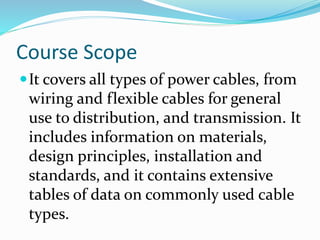
This document provides an overview of low voltage power cables. It discusses cable design principles including voltage ratings, conductor materials and sizes, insulation types, core identification, assembly processes, bedding, armoring, sheathing, and relevant standards. The key points are that low voltage cables operate between 300/500V and 600/1000V, use copper or aluminum conductors, and common insulation materials are PVC, XLPE, and EPR. Cores are typically identified by color and the document outlines the assembly, bedding, armoring, and sheathing processes. Finally, common international and national standards for low voltage cables are listed.
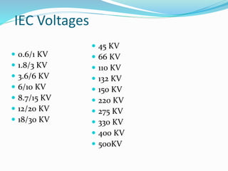
(PRIYA) Rajgurunagar Call Girls Just Call 7001035870 [ Cash on Delivery ] Pun...
Cable Basics Course Overview
1.
2. Course Scope
It covers all types of power cables, from
wiring and flexible cables for general
use to distribution, and transmission. It
includes information on materials,
design principles, installation and
standards, and it contains extensive
tables of data on commonly used cable
types.
7. Voltage :-
Any electric equipment is denoted by its operating
voltage , cables are denoted as U0/UKV where :_
Uo :- is the rated power frequency voltage between
conductor and earth or metallic screen for which cable
is designed.
U : is the rated power frequency voltage between
conductors for which the cable is designed
8. For example : Saying 0.6/1 (1.2) Kv cable means that
Uo (Phase voltage) = 0.6 Kv
U ( Line voltage) = 1 Kv
Cable is defined by its line voltage as when saying 15
kv cables we mean 8.7/15 Kv
18. 2) Comparison between O.H. conductors &U.G. cables:
O.H. CONDUCTOR U.G. CABLES
- Widely in transmission
Network & distribution net
work in urban areas
- Widely used in side towns where safety is requires
- Out door application - Both outdoor & Indoor (inside industrially residential &
Building, wiring & lighting application)
- Considered of less cost
compared with underground
cables
-Considered of higher cost compared with O.H conductors
Duration of an outage can be longer
since the failure tends to be more
difficult to locate and repair.
Duration of an outage is less .
Cable replacing due to load growth
is not easier. Therefore UGC should
be applied in areas where sharp load
growth would not be expected .
Conductor replacing is easier with some limits .
- Include processes of
1) Drawing section
2) Stranding section
- Includes processes of
1) Drawing section 6) Armoring section
2) Stranding section 7) Separation section
3) Insulation section 8) Lead section
4) Assembly section 9) Sheathing section
5) Bedding section
20. Voltage Grades of L.V. Cables:
300/500 V [Both sheath & non-sheath cable (insulated
wires)]
450/750 V [non-sheathed cables (insulated wires)]
600/1000 V or 0.6/1 kV (Sheathed cables)
21. Material of Conductors
1) Copper:
Soft annealed copper conductor
2) Aluminum:
Aluminum conductor (H12)
- Copper has excellent electrical and mechanical
properties but it is more expensive than
Aluminum as it is cheaper and lighter .
24. Types of Insulation
Poly Vinyl chloride ( PVC ) :
Thermo Plastic material
Maximum operating temp. is 70 °C
Maximum S.C. temp. 160 °C for C.S.A. 300mm2
Maximum S.C. temp. 140 °C for C.S.A. >300mm2
Cross linked polyethylene ( XLPE ):
Thermosetting material
Maximum operating temp. is 90 °C
Maximum S.C. temp. 250 °C
Ethylene propylene Rubber ( EPR ) :
Thermosetting material
Maximum operating temp. is 90 °C
Maximum S.C. temp. 250 °C
25. Cores Identification
Colors of cores are usually as following:
Single core : Natural, Red, etc…
2 cores : Red & Black
3 cores : Red, Yellow & Blue
4 cores : Red, Yellow, Blue & Black
5 cores : Red, Yellow, Blue, Black & Green
Grounding wire : Green & Green/Yellow
More than 5 : (Black + No. or White + No. ,etc…)
Cores identification can be as per customer
26. Assembly Process
The insulated cores assembly together with suitable lay
length (right hand).
Polypropylene filler (if necessary) to fill the space
between cores to make the assembled shape round .
Then wrapped with suitable tape to form a compact
round cable
27. Bedding Process
The main function of the Bedding is to give
mechanical protection for insulation in case of
armored cables only.
Material :
Extruded poly vinyl chloride ( PVC ) when there is
higher mechanical hazard we use polyethylene ( PE )
28. Armouring Process
The Armouring is used as mechanical
protection for direct burial cables.
It is used as an earthing conductor in some
Networks .
29. Material :
The steel is the suitable material for multi-core cables
Steel is applied in one of the following forms :
a) Tapes : Double tapes are applied helically
around the bedding of cables with 50 % gap.
b) Wires : Number of wires with the specified
diameter is to cover the bedding surface helically .
In case of single core cables steel is replaced with non magnetic
material like Aluminum to reduce the magnetic losses (eddy current) .
Armouring Process
30. Sheath Process
It is outer jacket of the cable , its main function is mechanical
protection.
Material :
Poly Vinyl Chloride (PVC) , When there is higher mechanical
hazard we can use Polyethylene (PE)
colour: Black or as per customer requirements
Special characteristics may be included such as:
Anti-Termite resistant
Oil resistant
Chemical resistant
Acids & Alkaline resistant … etc.
31. In case of mechanical hazard we can use
polyethylene materials such as
High Density Polyethylene [HDPE]
Medium Density Polyethylene [MDPE]
Linear Low Density Polyethylene [LLDPE]
32. STANDARDS
IEC :International Electro technical commission
BS : British standard institution
VDE : Verband Deutshcke Electroteche
NEMA : National Electrical Manufactures association
UL : Under writer Laboratory
ICEA : Insulated cable Engineers Association
HD : Harmonised Document
33. STANDARDS
IEC 60227 : Polyvinyl chloride insulated cables of rated voltage up to and
including 450/750 V
IEC 60228 : Conductors of insulated cables.
IEC 60502-1 : Cables for rated voltages of 1Kv (( Um =1.2 kV ) and
3 kV (Um =3.6kV)
BS 6004 : Electric cables - PVC insulated, non-armoured cables for
voltages up to and including 450/750 V, for electric power,
lighting and internal wiring
BS 7889 : Electric cables - Thermosetting insulated, un-armoured
cables for a voltage of 600/1000 V
BS 6346 : 600/1000 V and 1900/3300 V armoured electric cables having
PVC insulation.
BS 5467 : 600/1000 V and 1900/3300 V armoured electric cables having
thermosetting insulation.
34. SPECIFICATION
Standard
Type of conductor
Size of conductor
Number of cores
Description (CU/XLPE/SWA/PVC)
Customer special requirement
Editor's Notes
The drift of electrons within a conductor is known as an electric current,
measured in amperes and given the symbol I .
For a current to continue to flow, there must be a complete circuit for the
electrons to move around. If the circuit is broken by opening a switch, for
example, the electron flow and therefore the current will stop immediately.
To cause a current to flow continuously around a circuit, a driving force
is required, just as a circulating pump is required to drive water around a
central heating system. This driving force is the electromotive force (emf).
Each time an electron passes through the source of emf, more energy is
provided to send it on its way around the circuit.
An emf is always associated with energy conversion, such as chemical
to electrical in batteries and mechanical to electrical in generators. The
energy introduced into the circuit by the emf is transferred to the load terminals
by the circuit conductors.
The potential difference (p.d.) is the change in energy levels measured
across the load terminals. This is also called the volt drop or terminal voltage,
since emf and p.d. are both measured in volts. Resistance every circuit offers
some opposition to current fl ow, which we call the circuit resistance , measured
in ohms (symbol Ω ), to commemorate the famous German physicist
Georg Simon Ohm, who was responsible for the analysis of electrical circuits.
In 1826, Ohm published details of an experiment he had done to investigate
the relationship between the current passing through and the potential
difference between the ends of a wire. As a result of this experiment,
he arrived at a law, now known as Ohm’s law, which says that the current
passing through a conductor under constant temperature conditions is
proportional to the potential difference across the conductor.
The resistance or opposition to current fl ow varies for different materials,
each having a particular constant value. If we know the resistance of, say,
1 m of a material, then the resistance of 5 m will be fi ve times the resistance
of 1 m.