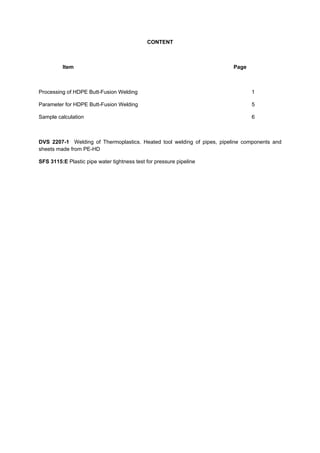
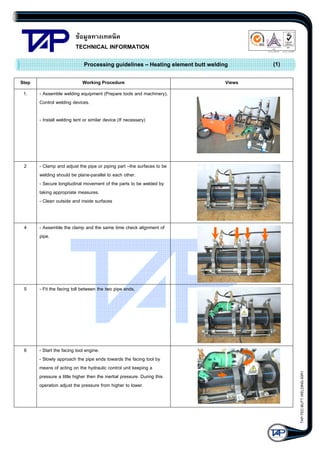
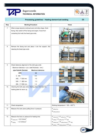
The document provides guidelines for HDPE butt-fusion welding, including:
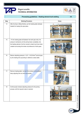
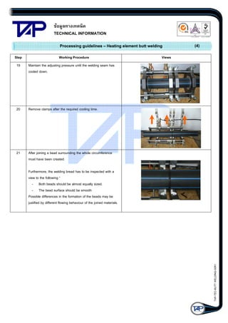
1) A 21-step process for HDPE butt-fusion welding with diagrams illustrating each step.
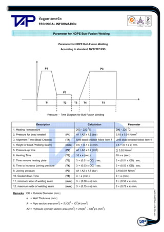
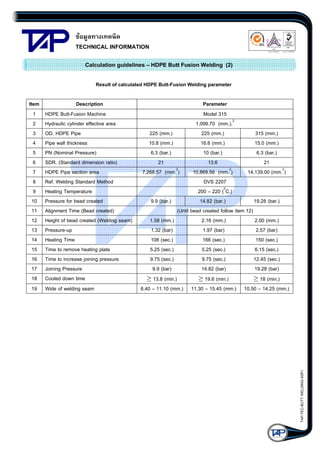
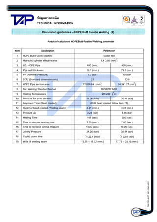
2) Parameters for HDPE butt-fusion welding including heating temperature, pressures and times for bead creation, heating, joining and cooling.
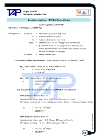
3) Sample calculations for determining welding pressures based on pipe and hydraulic cylinder dimensions and examples for different pipe sizes.