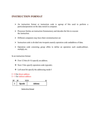
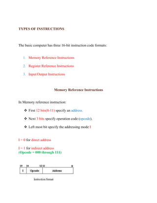
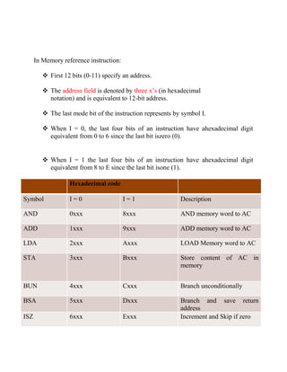
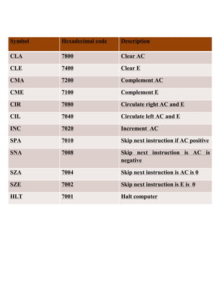
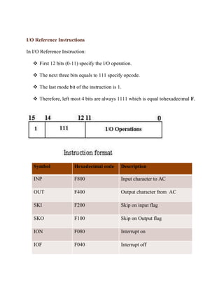
Punjab College of Technical
                 Education

REPORT

           INSTRUCTION FORMAT
INSTRUCTION FORMAT

    An instruction format or instruction code is agroup of bits used to perform a
     particularoperation on the data stored in computer.

    Processor fetches an instruction frommemory and decodes the bits to execute
     the instruction.

    Different computers may have their owninstruction set.

    Instruction code is divided into twoparts namely operation code andaddress of data.

    Operation code consisting group ofbits to define an operation such asadd,subtract,
     multiply etc.


In an instruction format:

    First 12 bits (0-11) specify an address.

    Next 3 bits specify operation code (opcode).

    Left most bit specify the addressing mode I

I = 0 for direct address
I = 1 for indirect address
TYPES OF INSTRUCTIONS


The basic computer has three 16-bit instruction code formats:


   1. Memory Reference Instructions

   2. Register Reference Instructions

   3. Input/Output Instructions


                           Memory Reference Instructions


In Memory reference instruction:

     First 12 bits(0-11) specify an address.

     Next 3 bits specify operation code (opcode).

     Left most bit specify the addressing mode I


I = 0 for direct address

I = 1 for indirect address
(Opcode = 000 through 111)
In Memory reference instruction:

          First 12 bits (0-11) specify an address.

          The address field is denoted by three x’s (in hexadecimal
           notation) and is equivalent to 12-bit address.

          The last mode bit of the instruction represents by symbol I.

          When I = 0, the last four bits of an instruction have ahexadecimal digit
           equivalent from 0 to 6 since the last bit iszero (0).


          When I = 1 the last four bits of an instruction have ahexadecimal digit
           equivalent from 8 to E since the last bit isone (1).

                   Hexadecimal code

Symbol             I=0                   I=1                 Description

AND                0xxx                  8xxx                AND memory word to AC

ADD                1xxx                  9xxx                ADD memory word to AC

LDA                2xxx                  Axxx                LOAD Memory word to AC

STA                3xxx                  Bxxx                Store content of AC in
                                                             memory


BUN                4xxx                  Cxxx                Branch unconditionally

BSA                5xxx                  Dxxx                Branch and save return
                                                             address
ISZ                6xxx                  Exxx                Increment and Skip if zero
Register Reference Instructions


In Register Reference Instruction:

    First 12 bits (0-11) specify the register operation.

    The next three bits equals to 111 specify opcode.

    The last mode bit of the instruction is 0.

    Therefore, left most 4 bits are always 0111 which is equal tohexadecimal 7.
Symbol   Hexadecimal code   Description

CLA      7800               Clear AC

CLE      7400               Clear E

CMA      7200               Complement AC

CME      7100               Complement E

CIR      7080               Circulate right AC and E

CIL      7040               Circulate left AC and E

INC      7020               Increment AC

SPA      7010               Skip next instruction if AC positive

SNA      7008               Skip next instruction is AC is
                            negative

SZA      7004               Skip next instruction is AC is 0

SZE      7002               Skip next instruction is E is 0

HLT      7001               Halt computer
I/O Reference Instructions

In I/O Reference Instruction:

    First 12 bits (0-11) specify the I/O operation.

    The next three bits equals to 111 specify opcode.

    The last mode bit of the instruction is 1.

    Therefore, left most 4 bits are always 1111 which is equal tohexadecimal F.


   Symbol              Hexadecimal code       Description

   INP                 F800                   Input character to AC

   OUT                 F400                   Output character from AC

   SKI                 F200                   Skip on input flag

   SKO                 F100                   Skip on Output flag

   ION                 F080                   Interrupt on

   IOF                 F040                   Interrupt off

Instructionformatreport 110419102141-phpapp02

  • 1.
    Punjab College ofTechnical Education REPORT INSTRUCTION FORMAT
  • 2.
    INSTRUCTION FORMAT  An instruction format or instruction code is agroup of bits used to perform a particularoperation on the data stored in computer.  Processor fetches an instruction frommemory and decodes the bits to execute the instruction.  Different computers may have their owninstruction set.  Instruction code is divided into twoparts namely operation code andaddress of data.  Operation code consisting group ofbits to define an operation such asadd,subtract, multiply etc. In an instruction format:  First 12 bits (0-11) specify an address.  Next 3 bits specify operation code (opcode).  Left most bit specify the addressing mode I I = 0 for direct address I = 1 for indirect address
  • 3.
    TYPES OF INSTRUCTIONS Thebasic computer has three 16-bit instruction code formats: 1. Memory Reference Instructions 2. Register Reference Instructions 3. Input/Output Instructions Memory Reference Instructions In Memory reference instruction:  First 12 bits(0-11) specify an address.  Next 3 bits specify operation code (opcode).  Left most bit specify the addressing mode I I = 0 for direct address I = 1 for indirect address (Opcode = 000 through 111)
  • 4.
    In Memory referenceinstruction:  First 12 bits (0-11) specify an address.  The address field is denoted by three x’s (in hexadecimal notation) and is equivalent to 12-bit address.  The last mode bit of the instruction represents by symbol I.  When I = 0, the last four bits of an instruction have ahexadecimal digit equivalent from 0 to 6 since the last bit iszero (0).  When I = 1 the last four bits of an instruction have ahexadecimal digit equivalent from 8 to E since the last bit isone (1). Hexadecimal code Symbol I=0 I=1 Description AND 0xxx 8xxx AND memory word to AC ADD 1xxx 9xxx ADD memory word to AC LDA 2xxx Axxx LOAD Memory word to AC STA 3xxx Bxxx Store content of AC in memory BUN 4xxx Cxxx Branch unconditionally BSA 5xxx Dxxx Branch and save return address ISZ 6xxx Exxx Increment and Skip if zero
  • 5.
    Register Reference Instructions InRegister Reference Instruction:  First 12 bits (0-11) specify the register operation.  The next three bits equals to 111 specify opcode.  The last mode bit of the instruction is 0.  Therefore, left most 4 bits are always 0111 which is equal tohexadecimal 7.
  • 6.
    Symbol Hexadecimal code Description CLA 7800 Clear AC CLE 7400 Clear E CMA 7200 Complement AC CME 7100 Complement E CIR 7080 Circulate right AC and E CIL 7040 Circulate left AC and E INC 7020 Increment AC SPA 7010 Skip next instruction if AC positive SNA 7008 Skip next instruction is AC is negative SZA 7004 Skip next instruction is AC is 0 SZE 7002 Skip next instruction is E is 0 HLT 7001 Halt computer
  • 7.
    I/O Reference Instructions InI/O Reference Instruction:  First 12 bits (0-11) specify the I/O operation.  The next three bits equals to 111 specify opcode.  The last mode bit of the instruction is 1.  Therefore, left most 4 bits are always 1111 which is equal tohexadecimal F. Symbol Hexadecimal code Description INP F800 Input character to AC OUT F400 Output character from AC SKI F200 Skip on input flag SKO F100 Skip on Output flag ION F080 Interrupt on IOF F040 Interrupt off