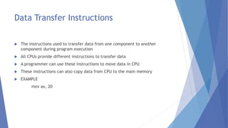
2nd Lecture
Instructions
 Instructions are sequence of bit that tells to processor or computer CPU to
perform a particular operations
 Instructions can also contain data to be used in the operation
Types of Instructions
 Data Movement/Transfer Instructions
 Arithmetic and logical instructions
 Program control instructions
 Input Output I/O Instructions
Data Transfer Instructions
 The instructions used to transfer data from one component to another
component during program execution
 All CPUs provide different instructions to transfer data
 A programmer can use these instructions to move data in CPU
 These instructions can also copy data from CPU to the main memory
 EXAMPLE
mov ax, 20
Arithmetic and logical instructions
 Addition subtraction multiplication and division are arithmetic operations
(+,-,*,/)
 Example:
Add ax,bx
Sub bx,ax
 Greater than, less than, equal to are logical operations (>,<,>=,<=,=,!=)
Program Control Instructions
 The instruction are used to change the sequence of instructions of a program
 These instructions transfer the execution control to a certain part of program
instead of next instruction
JUMP
JUMZ(jump if zero)
I/O Instructions
 Every CPU provides the operations of reading data from peripheral devices
and writing data to peripheral devices
Keyboard, mouse disk
Print “Hello World” on Screen
mov ah, 09h ; function to display message
mov dx, offset message ; offset of message string
int 21h ; DOS interrupt
mov ah, 4ch ; function terminate
int 21h ; DOS interrupt
ENDP
message db “Hello World$”
end main
3rd Lecture
Category of FLAG Register
 Status Flags
 Control Flags
Status Flag Registers
 There are 6 Status Flags in 8086 Processor
1) Carry Flag
2) Auxiliary Carry Flag
3) Parity Flag
4) Zero Flag
5) Overflow Flag
6) Sign Flag
Carry Flag Register
 If 9th bit generated, then the carry flag will be 1
 For example
1 0 0 1 0 0 0 1
1 0 0 1 0 0 0 1
1 0 0 1 0 0 0 1 0
Auxiliary Carry Flag Registers
 If the 4th bit contains carry, then AC is 1
 For Example
0 1 1 0 1 1 1 0
1 0 0 0 1 1 1 1
1 1 1 1 0 1 1 1
 4th bit generated carry so AC=1
Parity Flag Registers
 If number of ones in the bit are even, then parity flag is equal to one
 If number of ones in the bit are odd, then parity flag is equal to zero
 For example
0 1 1 0 1 1 1 0
0 0 0 0 1 1 1 1
0 1 1 1 0 1 1 1
0 1 1 0 1 1 1 0
1 0 0 0 1 1 1 1
1 1 1 1 0 1 1 1
The number of ones are even so PF=1 The number of ones are odd so PF=0
Zero Flag Registers
 If the answer is zero then ZF=1 otherwise ZF=0
Overflow Flag Registers
 If the bit are in the range -128 to 127 then OF=0 otherwise OF=1
 Example
 Bin=0110 1010, Hex = 6A
 𝟎 × 𝟐𝟕 + 𝟏 × 𝟐𝟔 + 𝟏 × 𝟐𝟓 + 𝟎 × 𝟐𝟒 + 𝟏 × 𝟐𝟑 + 𝟎 × 𝟐𝟐 + 𝟏 × 𝟐𝟏 + 𝟎 × 𝟐𝟎 = 𝟏𝟎𝟔
 Is in range so OF Register = 0
 Example
 Bin=1010 1010, Hex=AA
 𝟏 × 𝟐𝟕
+ 𝟎 × 𝟐𝟔
+ 𝟏 × 𝟐𝟓
+ 𝟎 × 𝟐𝟒
+ 𝟏 × 𝟐𝟑
+ 𝟎 × 𝟐𝟐
+ 𝟏 × 𝟐𝟏
+ 𝟎 × 𝟐𝟎
= 𝟏𝟕𝟎
 Is out of range so OF Register = 1
Sign Flag Register
 After any operation if the MSB(Most Significant Bit) is 1, then it indicates that
the number is negative
 And sign flag is set to 1
Lecture 4
Control Flag Registers
 There are 3 Control Flag in 8086 processors
1. Trap Flag
2. Interrupt Enable Flag
3. Direction Flag
Trap Flag (TF)
 It is used to set the trace mode i.e. start single stepping mode
 Here the microprocessor is interrupted after every instruction so that the
program can be debugged
Interrupt Enable Flag (IF)
 It is used to mask (disable) or unmask (enable) the INTR interrupt
 If users sets IF flag, the CPU will recognize external interrupt requests.
Clearing IF disables these interrupts
Direction Flag (DF)
 If this flag is set, SI and DI are in auto-decrementing mode in string operations
Addition, Subtraction, Multiplication,
Division
mov ax,7 ; ax = 7
add ax, 4 ; ax = ax+4
mov al,7 ; al = 7
mov bl,3 ; bl = 3
add al,bl ; bl = al+bl
Addition, Subtraction, Multiplication,
Division
mov al,7 ; al = 7
mov bl,3 ; bl = 3
sub al,bl ; bl = al-bl
mov ax,10 ; al = 10
mov bx,2 ; bl = 2
mul bx,ax ; mul = bl * al
Continue
Addition, Subtraction, Multiplication,
Division
mov al,10 ; al = 10
mov bl,2 ; bl = 2
div bl,al ; mul = bl / al
Continue
Basic Structure of Assembly Language
.mode small ; Define size of program
.stack 100h ; Define Storage of stack
.data ; Define Variable here
.code ; Write Assembly Program
Main Proc ; Write specific task/procedure here
.
.
.
Main End ; End procedure here
End Main ; End program here
Basic Structure of Assembly Language
.model small ; Model directive
Tiny  Data+Code Space:<=64kb
Small  Data+Code Space:Data<=64kb and code<=64kb
Medium  Data+Code Space:Data<=64kb and code<=Any size
Compact  Data+Code Space:Data<=Any size and Data<=64kb
Large  Data+Code Space:Data<=Any size and Data<=Any size
Huge  Data+Code Space:Data<=Any size and Data<=Any size
Continue
Data
Code
RAM
Write a program to print single character on
screen and multiple character on screen in
Assembly Language
.model small
.data
.code
main proc
mov dl, "A"
mov ah,2
int 21h
mov ah,4ch
int 21h
main endp
end main
Single Character Program
Write a program to print single character on
screen and multiple character on screen in
Assembly Language
.model small
.data
.code
main proc
mov dl, "M"
mov ah,2
int 21h
mov dl, "P"
mov ah,2
int 21h
mov dl, "G"
mov ah,2
int 21h
mov dl,"C"
mov ah,2
int 21h
mov ah,4ch
int 21h
main endp
end main
Multiple Character Program
Addressing Mode
 The way in which operands are specified
 Ways or model to access data is called addressing modes
 The term addressing modes refers to the way in which the operand of an
instruction is specified
 The operand may be mentioned directly or specified in register or memory
What is addressing mode?
 Addressing mode are different ways by which CPU can access data or operands
 They determine how to access a specific memory address
 To load any data from and to memory/register, MOV instruction is used
 The syntax of MOV instruction is:
 MOV destination, Source
Mov instruction addressing mode?
 The MOV instruction copies a byte or a word from source to destination
 Both operands should be of same type either byte or a word
 The syntax of MOV instruction is:
MOV destination, source
 Example
Mov ax,10
Types of addressing mode
 Register addressing mode
 Immediate addressing mode
 Direct addressing mode
 Register indirect addressing mode
 Based relative addressing mode
 Indexed relative addressing mode
 Based indexed addressing mode
Register addressing mode
 This mode involves the use of register
 These registers hold the operands
 This mode is very fast as compared to others because CPU doesn’t need to
access memory
 CPU can directly perform an operation through registers
 Example
 MOV AX,BX AX=BX
Immediate Addressing Mode
 In this mode, there are two operands
 One is a register and the other is a constant value
 The register comes quickly after the OP code
 Example
MOV AX, 405H AX=405H
MOV BX, 255 BX=255
Direct Addressing Mode
 Loads or stores the data from memory to register
 The instruction consists of a register and offset address
 Example
MOV AX, [ADDRESS]
Register Indirect Addressing Mode
 The register indirect addressing mode uses the offset address which resides in
one of these registers i.e. BX,SI,DI.
 The instruction consists of a register and offset address
 Example
MOV AX, [ADDRESS]
Based Relative Addressing Mode
 This addressing mode uses a base register either BX or BP and a displacement
value to calculate physical address
 Physical Address = Segment Register (Shifted to left by 1) + Effective address
 Example
MOV [AX+4], BX
Indexed Relative Addressing Mode
 This addressing mode is same as the based relative addressing mode
 The only difference is it uses DI and SI registers instead of BX and BP registers
 Example
MOV [DI]+12, BX
Based Indexed Addressing Mode
 The based indexed addressing mode is actually a combination of based
relative addressing mode and indexed relative addressing mode
 It uses one base register (BX,BP) and one index register (SI,DI)
 Example
MOV AX,[BX+SI+10]
How to take input and output in
assembly language
.mode small
.data
.code
main proc
Mov ah, 1 : 1 is used for output
Int 21h
Mov dl, al
Mov ah, 2 :2 is used for output
Int 21h
main endp

Assembly language.pptx

  • 1.
  • 2.
    Instructions  Instructions aresequence of bit that tells to processor or computer CPU to perform a particular operations  Instructions can also contain data to be used in the operation
  • 3.
    Types of Instructions Data Movement/Transfer Instructions  Arithmetic and logical instructions  Program control instructions  Input Output I/O Instructions
  • 4.
    Data Transfer Instructions The instructions used to transfer data from one component to another component during program execution  All CPUs provide different instructions to transfer data  A programmer can use these instructions to move data in CPU  These instructions can also copy data from CPU to the main memory  EXAMPLE mov ax, 20
  • 5.
    Arithmetic and logicalinstructions  Addition subtraction multiplication and division are arithmetic operations (+,-,*,/)  Example: Add ax,bx Sub bx,ax  Greater than, less than, equal to are logical operations (>,<,>=,<=,=,!=)
  • 6.
    Program Control Instructions The instruction are used to change the sequence of instructions of a program  These instructions transfer the execution control to a certain part of program instead of next instruction JUMP JUMZ(jump if zero)
  • 7.
    I/O Instructions  EveryCPU provides the operations of reading data from peripheral devices and writing data to peripheral devices Keyboard, mouse disk
  • 8.
    Print “Hello World”on Screen mov ah, 09h ; function to display message mov dx, offset message ; offset of message string int 21h ; DOS interrupt mov ah, 4ch ; function terminate int 21h ; DOS interrupt ENDP message db “Hello World$” end main
  • 9.
  • 10.
    Category of FLAGRegister  Status Flags  Control Flags
  • 11.
    Status Flag Registers There are 6 Status Flags in 8086 Processor 1) Carry Flag 2) Auxiliary Carry Flag 3) Parity Flag 4) Zero Flag 5) Overflow Flag 6) Sign Flag
  • 12.
    Carry Flag Register If 9th bit generated, then the carry flag will be 1  For example 1 0 0 1 0 0 0 1 1 0 0 1 0 0 0 1 1 0 0 1 0 0 0 1 0
  • 13.
    Auxiliary Carry FlagRegisters  If the 4th bit contains carry, then AC is 1  For Example 0 1 1 0 1 1 1 0 1 0 0 0 1 1 1 1 1 1 1 1 0 1 1 1  4th bit generated carry so AC=1
  • 14.
    Parity Flag Registers If number of ones in the bit are even, then parity flag is equal to one  If number of ones in the bit are odd, then parity flag is equal to zero  For example 0 1 1 0 1 1 1 0 0 0 0 0 1 1 1 1 0 1 1 1 0 1 1 1 0 1 1 0 1 1 1 0 1 0 0 0 1 1 1 1 1 1 1 1 0 1 1 1 The number of ones are even so PF=1 The number of ones are odd so PF=0
  • 15.
    Zero Flag Registers If the answer is zero then ZF=1 otherwise ZF=0
  • 16.
    Overflow Flag Registers If the bit are in the range -128 to 127 then OF=0 otherwise OF=1  Example  Bin=0110 1010, Hex = 6A  𝟎 × 𝟐𝟕 + 𝟏 × 𝟐𝟔 + 𝟏 × 𝟐𝟓 + 𝟎 × 𝟐𝟒 + 𝟏 × 𝟐𝟑 + 𝟎 × 𝟐𝟐 + 𝟏 × 𝟐𝟏 + 𝟎 × 𝟐𝟎 = 𝟏𝟎𝟔  Is in range so OF Register = 0  Example  Bin=1010 1010, Hex=AA  𝟏 × 𝟐𝟕 + 𝟎 × 𝟐𝟔 + 𝟏 × 𝟐𝟓 + 𝟎 × 𝟐𝟒 + 𝟏 × 𝟐𝟑 + 𝟎 × 𝟐𝟐 + 𝟏 × 𝟐𝟏 + 𝟎 × 𝟐𝟎 = 𝟏𝟕𝟎  Is out of range so OF Register = 1
  • 17.
    Sign Flag Register After any operation if the MSB(Most Significant Bit) is 1, then it indicates that the number is negative  And sign flag is set to 1
  • 18.
  • 19.
    Control Flag Registers There are 3 Control Flag in 8086 processors 1. Trap Flag 2. Interrupt Enable Flag 3. Direction Flag
  • 20.
    Trap Flag (TF) It is used to set the trace mode i.e. start single stepping mode  Here the microprocessor is interrupted after every instruction so that the program can be debugged
  • 21.
    Interrupt Enable Flag(IF)  It is used to mask (disable) or unmask (enable) the INTR interrupt  If users sets IF flag, the CPU will recognize external interrupt requests. Clearing IF disables these interrupts
  • 22.
    Direction Flag (DF) If this flag is set, SI and DI are in auto-decrementing mode in string operations
  • 23.
    Addition, Subtraction, Multiplication, Division movax,7 ; ax = 7 add ax, 4 ; ax = ax+4 mov al,7 ; al = 7 mov bl,3 ; bl = 3 add al,bl ; bl = al+bl
  • 24.
    Addition, Subtraction, Multiplication, Division moval,7 ; al = 7 mov bl,3 ; bl = 3 sub al,bl ; bl = al-bl mov ax,10 ; al = 10 mov bx,2 ; bl = 2 mul bx,ax ; mul = bl * al Continue
  • 25.
    Addition, Subtraction, Multiplication, Division moval,10 ; al = 10 mov bl,2 ; bl = 2 div bl,al ; mul = bl / al Continue
  • 26.
    Basic Structure ofAssembly Language .mode small ; Define size of program .stack 100h ; Define Storage of stack .data ; Define Variable here .code ; Write Assembly Program Main Proc ; Write specific task/procedure here . . . Main End ; End procedure here End Main ; End program here
  • 27.
    Basic Structure ofAssembly Language .model small ; Model directive Tiny  Data+Code Space:<=64kb Small  Data+Code Space:Data<=64kb and code<=64kb Medium  Data+Code Space:Data<=64kb and code<=Any size Compact  Data+Code Space:Data<=Any size and Data<=64kb Large  Data+Code Space:Data<=Any size and Data<=Any size Huge  Data+Code Space:Data<=Any size and Data<=Any size Continue Data Code RAM
  • 28.
    Write a programto print single character on screen and multiple character on screen in Assembly Language .model small .data .code main proc mov dl, "A" mov ah,2 int 21h mov ah,4ch int 21h main endp end main Single Character Program
  • 29.
    Write a programto print single character on screen and multiple character on screen in Assembly Language .model small .data .code main proc mov dl, "M" mov ah,2 int 21h mov dl, "P" mov ah,2 int 21h mov dl, "G" mov ah,2 int 21h mov dl,"C" mov ah,2 int 21h mov ah,4ch int 21h main endp end main Multiple Character Program
  • 30.
    Addressing Mode  Theway in which operands are specified  Ways or model to access data is called addressing modes  The term addressing modes refers to the way in which the operand of an instruction is specified  The operand may be mentioned directly or specified in register or memory
  • 31.
    What is addressingmode?  Addressing mode are different ways by which CPU can access data or operands  They determine how to access a specific memory address  To load any data from and to memory/register, MOV instruction is used  The syntax of MOV instruction is:  MOV destination, Source
  • 32.
    Mov instruction addressingmode?  The MOV instruction copies a byte or a word from source to destination  Both operands should be of same type either byte or a word  The syntax of MOV instruction is: MOV destination, source  Example Mov ax,10
  • 33.
    Types of addressingmode  Register addressing mode  Immediate addressing mode  Direct addressing mode  Register indirect addressing mode  Based relative addressing mode  Indexed relative addressing mode  Based indexed addressing mode
  • 34.
    Register addressing mode This mode involves the use of register  These registers hold the operands  This mode is very fast as compared to others because CPU doesn’t need to access memory  CPU can directly perform an operation through registers  Example  MOV AX,BX AX=BX
  • 35.
    Immediate Addressing Mode In this mode, there are two operands  One is a register and the other is a constant value  The register comes quickly after the OP code  Example MOV AX, 405H AX=405H MOV BX, 255 BX=255
  • 36.
    Direct Addressing Mode Loads or stores the data from memory to register  The instruction consists of a register and offset address  Example MOV AX, [ADDRESS]
  • 37.
    Register Indirect AddressingMode  The register indirect addressing mode uses the offset address which resides in one of these registers i.e. BX,SI,DI.  The instruction consists of a register and offset address  Example MOV AX, [ADDRESS]
  • 38.
    Based Relative AddressingMode  This addressing mode uses a base register either BX or BP and a displacement value to calculate physical address  Physical Address = Segment Register (Shifted to left by 1) + Effective address  Example MOV [AX+4], BX
  • 39.
    Indexed Relative AddressingMode  This addressing mode is same as the based relative addressing mode  The only difference is it uses DI and SI registers instead of BX and BP registers  Example MOV [DI]+12, BX
  • 40.
    Based Indexed AddressingMode  The based indexed addressing mode is actually a combination of based relative addressing mode and indexed relative addressing mode  It uses one base register (BX,BP) and one index register (SI,DI)  Example MOV AX,[BX+SI+10]
  • 41.
    How to takeinput and output in assembly language .mode small .data .code main proc Mov ah, 1 : 1 is used for output Int 21h Mov dl, al Mov ah, 2 :2 is used for output Int 21h main endp