Download to read offline

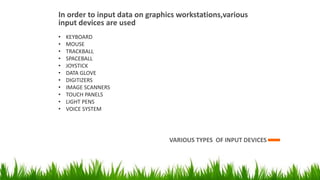
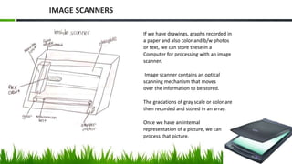
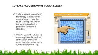

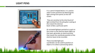


The document discusses various input devices used for graphics workstations, including keyboards, mice, trackballs, spaceballs, joysticks, data gloves, digitizers, image scanners, touch panels, light pens, and voice systems. Image scanners work by placing an image on a glass plate and using a scanning unit with light sensors to convert the image to digital pixel data. Touch panels detect screen positions touched by the user using either optical, electrical, or acoustic methods. Light pens allow screen positions to be selected by detecting the light emitted from a CRT screen. Voice systems use speech recognition to accept voice commands by matching input to a predefined dictionary.