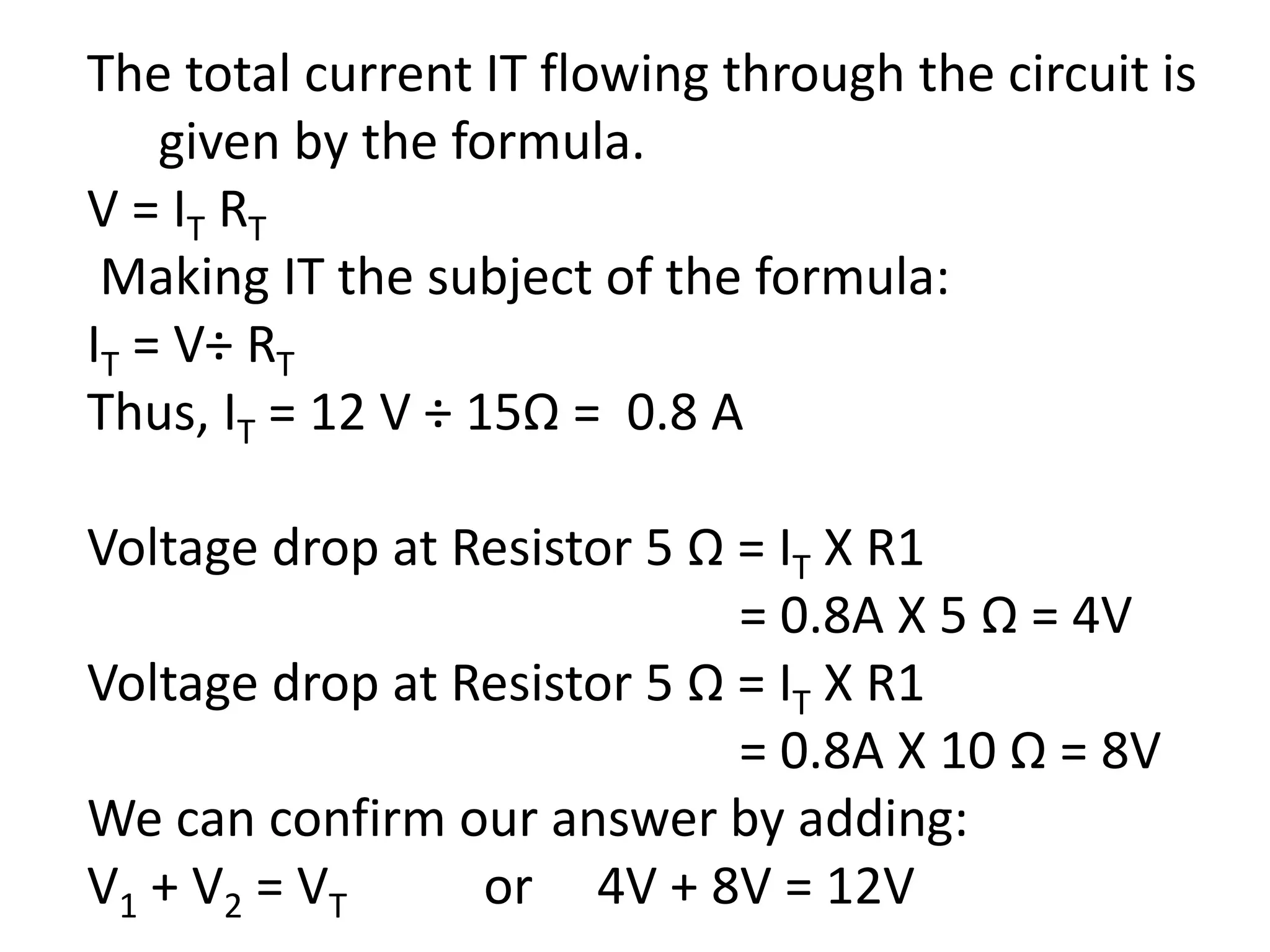
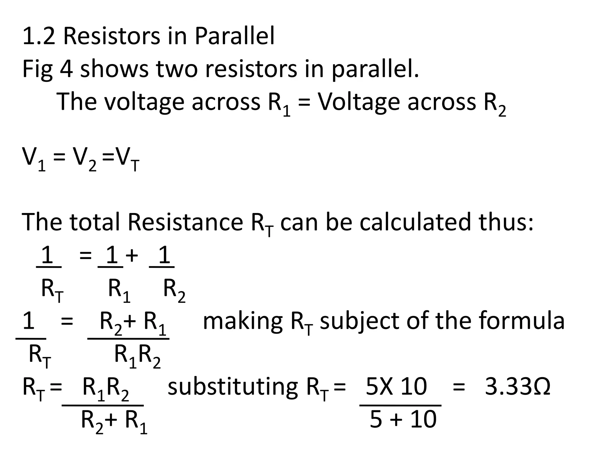
FET College Registrations
& Matric Rewrite
Matric Rewrite: Old, New & Technical
Matric
Mechanical Engineering N1 – N6
Electrical Engineering N1 – N6
Civil Engineering N1 – N6
Business Qualifications N4 – N6
Phone: 073 090 2954
Fax: 011 604 2771
Email:
Electrical Engineering
Industrial Electronics N2
Resistors in Parallel
Resistors in Series
Combination of Resistors in Parallel
and Resistors in Series
1.1The figure below shows two resistors in series.
Fig 1
Resistors in series are added up.
RT = (5 + 10) Ohms = 15 Ohms
The equivalent circuit based on the total
resistance of 15 Ohms becomes:
Fig 2
R1 = 5Ω R2 = 10Ω
12 V
RT = 15Ω
12 V
IT
IT
The total current IT flowing through the circuit is
given by the formula.
V = IT RT
Making IT the subject of the formula:
IT = V÷ RT
Thus, IT = 12 V ÷ 15Ω = 0.8 A
Voltage drop at Resistor 5 Ω = IT X R1
= 0.8A X 5 Ω = 4V
Voltage drop at Resistor 5 Ω = IT X R1
= 0.8A X 10 Ω = 8V
We can confirm our answer by adding:
V1 + V2 = VT or 4V + 8V = 12V
R1 = 5Ω R2 = 10Ω
12 V
IT
V1 V2
R1 = 5Ω
R2 = 10Ω
12 V
I1
I2
IT
Fig 2
Fig 3 The sum of voltage drops across resistors
Fig 4 Resistors in Parallel
A
1.2 Resistors in Parallel
Fig 4 shows two resistors in parallel.
The voltage across R1 = Voltage across R2
V1 = V2 =VT
The total Resistance RT can be calculated thus:
1 = 1 + 1
RT R1 R2
1 = R2+ R1 making RT subject of the formula
RT R1R2
RT = R1R2 substituting RT = 5X 10 = 3.33Ω
R2+ R1 5 + 10
Similarly, IT = V/RT = 12V/3.33 Ω = 3.604 A
Applying Kirchhoff's Current law to node A
IT = I1 + I2
This means that I1 and I2 ,have been divided in a
certain ratio such that:
VT = I1 X R1 and VT = I2 X R2
Thus : I1 = VT and I2 = VT
R1 R2
Substituting these values into Equation IT = I1 + I2
IT = VT + VT = 12V + 12V = 2.4 A + 1.2 A = 3.6A
R1 R2 5 10
R3 = 10Ω
VT = 12 V
I2
I3
IT
1.3 Combination of Resistors in Series and
Resistors in Parallel.
Based on the formula: VT = V1 + V2
V2 = VT – V1 where V1 = IT X R1
In order to calculate IT, it is necessary to find the
value of the total resistance RT since IT = VT ÷
RT
RT = R1 + RP = (6 + 3.33) Ω = 9.33 Ω
I1
R2 = 5Ω
R1 = 6Ω
V1 V2
A
Where RP = Total Resistance in the parallel
branch.
IT = 12V/9.33 Ω = 1.286 A
Thus V1 = 1.286 A X 6 Ω = 7.717 V
Now going back to our formula for V2:
V2 = VT – V1 = (12 - 7.717 )V = 4.283 V
Calculating I2 and I3:
The voltage across each of the branches are the
same . V2 = I2 X R2 = I3 X R3
I2 = 4.283V ÷ 5 Ω = 0.857 A and
I3 = 4.283V ÷ 10 Ω = 0.428 A.
We can confirm our answer by adding up the
current at node A:
IT = I2 + I3
0.857 A + 0.428 A = 1.2853 A

Industrial electronics n2

  • 2.
    FET College Registrations &Matric Rewrite Matric Rewrite: Old, New & Technical Matric Mechanical Engineering N1 – N6 Electrical Engineering N1 – N6 Civil Engineering N1 – N6 Business Qualifications N4 – N6 Phone: 073 090 2954 Fax: 011 604 2771 Email:
  • 3.
    Electrical Engineering Industrial ElectronicsN2 Resistors in Parallel Resistors in Series Combination of Resistors in Parallel and Resistors in Series
  • 4.
    1.1The figure belowshows two resistors in series. Fig 1 Resistors in series are added up. RT = (5 + 10) Ohms = 15 Ohms The equivalent circuit based on the total resistance of 15 Ohms becomes: Fig 2 R1 = 5Ω R2 = 10Ω 12 V RT = 15Ω 12 V IT IT
  • 5.
    The total currentIT flowing through the circuit is given by the formula. V = IT RT Making IT the subject of the formula: IT = V÷ RT Thus, IT = 12 V ÷ 15Ω = 0.8 A Voltage drop at Resistor 5 Ω = IT X R1 = 0.8A X 5 Ω = 4V Voltage drop at Resistor 5 Ω = IT X R1 = 0.8A X 10 Ω = 8V We can confirm our answer by adding: V1 + V2 = VT or 4V + 8V = 12V
  • 6.
    R1 = 5ΩR2 = 10Ω 12 V IT V1 V2 R1 = 5Ω R2 = 10Ω 12 V I1 I2 IT Fig 2 Fig 3 The sum of voltage drops across resistors Fig 4 Resistors in Parallel A
  • 7.
    1.2 Resistors inParallel Fig 4 shows two resistors in parallel. The voltage across R1 = Voltage across R2 V1 = V2 =VT The total Resistance RT can be calculated thus: 1 = 1 + 1 RT R1 R2 1 = R2+ R1 making RT subject of the formula RT R1R2 RT = R1R2 substituting RT = 5X 10 = 3.33Ω R2+ R1 5 + 10
  • 8.
    Similarly, IT =V/RT = 12V/3.33 Ω = 3.604 A Applying Kirchhoff's Current law to node A IT = I1 + I2 This means that I1 and I2 ,have been divided in a certain ratio such that: VT = I1 X R1 and VT = I2 X R2 Thus : I1 = VT and I2 = VT R1 R2 Substituting these values into Equation IT = I1 + I2 IT = VT + VT = 12V + 12V = 2.4 A + 1.2 A = 3.6A R1 R2 5 10
  • 9.
    R3 = 10Ω VT= 12 V I2 I3 IT 1.3 Combination of Resistors in Series and Resistors in Parallel. Based on the formula: VT = V1 + V2 V2 = VT – V1 where V1 = IT X R1 In order to calculate IT, it is necessary to find the value of the total resistance RT since IT = VT ÷ RT RT = R1 + RP = (6 + 3.33) Ω = 9.33 Ω I1 R2 = 5Ω R1 = 6Ω V1 V2 A
  • 10.
    Where RP =Total Resistance in the parallel branch. IT = 12V/9.33 Ω = 1.286 A Thus V1 = 1.286 A X 6 Ω = 7.717 V Now going back to our formula for V2: V2 = VT – V1 = (12 - 7.717 )V = 4.283 V Calculating I2 and I3: The voltage across each of the branches are the same . V2 = I2 X R2 = I3 X R3 I2 = 4.283V ÷ 5 Ω = 0.857 A and I3 = 4.283V ÷ 10 Ω = 0.428 A.
  • 11.
    We can confirmour answer by adding up the current at node A: IT = I2 + I3 0.857 A + 0.428 A = 1.2853 A