INTENDED
LEARNING
OUTCOMES:
After completing this
unit,you are
expected to:
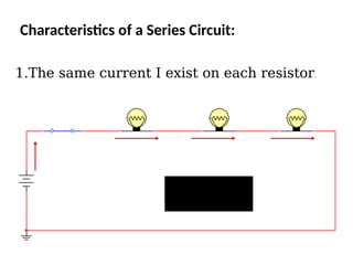
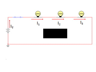
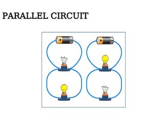
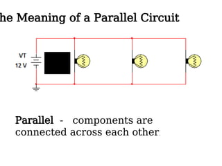
1. identify a series circuit and parallel.
2. apply Ohm’s law to find the current, voltages, and
resistances in a series circuit and parallel circuit.
3. apply Kirchhoff’s voltage law.
4. devise and use voltage dividers and current.
5. determine the total power in a series circuit and
parallel.
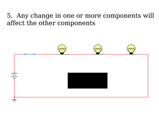
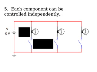
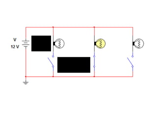
5. Any changein one or more components will
affect the other components.
15.
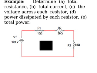
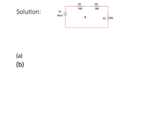
Example: Determine (a)total
resistance, (b) total current, (c) the
voltage across each resistor, (d)
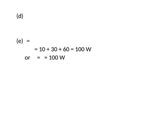
power dissipated by each resistor, (e)
total power.
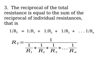
3. The reciprocalof the total
resistance is equal to the sum of the
reciprocal of individual resistances,
that is,
1/RT
= 1/R1
+ 1/R2
+ 1/R3
+ . . . 1/Rn
𝑅𝑇 =
1
1
𝑅1
+
1
𝑅2
+
1
𝑅3
+ .. .
1
𝑅𝑛
30.
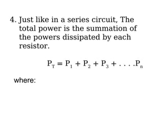
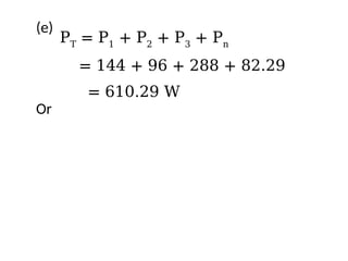
4. Just likein a series circuit, The
total power is the summation of
the powers dissipated by each
resistor.
PT
= P1
+ P2
+ P3
+ . . . .Pn
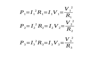
where:
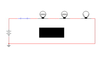
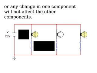
or any changein one component
will not affect the other
components.
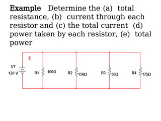
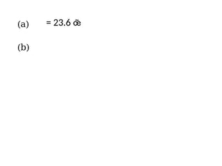
35.
Example Determine the(a) total
resistance, (b) current through each
resistor and (c) the total current (d)
power taken by each resistor, (e) total
power
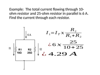
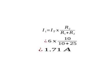
Example: The totalcurrent flowing through 10-
ohm resistor and 25-ohm resistor in parallel is 6 A.
Find the current through each resistor.
R1
10Ω
R2
25Ω
I1 I2
6A
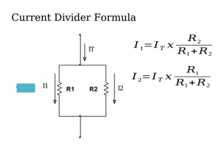
𝐼1=𝐼𝑇 𝑥
𝑅2
𝑅1 +𝑅2
¿ 6 𝑥
25
10+ 25
¿ 4.29 𝐴
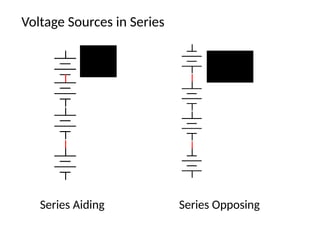
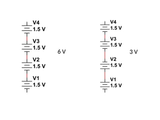
Voltage Sources inParallel
Ideal voltage sources are connected in
parallel in order to supply a higher and at
the same time a high power to a load.
In industry paralleling of voltage sources
such as generators are done in order to
sustain an increasing amount of load.
Conditions of Parallel Connection of Voltage
Sources:
1.They must have the same terminal voltage.
2.They must be connected in the same
polarity.