Download to read offline


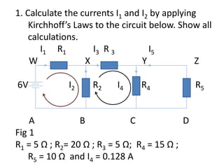
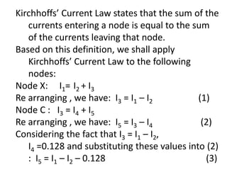
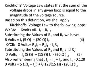
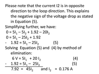
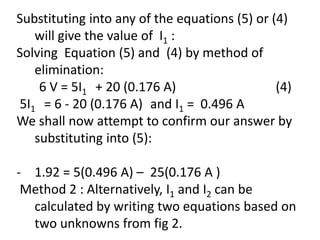
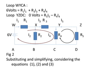
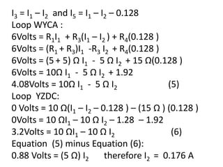
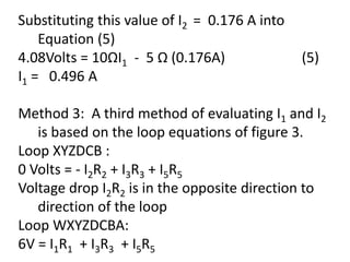
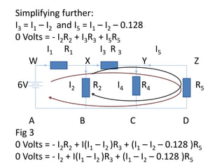
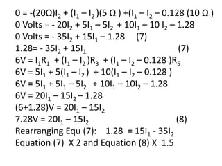


This document discusses calculating currents in an electrical circuit using Kirchhoff's laws. It provides the circuit diagram and component values. It then shows calculations using Kirchhoff's current law and voltage law to find the unknown currents I1 and I2. Three different methods are presented that calculate I1 = 0.496 A and I2 = 0.176 A by setting up loop equations and solving simultaneously.