1. INTRODUCTION
Electricity is an essential part of the modern life experience, and as an engineer it is essential to know how it
behaves and responds to changes in its trajectory. One of the most important laws in electrical circuits is the
ohms law which gives the relationship between current, resistance and voltage. This lab was divided into two
parts namely Part 1 is about measuring the currents of the different branches of a circuit connected to only one
power supply, and the voltages across each resistor and each node these were performed twice on figures 3(A)
and 3(B) and 0n figure(4) below. Part 2 is about determining how a circuit with two power supplies behave in
terms of node voltages, current divisions and voltage divisions between the branches figure (5) was used in
this analysis. The objective of this laboratory is to familiarize students with ohms law in practical situations
and not just theoretically, so that they can see its importance in the electrical world.
Therefore this report shall take the following format (theory, pre lab questions, equipment used, procedures,
results, discussions conclusions.
THEORY
Ohms law states that the resistance across component within a circuit is directly proportional to
that components voltage but inversely proportional to its current.
Resistance=voltage/current (Equation 1)
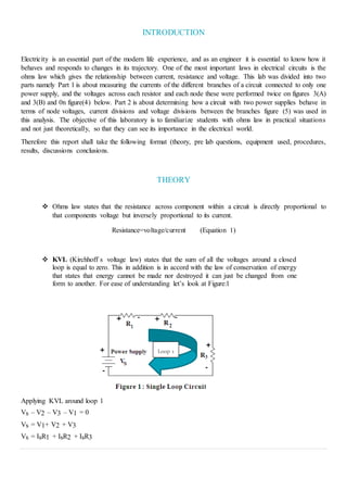
KVL (Kirchhoff`s voltage law) states that the sum of all the voltages around a closed
loop is equal to zero. This in addition is in accord with the law of conservation of energy
that states that energy cannot be made nor destroyed it can just be changed from one
form to another. For ease of understanding let’s look at Figure:1
Applying KVL around loop 1
Vs – V2 – V3 – V1 = 0
Vs = V1+ V2 + V3
Vs = IsR1 + IsR2 + IsR3
Loop 1
2. Vs = (R1 + R2 + R3) Is
The equivalent resistance for resistors in series may be replaced with a single resistance. This is a
direct extension of the Kirchhoff’s law therefore Req = R1 + R2 + R3 only for resistors in series.
A node of a network is defined as a point where two or more branches are joined. If three or more
branches join at a node, then that node is called a principal node or junction.
KCL (Kirchhoff’s current law) states that the sum of all currents entering a node is equal to the sum
of all currents leaving the node. This however also verifies the law of conservation of energy at a
node, this law is stated above on the second bullet. For simplicity let us consider the single node
circuit illustrated in Figure:2.
IS - I1 - I2 - I3 = 0
IS = I1 + I2 + I3
Equivalent resistance for resistors in parallel is denoted by the following equation REQ = 1 / (1 / R1
+ 1 / R2 + 1 / R3).
PRE-LAB
For the pre- lab that follows these below are the figures used.
Figures 3a and 3b were used in question 1 and 2
3. Figure 4 was used in question 3
Figure 5 was used in questions 4 and 5 respectively.
4. EQUIPMENT USED
1. POWER SUPPLY
2. Digital Multimeters (DMM) will serve as both the voltmeter and the ammeter)
3. Discrete Resistors and/or Decade Resistor Box(s)
PROCEEDURES
PART: 1 OF THE REPORT
Point 1
Set up each of the resistor arrangements as illustrated in Figures 3a and 3b above using discrete resistors.
Use the list provided to determine the resistances of the different discrete resistors.
For each arrangement use an ohmmeter to measure the resistance between points A –B and record your
results in Table 1.
Point 2
Again use Figures 3a and 3b. Apply a nominal 10.0V source across terminals A and B with ground at
terminal B. (Remember to limit the current to100-mA)
Measure the current entering terminal A, currents in each branch and the voltage across each resistor.
Record your values in Table 2.
Point 3
Build the circuit illustrated in Figure 4 above.
Limit the current supply to 100-mA and adjust the voltage supply to 10.0 V. Measure the following: VR1,
VR2, VR3, VR4, VW, VX, and VY.
Record your values in Table 3.
Note the polarities of all the voltages.
Measure the following currents: I1, I2, I3, and I4 record them in the same Table 3 with voltages and note
their polarities.
5. PART: 2 OF THE REPORT
Build the circuit illustrated in Figure 5 above.
Limit the current supply to 200-mA.
Adjust the voltage supplies to 10.0 V and 15.0 V.
Measure the following: VR1, VR2, VR3, VW, VX, and VY.
Record your values in Table 3. Note the polarities of all the voltages.
Measure the following currents: I1, I2 and I3 record them in the same Table 3 with voltages and note their
polarities.
RESULTS
PART 1 OF THE LAB
1.
RESISTANCE ACROSS TERMINALS A-B (K
FIGURE 3A 2.41
FIGURE 3B 5.24
TABLE 1
2.
FIGURE
3A
CURRENT ACROSS
TERMINALS AB (MA)
BRANCH/RESISTOR
NUMBER
CURRENT ACROSS
TERMINAL M(A)
VOLTAGE IN
RESISTOR (V)
4
1 4 3.58
2 2 6.35
3 2.1 9.9
FIGURE
3B
1.9
1 1.9 8.64
2 0.9 1.43
3 0.9 1.43
TABLE 2
6. 3.
RESISTOR NUMBER
VOLTAGE(V)
CURRENT
(MA)
VOLTAGES ABOUT
POINTS VOLTAGE (V)
1 2.7 1.8 v(rw) 10
2 2.1 2.1 v(rx) 7.2
3 0.6 2.1 v(ry) 2.7
4 1.2 4
TABLE 3
PART 2 OF THE LAB
4.
RESISTOR
NUMBERS VOLTAGE (V)
CURRENTS
(MA) NODES VOLTAGES ABOUT NODES (V)
1 0.804 0.438 VW 10
2 9.25 6 VX 4.96
3 5.77 5.6 VY 15
TABLE 4
DISCUSSIONS
PART 1 OF THE LAB
According to table 1 the conclusion that resistance within a circuit decreases if the resistors are connected in
parallel. Furthermore according to ohms law we could determine that the current 1 in table 2 can be proved with
KCL due to the fact that current 2 plus current 3 is equal to current 1 following the laws of the conservation of
energy. It is also obvious in table 2 that voltage in parallel circuits is the same as in 3b and in series it is differe nt
as experienced in table 2 part 3a. These voltages have one thing in common, this is that they add up to the source
voltage.
As we move on to table 3 from figure 4 it is apparent that this circuit follows ohms law in the sense that the current
about the resistor 1 is the current from the source and by current division the next 2 currents are found. The law
of conservation of energy is further emphasized when the summation of the voltages in every branch adds up to
the source voltage proving that energy was changed from one form to another and not destroyed. Any changes
are due to internal resistance of the conductors. These currents can be proved theoretically by making the use of
(the information provided from bullets 1 through 7) from the theory part of this report.
7. PART 2 OF THE LAB
The voltage between the sources is the difference between the two sources at node (vx) in this case 15v – 10v=
5 volts according to ohms theoretical law but experimentally this is 4.96v. The voltage around loop 1 adds up to
the source voltage which is 10 volts this in node (vw). While the same thing happens at node (vy) with the result
as 15V. This same results can be obtained by making the use of KVL together with KCL and using the
superposition principle.
CONCLUSION
In conclusion with all of the above information and all of the theoretical similarities in the results obtained
experimentally it is safe to assume that ohms law explains how any circuit operates in terms of voltage, current
and resistance. In addition the only thing that changes the results is the problem of internal resistance, this
change is so small that it can be considered negligible. Furthermore this knowledge will aid me in my
engineering career both theoretically and practically.
8. REFERENCES
Bird, J. (2003). electrical circuit theory and thechnology. boston: Newnes.