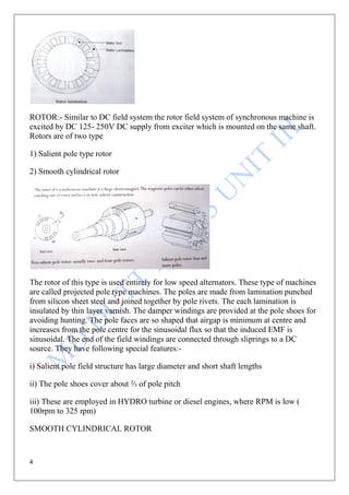
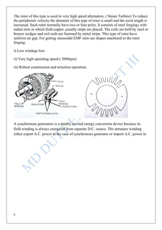
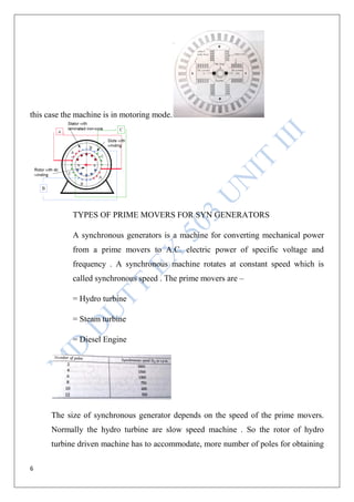
SlideShare a Scribd company logo
1
READING MATERIAL FOR B.E. STUDENTS
OF RGPV AFFILIATED ENGINEERING COLLEGES
BRANCH V SEM ELECTRICAL AND ELECTRONICS
SUBJECT ELECTRICAL MACHINES II
Professor MD Dutt
Addl General Manager (Retd)
BHARAT HEAVY ELECTRICALS LIMITED
Professor(Ex) in EX Department
Bansal Institute of Science and Technology
Kokta Anand Nagar BHOPAL
Presently Head of The Department ( EX)
Shri Ram College Of Technology
Thuakheda BHOPAL
Sub Code EX 503 Subject Electrical Machines II
UNIT III Synchronous Machine I
2
EX 503
UNIT III Synchronous Machine I
RG PV Syllabus
Construction, types of prime movers, excitation system including brushless
excitation. Polyphase distributive winding, integral slot winding and
fractional windings, emf equation, generation of harmonics and their
elimination. Armature reaction, synchronous reactance and impedance.
Equivalent circuit of alternator, relation between generated voltage and
terminal voltage. Voltage regulation of alternators using synchronous
impedance,mmf,zpf and new ASA method.
INDEX
S No Topic Page
1 Construction , types of prime mover 3,4,5,6,7
2 Excitation system including brushless excitation 7,8,9
3 Polyphase distributive winding, integral slot winding and
fractional windings, emf equation
9,10,11,12
4 Generation of harmonics and their elimination 12,13,
5 Armature reaction, synchronous reactance & impedance 13,14,15
6 Equivalent circuit of alternator 15,16
7 Relation between generated voltage and terminal voltage 16,17,18
8 Voltage regulation of alternators using synchronous impedance 18,19,20,21
9 MMF,ZPF and new ASA method. 21,22,23,24
3
CONSTRUCTION FEATURES AND TYPE OF PRIME MOVERS.
In the electrical machines-1 in 4th
semester we have gone through the following topics
(1) Transformer,
(2) And three phase induction motor.
The induction motor is a asynchronous machine. The synchronous machine is the
machine which operates at synchronous speed. To work out synchronous speed the
following formula is used.
N =
N = speed
F = frequency
P = poles
First of all we will revise what we had learnt in 4th
semester for induction motor, As the
induction motor is a rotating machine the synchronous generators are also rotating
machine having mainly following feather`s.
Construction features:-
As induction motor the synchronous generators have three main component.
(1) An Armature winding in the stator
(2) A magnetic circuit, called exciting or field winding for the production of flux.
(3) An arrangement to cut the magnetic flux by armature winding.
CONSTRUCTION OF SYNCHRONOUS MOTOR:- The synchronous motor
essentially consists of two parts mainly the armature ( stator) and field magnet system (
rotor).
STATOR : - The armature is an iron ring formed of laminations of special magnetic
material ( silicon sheet steel) . It is having slots on the inner periphery to accommodate
armature conductors and is known as stator. The whole structure is held in a cast iron or
fabricated frame. The field rotates in between the stator, flux of rotating field cuts the
stator core continuously and causes eddy current losses in the core. The laminations are
insulated from each other by thin layer of varnish.
4
ROTOR:- Similar to DC field system the rotor field system of synchronous machine is
excited by DC 125- 250V DC supply from exciter which is mounted on the same shaft.
Rotors are of two type
1) Salient pole type rotor
2) Smooth cylindrical rotor
The rotor of this type is used entirely for low speed alternators. These type of machines
are called projected pole type machines. The poles are made from lamination punched
from silicon sheet steel and joined together by pole rivets. The each lamination is
insulated by thin layer varnish. The damper windings are provided at the pole shoes for
avoiding hunting. The pole faces are so shaped that airgap is minimum at centre and
increases from the pole centre for the sinusoidal flux so that the induced EMF is
sinusoidal. The end of the field windings are connected through sliprings to a DC
source. They have following special features:-
i) Salient pole field structure has large diameter and short shaft lengths
ii) The pole shoes cover about ⅔ of pole pitch
iii) These are employed in HYDRO turbine or diesel engines, where RPM is low (
100rpm to 325 rpm)
SMOOTH CYLINDRICAL ROTOR
5
The rotor of this type is used in very high speed alternators. ( Steam Turbine) To reduce
the peripherals velocity the diameter of this type of rotor is small and the axial length is
increased. Such rotor normally have two or four poles. It consists of steel forgings with
radial slots in which field copper ,usually strips are placed. The coils are held by steel or
bronze wedges and coil ends are fastened by metal strips. This type of rotor have
uniform air gap. For getting sinusoidal EMF slots are shapes machined in the rotor
forging.
i) Less windage loss
ii) Very high operating speed ( 3000rpm)
iii) Robust construction and noiseless operation.
A synchronous generators is a doubly excited energy conversion device because its
field winding is always energized from separate D.C. source. The armature winding
either export A.C. power in the case of synchronous generator or import A.C. power in
6
this case the machine is in motoring mode.
TYPES OF PRIME MOVERS FOR SYN GENERATORS
A synchronous generators is a machine for converting mechanical power
from a prime movers to A.C. electric power of specific voltage and
frequency . A synchronous machine rotates at constant speed which is
called synchronous speed . The prime movers are –
= Hydro turbine
= Steam turbine
= Diesel Engine
The size of synchronous generator depends on the speed of the prime movers.
Normally the hydro turbine are slow speed machine . So the rotor of hydro
turbine driven machine has to accommodate, more number of poles for obtaining
7
synchronous speed. So salient pole generator are driven by hydro turbine . The
diameter D is large compare to core length.
Where the speed of prime movers is high the cylindrical rotor construction is
used and the size of generator depends on the mechanical strength of the material
of shaft. The centrifugal forces in case steam turbine driven generator is very
high. Due to this the diameter of cylindrical rotor machine are less compare to the
core length.
In addition to the criteria of speed, The synchronous machine are large in size
and lots of heat is generated due to the losses in the machine. The size of
generator depends upon the type of cooling used to take away the heat generated.
= Closed circuit water cooled CACW
= Closed circuit air cooled CACA
= Closed circuit hydrogen cooled
= Closed circuit with water flow through the conductor
So the two major points which are the main consideration for the size of
synchronous generator is speed and cooling
EXCITATION SYSTEM FOR SYNCHRONOUS MACHINES
In large synchronous machines, the field winding is always provided on rotor, the
D.C. excitation to field winding is provided by fallowing three methods.
1) D.C. Excitation
2) Static Excitation
3) Brushless Excitation
1) D.C. Excitation – In D.C. excitation system three machines are used, one is
called pilot exciter, another is called main exciter and main 3 phase alternators
are mechanically coupled and they are mounted and driven by the single shaft
. The pilot exciter is D.C. shunt generator feeding the DC supply to field
8
winding of main exciter. The armature output of main field exciter is fitted
through brushes and slip rings to the main field of the alternators, as shown in
figure. This type of excitation requires maintenance of slip rings and
commutator of both the pilot exciter and main exciter armature to alternatively
static excitation or brushless excitation system are more popularly used now a
days for large rating machines.
2.STATIC Excitation – In this method of excitation of power through regulator
and current transformer and potential transformer are drown from main and fed
to thyristor bridge after stepping down the voltage by transformer TR, The D.C.
output of the thyristor bridge is fed through the brushes and slip ring to the field
winding of main alternators .Initially the D.C. excitation is provided to main field
winding from 125v battery bank to establish the field current in the exciter . After
building of the A.C. voltage sufficiently, the alternator is disconnected from
battery and switched on to the thyristor bridge output. The advantages of static
excitations are –
i)The excitation system is simple in design and provide fast response
characteristics as required in modern power system .
ii)Since there is no commutator of pilot and main exciter the friction, windage
and commutator losses are nil in this case , The maintenance cost is reduced .
iii) Since excitation is taken directly from the alternator terminal voltage ,
the system performance improves considerably .
9
3)BRUSHLESS Excitation System – A signal is picked from alternator terminal
through CT and PT ,controls the firing angle of thyristor bridge , this enables the
control of field current of the main exciter which depend upon the output voltage
.This scheme of excitation does not require any sliding contacts and brushes . In
large turbo generator excitation system require large D.C. current which needs
cumbersome and complicated brush gear design , in this brushless excitation the
brushgear is totally eliminated.
POLYPHASE DISTRIBUTED WINDINGS
The different polyphase distributed A.C. windings are as follows :-
SINGLE LAYER WINDING:- In a single layer winding , the armature has
each slot occupied by only one coil side , and in this way the number of coil in
the armature winding is equal to half the number of slot .This type of winding
can be either full pitched or short pitched. These type of winding requires
considerable space for the end connection of coils and in rarely used .
DOUBLE LAYER WINDING:- In a double layer winding , each slot of the
armature is accommodated by two coil per slot . If a coil has its one side coil
10
in the top layer of particular slot than its other coil side will lie in the bottom
layer of a slot which is located at a pole pitch apart from the top conductor .
Synchronous machines and induction machines are generally wound with the
double layer type of winding If the number of slot per pole pre phase is whole
number, the winging is called as integral slot winding and the number of slot
per pole per phase is a fraction , than this type of winding is known as
fractional slot winding.
INTEGRAL SLOT WINDINGS:- Let us assume that the full pitch or pole
pitch of a winding is 6 slot per pole. If the coil pitch is taken as equal to full
pitch, then upper coil side in slot 1 should be connected to the bottom coil
side in slot number 7 (+6). Since there are 6 slots per phase of 180 degree the
slot
angular pitch is Y =180/6 = 30 for a phase
Spread of 60 degree , slot 1 and 2 must contain coil sides pertaining to
phase A , upper side in slot 2 must be connected to bottom coil side in slot
number 8 (2+6) ,winding is further completed for phase A only. It can be
concluded that for full pitch integral slot winding, each slot contain coil
sides belonging to the same phase.
FRACTIONAL SLOT WINDING – In fractional slot winding the
number of slots per phase per pole is not a whole number, but from the
view point of symmetry, the number of slot must be divisible by the
number of phase.
Say a machine having 4 poles and 90 slots the per phase per pole figure
works out to be 30.
THE ADVANTAGES OF THESE TYPE OF WINDINGS ARE AS
FOLLOWS
11
1. This type of windings reduces the high frequency harmonics in the EMF
and MMF wave forms.
2. This windings permit the use of already existing slotting number for the
armature lamination , because the armature slot need not to be a multiple
of number of poles. For the 4 pole 90 slot machine the per pole slot is 22.5
only.
EMF EQUATION
Let us assume that A synchronous machine is running at speed = N rpm
Number of turn pre pole = T
Now if the number of poles is P and the flux per pole is wb then the flux
cut by each conductors is equal to
= P × Per Revolution
= P ( N ∕ 60) per second
So Average EMF Generated
= P N volt/conductor
60
= ZP N volt per turn
60
= Z P N T volt per phase
60
= 4 . f . . T volt per phase
Where f is the frequency of generated EMF in Hz
So RMS value of EMF generated
= 1.11 4 f . T volt
12
= 4.44 Kw f T volt
In the above EMF equation Kw is winding factor
Kw = Kp Kd
The fundamental EMF per pole is
Eph1 = 4.44 f Kw1 Nph 1
For 3rd
harmonic
Eph3 = 4.44 3f K3w Nph 3
In general , for nth harmonic ,EMF per phase is
Ephn = 4.44 nf Kwn Nph n
Ephn Eph1 = K Wn n KW1 1
GENERATION OF HARMONICS AND THEIR ELEMINATION,
The harmonics in a synchronous machine is generated due to the non
sinusoidal field flux , The field flux wave form along the air gap periphery
is not sinusoidal due to the harmonic EMF are always generated in the
synchronous generators.
Field flux wave form can be made as much sinusoidal as possible by
following method
1. Small air gap at the pole centre and large air gaps towards the pole ends
, in the salient pole machine tends to make the field flux sinusoidal by
designing pole shape suiting to this.
2. If possible the pole faces to have skew.
3. In turbo alternator , the air gap is uniform , so the field winding is
distributed in such a manner in the slots to make the field flux wave
form almost sine wave .
13
In spite of all attempts mentioned above , the field wave form along the air
gap periphery is not sinusoidal .As a result harmonics EMF are always
generated. These are suppressed and eliminated as fallows.
1)DISTRIBUTION- The distribution of armature winding along the air
gap periphery tends to make the EMF wave form sinusoidal.
2)CHORDING :- With the coil span less than pole pitch, the harmonics
can be eliminated.
3)SKEWING – By skewing the armature slots , only tooth harmonics or
slot harmonics can be eliminated .
4)FRACTIONAL SLOT WINDING – In fractional slot winding the space
relation between teeth and slot under a given pole face is not the same
and under the next pole and the succeeding pole faces .
5)ALTERNATOR CONNECTION – Star or delta connection of
alternators suppresses the triple harmonics .
ARMATURE REACTION. LEAKAGE REACTANCE, SYNCHRONOUS
REACTANCE AND IMPEDANCE , EQUIVALENT CIRCUIT OF
ALTERNATOR.
Armature reaction : armature reaction is the effect of armature M.M.F. or flux on
the main field M.M.F. or flux , it has three effect 1. Magnetizing.2.Demagnetizing.
3.Cross magnetizing or distortional.
Φf ϕar
ϕr
Vt=Er
Ia Zero P.F Lagging
14
Ia Φf ϕar
ϕr
Vt=Er Zero P.F Leading
ϕr ϕar
Φf
Ia Vt=Er Unity P.F
a)Zero P.F. lagging : In the case of lagging zero P.F. the armature flux
and the main field flux are in direct opposition to each other effect in this
case is demagnetizing. The E.M.F. generated is reduced here and therefore
the field excitation will hare to increase to compensate the decrement of the
E.M.F.
b)Zero P.F. leading : In this case the armature flux is in the phase of the
main field flux and the main field flux which result an increased resultant
flux and hence the armature reaction in this case is magnetizing the E.M.F.
generated is increased and therefore the field excitation will have to be
decreased to compensate the increment of the E.M.F.
c)Unity P.F.: - in the case of unity power factor distortional and the average
field strength remains constant.
Motoring mode:- The armature reaction M.M.F. and flux are in phase and
are in phase opposition to armature current for generating and motoring
machine. So the nature of armature reaction for motoring machines are
apposite of that for generating machines.
The effect are still cross magnetizing distort in case of unity power factor.
The effect is magnetizing in the case of zero power factor lagging and
demagnetizing effect in the case of zero P.F. leading for synchronous
machines operating on motoring mode.
For all the intermediate lagging P.F. say 0.8 log the effect due to armature
reaction is portly distortional and portly demagnetizing in the case of
motoring machines.
For all the intermediate leading P.F. say 0.7 leading the effect portly
distortional and portly magnetizing in case of a generating machine and
portly distortional and portly demagnetizing in case of motoring machine .
15
Hence the nature of armature reaction flux each dependent upon the
operating power factor of the machine.
Synchronous impedance :- The actual voltage generated by a machine are
the summation of two component voltage .
Other component of generated voltage is called the armature reaction voltage
Ear. This is the voltage that must be added to the excitation voltage to take
care of the effect of armature reaction with the generated voltage.
Ea = Eexc + Ear
Since armature reaction result, in a voltage effect in a circuit caused by
change in flux by the current in the same circuit , its effect is of the nature
of inductive reaction can be expressed is
Ear = - J Xar Ia
The inductive reactance Xar is a field our reactance which will result in a
voltage in the armature circuit . The terminal voltage is –
V = Ea – JXar Ia –JXaIa +RaIa
In the above equation –
RaIa = armature resistance drop.
XaIa = armature leakage reactance drop.
XarIa = armature reaction voltage drop .
Xs = Xa + Xar = synchronous reactance
V = Ea – Jxs Ia -Ra Ia
V = Ea - Ia (Ra +JXs)
V = Ea – ZsIa
So,
Zs = Ra +J Xs
This is synchronous impendence.
Equivalent circuit of synchronous alternator :-
16
The equivalent circuit diagram representing Zs , for a synchronous machine is
given here with-
RELATION BETWEEN GENERATED VOLTAGE AND TERMINAL
VOLTAGE , DETERMINATION OF EQUIVALENT CIRCUIT PARAMETERS,
Relation between generated voltage and terminal voltage shown in the circuit is
for a cylindrical rotor synchronous generator.
V = TERMINAL VOLTAGE PER PHASE
Ef = excitation voltage per phase
Ia = armature current
= phase angle between Ef and V
The Ef leads V by angle , V = V 0 , Ef = Ef
The synchronous impedance is given by,
Zs = Ra + Xs = Zs Q , Ef = V + Zs Ia
Ia =
Determination of equivalent circuit parameters.
17
The following test are performed on an alternating to find out its performed
parameters.
(a) D.C. resistance test.
(b) Open circuit test.
(c) S.C. test.
D.C. resistance test Assume that the alternator is connected in star
with D.C. field winding open. Measure the resistance by ammeter–voltmeter
method or by using Wheatstone bridge . The average of three sets of
resistance Rt is taken. The value of Rt is divided by 2 to obtain D.C.
resistance per phase. The alternator should be at rest since the effect of
A.C. resistance is large than D.C. resistance due to the skin effect.
Open circuit test The alternator is run at rated synchronous speed and
the load connection are kept open ,the all load are disconnected. The fields
current is set to zero, Now the field current is gradually increased in steps, and
the terminal voltage Et is measured at each step. The excitation current may be
increased to get about 25% more than the rated voltage of the alternator. A graph
is plotted between the open phase voltage = Ep = Et/ √ 3 and field current If.
The characteristics curve, so plotted is called open circuit curve obtained by
open circuit test.
Short circuit test The armature terminal are shorted through. Three ammeters
are connected in series. The field current should be kept at zero and machine is
rotated at synchronous speed. The field current is increased in steps and the
armature current is measured at each step.
The field current may be increased a get armature current upto 150%
of the rated value. The value of field current If and the average corresponding
18
armature reading are recorded. The curve so plotted between field current and
short circuit current Ise is called S.C.C. or short circuited characteristics.
S
SHORTSYNCHRONOUS GENERATOR UNDER LOAD , EFFECT OF EXCITATION
VARIATION
When a alternator is loaded, the load current Ia starts flowing which results in various
drops as
a) Armature reactance drop Ia X ar
b) Leakage reactance drop Ia X al
c) Armature resistance drop IaRa
These drops reduces the no load voltage Eo to a new value Eo Ia (Ra+Xar+Xal). This is
called the on load terminal voltage and is different from the no load terminal voltage,
hence by loading the alternator the armature terminal voltages changes.
When an alternator is loaded with lagging power factor load, its no load
terminal voltage, Eo decreases to a new value v+ but for the leading power factor the
full load terminal voltage V+ increases and hence the full load terminal voltage is
greater then the no load terminal voltage.
The computation of voltage regulation of an alternator is necessary for the
following reasons
a) The winding insulation of alternator should be able to with stand the voltage rise.
b) The voltage regulation effects the parallel operation of alternator.
c) The type of AVR equipment which are used gets terminated from the voltage
regulator.
d) Steady state short circuit conditions and the stability condition of the alternator is
greatly affected by voltage regulation.
EFFECT OF EXCITATION VARIATION
The effect of field current on the synchronous machine power factor can also be
explained with phasor diagram. For simplicity armature resistance ra is neglected and
synchronous reactance Xs and terminal voltage V+ are assumed it remain constant.
P = Ef Vt∕ Xs sinδ = V+ Ia cosФ
for constant power output, therefore Ef sinδ and Ia cosφ must remain constant because
V+ and Xs are constant. This means that the field current is varied. Excitation voltage
Ef varies but the component of Ef normal of Vt, Ef sin δ must remain constant. As Ef
varies Ia Xs and therefore armature current also varies but in a such a manner as to keep
19
Ia cosφ, when the excitation voltage Ef, the machine is under excited and the armature
current Ia, must lag VT by P.F angle Ф, so that the relation Ef + Jia Xs = Vt, when the
excitation voltage is increased to Ef2 by increasing. In order to satisfy the relation Ef +
JIa Xs = Vt. The phasor of armature current must change to Ia2 when the excitation is
increased Ef3, the load angle must decrease from δ2 to δ3 so that Ef3 sin δ3 = Ef2 sin
δ2 = Ef1 sin δ, in order to satisfy the voltage relation
Ef + j Ia Xs = Vt again,
The phase of armature current Ia3 is pushed ahead of Vt therefore, the machine operates
at a leading power factor, the active component of armature current are equal Ia1cos φ1
= Ia2 cosφ2 = Ia3 cosφ3.
REGULATION CURVE, REGULATION BY SYNCHRONOUS IMPEDANCE
METHOD, MMF METHOD, Z.P.F AND ASA METHOD, EFFECT OF AVR
POWER AND TORQUE RELATION.
VOLTAGE REGULATION :- the voltage regulation of a synchronous generator is the
rise in voltage at the determined when the load is reduced from full load to zero, the
speed and field current remaining constant.
It can be expressed as
Per unit voltage regulation = | Ea | - | V| ∕ | V|
Percent voltage regulation = | Ea | - | V| X 100 ∕ | V |
Where | E| = magnitude of generated voltage per phase
|V| = magnitude of rated terminal voltage per phase
The voltage regulation depends upon the power factor of the load. For unity and lagging
p.f there is always a voltage drop with to increase of load, but for a certain leading
power f, the full load voltage regulation is zero.
DETERMINATION OF VOLTAGE REGULATION :- the following methods are used
to determine the voltage regulation of smooth cylindrical both type alternator
a) Direct load test
b) Indirect method
20
DIRECT LOAD TEST :- The alternator is run at synchronous speed and its terminal
voltage is adjusted to its rated voltage value V. The load is varied until the ammeter
and wattmeter’s indicate the rated value at the given power factor.
INDIRECT METHOD :- For large alternators, the four indirect method which are
used to predetermine the voltage regulation of smooth cylindrical rotor machine are
a) Synchronous impedance method or emf method
b) Ampere turn method or mmf method
c) Zero p.f method or potier method
d) ASA method
SYNCHRONOUS METHOD OR EMF METHOD :- The synchronous impedance
method is based on the concept of replacing the effect of armature reaction by fictitious
reactance.
For a synchronous generator
V = Ea – Zs Ia
Zs = Ra + j Xs
In order to determine the synchronous impedance Zs is measured and then the value of
Ea is calculated from the value of Ea and V the voltage regulation calculated.
CALCULATION OF Zs :- The open circuit characteristics and short circuit
characteristics S.C.C. are drawn on the same graph sheet taking the value of field
current on X axis and voltage on Y axis . determine the field current that gives the
alternator voltage per phase. The synchronous impedance Zs will then be equal the
O.C.C. voltage divided by short circuit current at that field current at that field current
which gives the rated emf per phase.
Zs = Open circuit voltage per phase
Short circuit current in armature
The synchronous reactance is found as follows
Consider the field current If = OA, that produces rated alternator voltage per phase,
corresponding to this field current the open circuit voltage AB. The corresponding
current in armature is AC
Zs = AB in volts
AC in amperes
21
REGULATION BY M.M.F , Z.P.F. and ASA METHOD effect of AVR
power and torque relation.
M.M.F. Magneto Motive Force method:-this method is also known as ampere
turn method. The synchronous impedance method is based on the concept of
replacing the effect of armature reaction by a fictitious reactance. The M.M.F.
method replaces the effect of armature leakage reactance by an equivalent
additional armature reaction M.M.F. so this M.M.F.may be combined with the
armature reaction MMF
The following information is required to predict the regulation by M.M.F.
method.
(a) The resistance of winding per phase.
(b) Open circuit characters at synchronous speed.
(c) Short circuit characteristic.
This method makes use of the phasor diagram of M.M.F.
The following procedure is used for drawing the phasor diagram at lagging P.F. cos
(1) The armature terminal voltage per phase (V) is taken along OA as the
reference phasor.
(2) Armature current Ia is drown lagging the phasor of V for lagging P.F.
angle for which the regulation is to be calculated.
(3) The armature resistance drop phasor IaRa is drawn is phase with Ia along
the line A.C., join O and C, OC represent the E.M.F.
(4) From the open circuit characteristic, the field current If1’ corresponding to E
is noted, draw the field current If1’’, leading the voltage E by 90 .
(5) From the S.C.C. determine the field current IF2 required to circulate the
rated current on short circuit condition, this is the field current IF2 required
to overcome the synchronous reactance drop IaXs. Draw the field current
IF2 in phase opposition to current Ia, than IF2 = IF2 )
22
(6) Determine the phasor sum of field current If1’ and If2. This given resultant
field current IF which would generate a voltage Eo under no load condition
of the alternate. The open circuit E.M.F. Eo corresponding to field current
If is found from O.C.C.
(7) The % regulation is found from the relation regulation = 100.
Zero power factor method or potier method :- consider a point on
Z.P.F. curve corresponding to rated terminal voltage V and a field current
of OM = If for this condition of operation, the armature reaction mmf has
a value expressed in equivalent field current LM ( = Iar = Far/If)
Than the equivalent field current of resultant M.M.F. would be OL(=Ir =
).This field current OL would result in a generated voltage Eg=(=LC)
from the no load saturation curve, since for lagging zero power factor
operation.
Eg = V + Ia Xa2
The vertical distance A.C. must be equal to the leakage reactance voltage
drop IaXa2, which Ia is the armature current.
23
Xa2 =
The triangle formed by the Vertices a,b,c is called the potier triangle.
Voltage regulation = 100.
New ASA method:- This method is just a modification of mmf method.
For both the type of cylindrical as well as salient pole synchronous machine, the
new A.S.A. method required O.C.C. an Z.P.F.C. though the latter may not be
known completely, only two point A and F` are sufficient to be known on the
Z.P.F.C. The point A is obtained by loading the over excited alternator by an
under excited synchronous motor till full load armature current at rated voltage is
flowing. The point F` is obtained by noting the field excitation (Fa + Fal),
required to circuit full load armature current when the alternator is short
circuited. The armature reactance Xai is determined by potier reactance drop
B.C. The armature drop IaRa is neglected than Q = angle .
The m.m.f. phasor diagram is drawn in which Fr` =O`G is taken from air gap
line at rated voltage OO`. The m.m.f. (Fa + Fal) is equal to OF` and this s drawn
as GH making an angle 90 + with Fr`. The resultant of Fr` and (Fa + Fal) is
O`H.
Now determine Er = Vt + Ia (ra+j ac) and use the magnitude of Er in obtaining
the saturation effect. A horizontal line is drawn through K, so that OK = Er. This
line inters set air gap line at H and the OCC at M. The distance HM, on the field
excitation O`M = Ff. Now corresponding to O`M = Ff = OF. Excitation voltage
Power flow equation :- in practical poly phase synchronous machines Ra Xs
and Ra the armature resistance can be neglected in the power flow equations.
When armature resistance Ra is neglected
Zs =Xs ,
24
Pog = sin
Qog = cos – /Xs
Pig = cos = pog
Qig = - cos
Pog (max) = = pig (max).
Effect of excitation and torque relation, in general, the alternators operation in
steady state condition when operating in parallel and synchronized with the lees.
The load speed characterizes of the prime mover should be draping, that means
the speed of the prime mover should decrease slightly with the increasing load.
The speed droop are also called governor droop. The speed regulation can be
expressed as-
speed drop =
Nnl = No load speed,
Nf1 = full load speed.
The voltage dips/ increase are corrected by the AVR by adjusting the field or
excitation current. Ior speed dips or increase is adjusting by the opening of
governor for LP stage module or IP stage module or HP stage module of steam
turbine so that at shaft more or less torque is available. Usually the speed torque
relation are linear and the droop varies from 2 to 4 percent from no load to full
load.
The amount of power generated by the alternator is determined by its prime
mover. The speed of prime mover is fixed, but its torque can be varied. This is
done by the controlling governors placed on the turbine or prime movers.

More Related Content

What's hot

Induction motor
Induction motorInduction motor
Induction motor
Muhammad Ali Bhalli Zada
 
3 phase of induction motor 2015 16
3 phase of induction motor 2015 163 phase of induction motor 2015 16
3 phase of induction motor 2015 16
Rajputm123
 
BLDC motor
BLDC motorBLDC motor
BLDC motor
Subhajit Behera
 
Unit4questions
Unit4questionsUnit4questions
Unit4questions
Abha Tripathi
 
Motors
MotorsMotors
Single phase induction motor
Single phase induction motorSingle phase induction motor
Single phase induction motor
Gowtham Packiaraj
 
Single phase im-lecture_10_1
Single phase im-lecture_10_1Single phase im-lecture_10_1
Single phase im-lecture_10_1
أشرف أمجد الشريف
 
dc generator ece
dc generator ecedc generator ece
dc generator ecestudent
 
DC-injection Braking
DC-injection BrakingDC-injection Braking
DC-injection Braking
Arun Thapa
 
Dc generator characteristics
Dc generator  characteristicsDc generator  characteristics
Dc generator characteristics
mpsrekha83
 
INDUCTION MOTORS (3).pptx
INDUCTION MOTORS (3).pptxINDUCTION MOTORS (3).pptx
INDUCTION MOTORS (3).pptx
MeghanaA0348
 
3 Classification of DC Machine (1).pptx
3 Classification of DC Machine (1).pptx3 Classification of DC Machine (1).pptx
3 Classification of DC Machine (1).pptx
ManuNanhorya1
 
Losses dc machines
Losses dc machinesLosses dc machines
Losses dc machines
Mani Deep Dutt
 
Lecture 07 synchronous machines
Lecture 07   synchronous machinesLecture 07   synchronous machines
Lecture 07 synchronous machines
Muhammad zain ul abidin
 
Speed control by kramer method (Karan)
Speed control by kramer method (Karan)Speed control by kramer method (Karan)
Speed control by kramer method (Karan)
KARAN SHARMA
 
Repulsion motor
Repulsion motorRepulsion motor
Repulsion motor
Muhsin ali
 
Electrical Power Systems Induction motor
Electrical Power Systems Induction motorElectrical Power Systems Induction motor
Electrical Power Systems Induction motor
Mubarek Kurt
 
SPEED CONTROL OF SEPARATELY EXCITED DC MOTOR USING POWER ELECTRONIC CONVERTER
 SPEED CONTROL OF SEPARATELY EXCITED DC MOTOR USING POWER ELECTRONIC CONVERTER  SPEED CONTROL OF SEPARATELY EXCITED DC MOTOR USING POWER ELECTRONIC CONVERTER
SPEED CONTROL OF SEPARATELY EXCITED DC MOTOR USING POWER ELECTRONIC CONVERTER
ijiert bestjournal
 
Advantages and Disadvatages of AC/DC Motor
Advantages and Disadvatages of AC/DC MotorAdvantages and Disadvatages of AC/DC Motor
Advantages and Disadvatages of AC/DC Motor
Fika Khamis
 
Chapter 5
Chapter 5Chapter 5
Chapter 5
Yimam Alemu
 

What's hot (20)

Induction motor
Induction motorInduction motor
Induction motor
 
3 phase of induction motor 2015 16
3 phase of induction motor 2015 163 phase of induction motor 2015 16
3 phase of induction motor 2015 16
 
BLDC motor
BLDC motorBLDC motor
BLDC motor
 
Unit4questions
Unit4questionsUnit4questions
Unit4questions
 
Motors
MotorsMotors
Motors
 
Single phase induction motor
Single phase induction motorSingle phase induction motor
Single phase induction motor
 
Single phase im-lecture_10_1
Single phase im-lecture_10_1Single phase im-lecture_10_1
Single phase im-lecture_10_1
 
dc generator ece
dc generator ecedc generator ece
dc generator ece
 
DC-injection Braking
DC-injection BrakingDC-injection Braking
DC-injection Braking
 
Dc generator characteristics
Dc generator  characteristicsDc generator  characteristics
Dc generator characteristics
 
INDUCTION MOTORS (3).pptx
INDUCTION MOTORS (3).pptxINDUCTION MOTORS (3).pptx
INDUCTION MOTORS (3).pptx
 
3 Classification of DC Machine (1).pptx
3 Classification of DC Machine (1).pptx3 Classification of DC Machine (1).pptx
3 Classification of DC Machine (1).pptx
 
Losses dc machines
Losses dc machinesLosses dc machines
Losses dc machines
 
Lecture 07 synchronous machines
Lecture 07   synchronous machinesLecture 07   synchronous machines
Lecture 07 synchronous machines
 
Speed control by kramer method (Karan)
Speed control by kramer method (Karan)Speed control by kramer method (Karan)
Speed control by kramer method (Karan)
 
Repulsion motor
Repulsion motorRepulsion motor
Repulsion motor
 
Electrical Power Systems Induction motor
Electrical Power Systems Induction motorElectrical Power Systems Induction motor
Electrical Power Systems Induction motor
 
SPEED CONTROL OF SEPARATELY EXCITED DC MOTOR USING POWER ELECTRONIC CONVERTER
 SPEED CONTROL OF SEPARATELY EXCITED DC MOTOR USING POWER ELECTRONIC CONVERTER  SPEED CONTROL OF SEPARATELY EXCITED DC MOTOR USING POWER ELECTRONIC CONVERTER
SPEED CONTROL OF SEPARATELY EXCITED DC MOTOR USING POWER ELECTRONIC CONVERTER
 
Advantages and Disadvatages of AC/DC Motor
Advantages and Disadvatages of AC/DC MotorAdvantages and Disadvatages of AC/DC Motor
Advantages and Disadvatages of AC/DC Motor
 
Chapter 5
Chapter 5Chapter 5
Chapter 5
 

Similar to RGPV EX503 UNIT III

Electrical machines iii
Electrical machines iiiElectrical machines iii
Electrical machines iii
PrasadSolasa
 
RGPV First sem BE104 Unit iii
RGPV First sem BE104 Unit iiiRGPV First sem BE104 Unit iii
RGPV First sem BE104 Unit iii
Mani Deep Dutt
 
Chapter 3
Chapter 3Chapter 3
Chapter 3
Yimam Alemu
 
SG lecture 1&2.pdf
SG lecture 1&2.pdfSG lecture 1&2.pdf
SG lecture 1&2.pdf
RaselMahmud64
 
BHELppt
BHELpptBHELppt
BHELppt
Kamal Tiwari
 
Presentation on DC Machines
Presentation on DC MachinesPresentation on DC Machines
Presentation on DC Machines
Rajan Kumar
 
Ac generator
Ac generatorAc generator
Ac generator
Akash Kumar
 
AC Motors.pptx
AC Motors.pptxAC Motors.pptx
AC Motors.pptx
RichardBoateng36
 
PPT industrial training
PPT industrial trainingPPT industrial training
PPT industrial training
DipAhmed2
 
Vipul.maiet
Vipul.maietVipul.maiet
Vipul.maiet
Vipul Jangir
 
Assignment 1
Assignment 1Assignment 1
Assignment 1bibahgee
 
Introduction to AC Machines
Introduction to AC MachinesIntroduction to AC Machines
Introduction to AC Machines
AlbertAwopone1
 
dc-generators-unit-1.ppt
dc-generators-unit-1.pptdc-generators-unit-1.ppt
dc-generators-unit-1.ppt
Qwer401863
 
Unit 3-4-a
Unit 3-4-aUnit 3-4-a
Unit 3-4-a
srichakra kripa
 
CH-2_3 Induction Machines.ppt
CH-2_3 Induction Machines.pptCH-2_3 Induction Machines.ppt
CH-2_3 Induction Machines.ppt
DaaniyyeeAbdiisaa
 
Alternators - Machines
Alternators - MachinesAlternators - Machines
Alternators - MachinesDonalduo
 
Electrical Machine II -lecture#1_introduction
Electrical Machine II -lecture#1_introductionElectrical Machine II -lecture#1_introduction
Electrical Machine II -lecture#1_introduction
msdevildead
 
Major project
Major projectMajor project
Major projectMusi Raju
 
Ccccccccccccccccccc
CccccccccccccccccccCcccccccccccccccccc
CccccccccccccccccccMusi Raju
 
Speed Control of Induction Motor Using Hysteresis Method
Speed Control of Induction Motor Using Hysteresis MethodSpeed Control of Induction Motor Using Hysteresis Method
Speed Control of Induction Motor Using Hysteresis Method
IRJET Journal
 

Similar to RGPV EX503 UNIT III (20)

Electrical machines iii
Electrical machines iiiElectrical machines iii
Electrical machines iii
 
RGPV First sem BE104 Unit iii
RGPV First sem BE104 Unit iiiRGPV First sem BE104 Unit iii
RGPV First sem BE104 Unit iii
 
Chapter 3
Chapter 3Chapter 3
Chapter 3
 
SG lecture 1&2.pdf
SG lecture 1&2.pdfSG lecture 1&2.pdf
SG lecture 1&2.pdf
 
BHELppt
BHELpptBHELppt
BHELppt
 
Presentation on DC Machines
Presentation on DC MachinesPresentation on DC Machines
Presentation on DC Machines
 
Ac generator
Ac generatorAc generator
Ac generator
 
AC Motors.pptx
AC Motors.pptxAC Motors.pptx
AC Motors.pptx
 
PPT industrial training
PPT industrial trainingPPT industrial training
PPT industrial training
 
Vipul.maiet
Vipul.maietVipul.maiet
Vipul.maiet
 
Assignment 1
Assignment 1Assignment 1
Assignment 1
 
Introduction to AC Machines
Introduction to AC MachinesIntroduction to AC Machines
Introduction to AC Machines
 
dc-generators-unit-1.ppt
dc-generators-unit-1.pptdc-generators-unit-1.ppt
dc-generators-unit-1.ppt
 
Unit 3-4-a
Unit 3-4-aUnit 3-4-a
Unit 3-4-a
 
CH-2_3 Induction Machines.ppt
CH-2_3 Induction Machines.pptCH-2_3 Induction Machines.ppt
CH-2_3 Induction Machines.ppt
 
Alternators - Machines
Alternators - MachinesAlternators - Machines
Alternators - Machines
 
Electrical Machine II -lecture#1_introduction
Electrical Machine II -lecture#1_introductionElectrical Machine II -lecture#1_introduction
Electrical Machine II -lecture#1_introduction
 
Major project
Major projectMajor project
Major project
 
Ccccccccccccccccccc
CccccccccccccccccccCcccccccccccccccccc
Ccccccccccccccccccc
 
Speed Control of Induction Motor Using Hysteresis Method
Speed Control of Induction Motor Using Hysteresis MethodSpeed Control of Induction Motor Using Hysteresis Method
Speed Control of Induction Motor Using Hysteresis Method
 

More from Mani Deep Dutt

RGPV NOTES ON FACTS EX8303 unit I & II
RGPV NOTES ON FACTS EX8303 unit I & IIRGPV NOTES ON FACTS EX8303 unit I & II
RGPV NOTES ON FACTS EX8303 unit I & II
Mani Deep Dutt
 
RGPV EX7102 UNITIV
RGPV EX7102 UNITIVRGPV EX7102 UNITIV
RGPV EX7102 UNITIV
Mani Deep Dutt
 
RGPV EX7102 UNITIII
RGPV EX7102 UNITIIIRGPV EX7102 UNITIII
RGPV EX7102 UNITIII
Mani Deep Dutt
 
RGPV EX7102 UNIT II
RGPV EX7102 UNIT IIRGPV EX7102 UNIT II
RGPV EX7102 UNIT II
Mani Deep Dutt
 
RGPV EX7102 unit I
RGPV EX7102 unit IRGPV EX7102 unit I
RGPV EX7102 unit I
Mani Deep Dutt
 
RGPV BE 104 Unit II
RGPV BE 104 Unit IIRGPV BE 104 Unit II
RGPV BE 104 Unit II
Mani Deep Dutt
 
RGPV EX 503 Unit IV
RGPV EX 503 Unit IVRGPV EX 503 Unit IV
RGPV EX 503 Unit IV
Mani Deep Dutt
 
RGPV BE Ist SEM BEE104 Unit I
RGPV BE Ist SEM BEE104 Unit IRGPV BE Ist SEM BEE104 Unit I
RGPV BE Ist SEM BEE104 Unit I
Mani Deep Dutt
 
RGPV DIPLOMA EX305 UNIT III
RGPV DIPLOMA EX305 UNIT IIIRGPV DIPLOMA EX305 UNIT III
RGPV DIPLOMA EX305 UNIT III
Mani Deep Dutt
 
RGPV DIPLOMA EX305 UNIT II
RGPV DIPLOMA EX305 UNIT IIRGPV DIPLOMA EX305 UNIT II
RGPV DIPLOMA EX305 UNIT II
Mani Deep Dutt
 
RGPV EX503 UNIT II
RGPV EX503 UNIT IIRGPV EX503 UNIT II
RGPV EX503 UNIT II
Mani Deep Dutt
 
RGPV Unit i ex503 - copy
RGPV Unit i ex503 - copyRGPV Unit i ex503 - copy
RGPV Unit i ex503 - copy
Mani Deep Dutt
 

More from Mani Deep Dutt (12)

RGPV NOTES ON FACTS EX8303 unit I & II
RGPV NOTES ON FACTS EX8303 unit I & IIRGPV NOTES ON FACTS EX8303 unit I & II
RGPV NOTES ON FACTS EX8303 unit I & II
 
RGPV EX7102 UNITIV
RGPV EX7102 UNITIVRGPV EX7102 UNITIV
RGPV EX7102 UNITIV
 
RGPV EX7102 UNITIII
RGPV EX7102 UNITIIIRGPV EX7102 UNITIII
RGPV EX7102 UNITIII
 
RGPV EX7102 UNIT II
RGPV EX7102 UNIT IIRGPV EX7102 UNIT II
RGPV EX7102 UNIT II
 
RGPV EX7102 unit I
RGPV EX7102 unit IRGPV EX7102 unit I
RGPV EX7102 unit I
 
RGPV BE 104 Unit II
RGPV BE 104 Unit IIRGPV BE 104 Unit II
RGPV BE 104 Unit II
 
RGPV EX 503 Unit IV
RGPV EX 503 Unit IVRGPV EX 503 Unit IV
RGPV EX 503 Unit IV
 
RGPV BE Ist SEM BEE104 Unit I
RGPV BE Ist SEM BEE104 Unit IRGPV BE Ist SEM BEE104 Unit I
RGPV BE Ist SEM BEE104 Unit I
 
RGPV DIPLOMA EX305 UNIT III
RGPV DIPLOMA EX305 UNIT IIIRGPV DIPLOMA EX305 UNIT III
RGPV DIPLOMA EX305 UNIT III
 
RGPV DIPLOMA EX305 UNIT II
RGPV DIPLOMA EX305 UNIT IIRGPV DIPLOMA EX305 UNIT II
RGPV DIPLOMA EX305 UNIT II
 
RGPV EX503 UNIT II
RGPV EX503 UNIT IIRGPV EX503 UNIT II
RGPV EX503 UNIT II
 
RGPV Unit i ex503 - copy
RGPV Unit i ex503 - copyRGPV Unit i ex503 - copy
RGPV Unit i ex503 - copy
 

Recently uploaded

Railway Signalling Principles Edition 3.pdf
Railway Signalling Principles Edition 3.pdfRailway Signalling Principles Edition 3.pdf
Railway Signalling Principles Edition 3.pdf
TeeVichai
 
CME397 Surface Engineering- Professional Elective
CME397 Surface Engineering- Professional ElectiveCME397 Surface Engineering- Professional Elective
CME397 Surface Engineering- Professional Elective
karthi keyan
 
The role of big data in decision making.
The role of big data in decision making.The role of big data in decision making.
The role of big data in decision making.
ankuprajapati0525
 
Nuclear Power Economics and Structuring 2024
Nuclear Power Economics and Structuring 2024Nuclear Power Economics and Structuring 2024
Nuclear Power Economics and Structuring 2024
Massimo Talia
 
CFD Simulation of By-pass Flow in a HRSG module by R&R Consult.pptx
CFD Simulation of By-pass Flow in a HRSG module by R&R Consult.pptxCFD Simulation of By-pass Flow in a HRSG module by R&R Consult.pptx
CFD Simulation of By-pass Flow in a HRSG module by R&R Consult.pptx
R&R Consult
 
Immunizing Image Classifiers Against Localized Adversary Attacks
Immunizing Image Classifiers Against Localized Adversary AttacksImmunizing Image Classifiers Against Localized Adversary Attacks
Immunizing Image Classifiers Against Localized Adversary Attacks
gerogepatton
 
Design and Analysis of Algorithms-DP,Backtracking,Graphs,B&B
Design and Analysis of Algorithms-DP,Backtracking,Graphs,B&BDesign and Analysis of Algorithms-DP,Backtracking,Graphs,B&B
Design and Analysis of Algorithms-DP,Backtracking,Graphs,B&B
Sreedhar Chowdam
 
Final project report on grocery store management system..pdf
Final project report on grocery store management system..pdfFinal project report on grocery store management system..pdf
Final project report on grocery store management system..pdf
Kamal Acharya
 
Student information management system project report ii.pdf
Student information management system project report ii.pdfStudent information management system project report ii.pdf
Student information management system project report ii.pdf
Kamal Acharya
 
LIGA(E)11111111111111111111111111111111111111111.ppt
LIGA(E)11111111111111111111111111111111111111111.pptLIGA(E)11111111111111111111111111111111111111111.ppt
LIGA(E)11111111111111111111111111111111111111111.ppt
ssuser9bd3ba
 
Planning Of Procurement o different goods and services
Planning Of Procurement o different goods and servicesPlanning Of Procurement o different goods and services
Planning Of Procurement o different goods and services
JoytuBarua2
 
Top 10 Oil and Gas Projects in Saudi Arabia 2024.pdf
Top 10 Oil and Gas Projects in Saudi Arabia 2024.pdfTop 10 Oil and Gas Projects in Saudi Arabia 2024.pdf
Top 10 Oil and Gas Projects in Saudi Arabia 2024.pdf
Teleport Manpower Consultant
 
H.Seo, ICLR 2024, MLILAB, KAIST AI.pdf
H.Seo,  ICLR 2024, MLILAB,  KAIST AI.pdfH.Seo,  ICLR 2024, MLILAB,  KAIST AI.pdf
H.Seo, ICLR 2024, MLILAB, KAIST AI.pdf
MLILAB
 
TECHNICAL TRAINING MANUAL GENERAL FAMILIARIZATION COURSE
TECHNICAL TRAINING MANUAL   GENERAL FAMILIARIZATION COURSETECHNICAL TRAINING MANUAL   GENERAL FAMILIARIZATION COURSE
TECHNICAL TRAINING MANUAL GENERAL FAMILIARIZATION COURSE
DuvanRamosGarzon1
 
AKS UNIVERSITY Satna Final Year Project By OM Hardaha.pdf
AKS UNIVERSITY Satna Final Year Project By OM Hardaha.pdfAKS UNIVERSITY Satna Final Year Project By OM Hardaha.pdf
AKS UNIVERSITY Satna Final Year Project By OM Hardaha.pdf
SamSarthak3
 
The Benefits and Techniques of Trenchless Pipe Repair.pdf
The Benefits and Techniques of Trenchless Pipe Repair.pdfThe Benefits and Techniques of Trenchless Pipe Repair.pdf
The Benefits and Techniques of Trenchless Pipe Repair.pdf
Pipe Restoration Solutions
 
Water Industry Process Automation and Control Monthly - May 2024.pdf
Water Industry Process Automation and Control Monthly - May 2024.pdfWater Industry Process Automation and Control Monthly - May 2024.pdf
Water Industry Process Automation and Control Monthly - May 2024.pdf
Water Industry Process Automation & Control
 
WATER CRISIS and its solutions-pptx 1234
WATER CRISIS and its solutions-pptx 1234WATER CRISIS and its solutions-pptx 1234
WATER CRISIS and its solutions-pptx 1234
AafreenAbuthahir2
 
Sachpazis:Terzaghi Bearing Capacity Estimation in simple terms with Calculati...
Sachpazis:Terzaghi Bearing Capacity Estimation in simple terms with Calculati...Sachpazis:Terzaghi Bearing Capacity Estimation in simple terms with Calculati...
Sachpazis:Terzaghi Bearing Capacity Estimation in simple terms with Calculati...
Dr.Costas Sachpazis
 
Event Management System Vb Net Project Report.pdf
Event Management System Vb Net  Project Report.pdfEvent Management System Vb Net  Project Report.pdf
Event Management System Vb Net Project Report.pdf
Kamal Acharya
 

Recently uploaded (20)

Railway Signalling Principles Edition 3.pdf
Railway Signalling Principles Edition 3.pdfRailway Signalling Principles Edition 3.pdf
Railway Signalling Principles Edition 3.pdf
 
CME397 Surface Engineering- Professional Elective
CME397 Surface Engineering- Professional ElectiveCME397 Surface Engineering- Professional Elective
CME397 Surface Engineering- Professional Elective
 
The role of big data in decision making.
The role of big data in decision making.The role of big data in decision making.
The role of big data in decision making.
 
Nuclear Power Economics and Structuring 2024
Nuclear Power Economics and Structuring 2024Nuclear Power Economics and Structuring 2024
Nuclear Power Economics and Structuring 2024
 
CFD Simulation of By-pass Flow in a HRSG module by R&R Consult.pptx
CFD Simulation of By-pass Flow in a HRSG module by R&R Consult.pptxCFD Simulation of By-pass Flow in a HRSG module by R&R Consult.pptx
CFD Simulation of By-pass Flow in a HRSG module by R&R Consult.pptx
 
Immunizing Image Classifiers Against Localized Adversary Attacks
Immunizing Image Classifiers Against Localized Adversary AttacksImmunizing Image Classifiers Against Localized Adversary Attacks
Immunizing Image Classifiers Against Localized Adversary Attacks
 
Design and Analysis of Algorithms-DP,Backtracking,Graphs,B&B
Design and Analysis of Algorithms-DP,Backtracking,Graphs,B&BDesign and Analysis of Algorithms-DP,Backtracking,Graphs,B&B
Design and Analysis of Algorithms-DP,Backtracking,Graphs,B&B
 
Final project report on grocery store management system..pdf
Final project report on grocery store management system..pdfFinal project report on grocery store management system..pdf
Final project report on grocery store management system..pdf
 
Student information management system project report ii.pdf
Student information management system project report ii.pdfStudent information management system project report ii.pdf
Student information management system project report ii.pdf
 
LIGA(E)11111111111111111111111111111111111111111.ppt
LIGA(E)11111111111111111111111111111111111111111.pptLIGA(E)11111111111111111111111111111111111111111.ppt
LIGA(E)11111111111111111111111111111111111111111.ppt
 
Planning Of Procurement o different goods and services
Planning Of Procurement o different goods and servicesPlanning Of Procurement o different goods and services
Planning Of Procurement o different goods and services
 
Top 10 Oil and Gas Projects in Saudi Arabia 2024.pdf
Top 10 Oil and Gas Projects in Saudi Arabia 2024.pdfTop 10 Oil and Gas Projects in Saudi Arabia 2024.pdf
Top 10 Oil and Gas Projects in Saudi Arabia 2024.pdf
 
H.Seo, ICLR 2024, MLILAB, KAIST AI.pdf
H.Seo,  ICLR 2024, MLILAB,  KAIST AI.pdfH.Seo,  ICLR 2024, MLILAB,  KAIST AI.pdf
H.Seo, ICLR 2024, MLILAB, KAIST AI.pdf
 
TECHNICAL TRAINING MANUAL GENERAL FAMILIARIZATION COURSE
TECHNICAL TRAINING MANUAL   GENERAL FAMILIARIZATION COURSETECHNICAL TRAINING MANUAL   GENERAL FAMILIARIZATION COURSE
TECHNICAL TRAINING MANUAL GENERAL FAMILIARIZATION COURSE
 
AKS UNIVERSITY Satna Final Year Project By OM Hardaha.pdf
AKS UNIVERSITY Satna Final Year Project By OM Hardaha.pdfAKS UNIVERSITY Satna Final Year Project By OM Hardaha.pdf
AKS UNIVERSITY Satna Final Year Project By OM Hardaha.pdf
 
The Benefits and Techniques of Trenchless Pipe Repair.pdf
The Benefits and Techniques of Trenchless Pipe Repair.pdfThe Benefits and Techniques of Trenchless Pipe Repair.pdf
The Benefits and Techniques of Trenchless Pipe Repair.pdf
 
Water Industry Process Automation and Control Monthly - May 2024.pdf
Water Industry Process Automation and Control Monthly - May 2024.pdfWater Industry Process Automation and Control Monthly - May 2024.pdf
Water Industry Process Automation and Control Monthly - May 2024.pdf
 
WATER CRISIS and its solutions-pptx 1234
WATER CRISIS and its solutions-pptx 1234WATER CRISIS and its solutions-pptx 1234
WATER CRISIS and its solutions-pptx 1234
 
Sachpazis:Terzaghi Bearing Capacity Estimation in simple terms with Calculati...
Sachpazis:Terzaghi Bearing Capacity Estimation in simple terms with Calculati...Sachpazis:Terzaghi Bearing Capacity Estimation in simple terms with Calculati...
Sachpazis:Terzaghi Bearing Capacity Estimation in simple terms with Calculati...
 
Event Management System Vb Net Project Report.pdf
Event Management System Vb Net  Project Report.pdfEvent Management System Vb Net  Project Report.pdf
Event Management System Vb Net Project Report.pdf
 

RGPV EX503 UNIT III

  • 1. 1 READING MATERIAL FOR B.E. STUDENTS OF RGPV AFFILIATED ENGINEERING COLLEGES BRANCH V SEM ELECTRICAL AND ELECTRONICS SUBJECT ELECTRICAL MACHINES II Professor MD Dutt Addl General Manager (Retd) BHARAT HEAVY ELECTRICALS LIMITED Professor(Ex) in EX Department Bansal Institute of Science and Technology Kokta Anand Nagar BHOPAL Presently Head of The Department ( EX) Shri Ram College Of Technology Thuakheda BHOPAL Sub Code EX 503 Subject Electrical Machines II UNIT III Synchronous Machine I
  • 2. 2 EX 503 UNIT III Synchronous Machine I RG PV Syllabus Construction, types of prime movers, excitation system including brushless excitation. Polyphase distributive winding, integral slot winding and fractional windings, emf equation, generation of harmonics and their elimination. Armature reaction, synchronous reactance and impedance. Equivalent circuit of alternator, relation between generated voltage and terminal voltage. Voltage regulation of alternators using synchronous impedance,mmf,zpf and new ASA method. INDEX S No Topic Page 1 Construction , types of prime mover 3,4,5,6,7 2 Excitation system including brushless excitation 7,8,9 3 Polyphase distributive winding, integral slot winding and fractional windings, emf equation 9,10,11,12 4 Generation of harmonics and their elimination 12,13, 5 Armature reaction, synchronous reactance & impedance 13,14,15 6 Equivalent circuit of alternator 15,16 7 Relation between generated voltage and terminal voltage 16,17,18 8 Voltage regulation of alternators using synchronous impedance 18,19,20,21 9 MMF,ZPF and new ASA method. 21,22,23,24
  • 3. 3 CONSTRUCTION FEATURES AND TYPE OF PRIME MOVERS. In the electrical machines-1 in 4th semester we have gone through the following topics (1) Transformer, (2) And three phase induction motor. The induction motor is a asynchronous machine. The synchronous machine is the machine which operates at synchronous speed. To work out synchronous speed the following formula is used. N = N = speed F = frequency P = poles First of all we will revise what we had learnt in 4th semester for induction motor, As the induction motor is a rotating machine the synchronous generators are also rotating machine having mainly following feather`s. Construction features:- As induction motor the synchronous generators have three main component. (1) An Armature winding in the stator (2) A magnetic circuit, called exciting or field winding for the production of flux. (3) An arrangement to cut the magnetic flux by armature winding. CONSTRUCTION OF SYNCHRONOUS MOTOR:- The synchronous motor essentially consists of two parts mainly the armature ( stator) and field magnet system ( rotor). STATOR : - The armature is an iron ring formed of laminations of special magnetic material ( silicon sheet steel) . It is having slots on the inner periphery to accommodate armature conductors and is known as stator. The whole structure is held in a cast iron or fabricated frame. The field rotates in between the stator, flux of rotating field cuts the stator core continuously and causes eddy current losses in the core. The laminations are insulated from each other by thin layer of varnish.
  • 4. 4 ROTOR:- Similar to DC field system the rotor field system of synchronous machine is excited by DC 125- 250V DC supply from exciter which is mounted on the same shaft. Rotors are of two type 1) Salient pole type rotor 2) Smooth cylindrical rotor The rotor of this type is used entirely for low speed alternators. These type of machines are called projected pole type machines. The poles are made from lamination punched from silicon sheet steel and joined together by pole rivets. The each lamination is insulated by thin layer varnish. The damper windings are provided at the pole shoes for avoiding hunting. The pole faces are so shaped that airgap is minimum at centre and increases from the pole centre for the sinusoidal flux so that the induced EMF is sinusoidal. The end of the field windings are connected through sliprings to a DC source. They have following special features:- i) Salient pole field structure has large diameter and short shaft lengths ii) The pole shoes cover about ⅔ of pole pitch iii) These are employed in HYDRO turbine or diesel engines, where RPM is low ( 100rpm to 325 rpm) SMOOTH CYLINDRICAL ROTOR
  • 5. 5 The rotor of this type is used in very high speed alternators. ( Steam Turbine) To reduce the peripherals velocity the diameter of this type of rotor is small and the axial length is increased. Such rotor normally have two or four poles. It consists of steel forgings with radial slots in which field copper ,usually strips are placed. The coils are held by steel or bronze wedges and coil ends are fastened by metal strips. This type of rotor have uniform air gap. For getting sinusoidal EMF slots are shapes machined in the rotor forging. i) Less windage loss ii) Very high operating speed ( 3000rpm) iii) Robust construction and noiseless operation. A synchronous generators is a doubly excited energy conversion device because its field winding is always energized from separate D.C. source. The armature winding either export A.C. power in the case of synchronous generator or import A.C. power in
  • 6. 6 this case the machine is in motoring mode. TYPES OF PRIME MOVERS FOR SYN GENERATORS A synchronous generators is a machine for converting mechanical power from a prime movers to A.C. electric power of specific voltage and frequency . A synchronous machine rotates at constant speed which is called synchronous speed . The prime movers are – = Hydro turbine = Steam turbine = Diesel Engine The size of synchronous generator depends on the speed of the prime movers. Normally the hydro turbine are slow speed machine . So the rotor of hydro turbine driven machine has to accommodate, more number of poles for obtaining
  • 7. 7 synchronous speed. So salient pole generator are driven by hydro turbine . The diameter D is large compare to core length. Where the speed of prime movers is high the cylindrical rotor construction is used and the size of generator depends on the mechanical strength of the material of shaft. The centrifugal forces in case steam turbine driven generator is very high. Due to this the diameter of cylindrical rotor machine are less compare to the core length. In addition to the criteria of speed, The synchronous machine are large in size and lots of heat is generated due to the losses in the machine. The size of generator depends upon the type of cooling used to take away the heat generated. = Closed circuit water cooled CACW = Closed circuit air cooled CACA = Closed circuit hydrogen cooled = Closed circuit with water flow through the conductor So the two major points which are the main consideration for the size of synchronous generator is speed and cooling EXCITATION SYSTEM FOR SYNCHRONOUS MACHINES In large synchronous machines, the field winding is always provided on rotor, the D.C. excitation to field winding is provided by fallowing three methods. 1) D.C. Excitation 2) Static Excitation 3) Brushless Excitation 1) D.C. Excitation – In D.C. excitation system three machines are used, one is called pilot exciter, another is called main exciter and main 3 phase alternators are mechanically coupled and they are mounted and driven by the single shaft . The pilot exciter is D.C. shunt generator feeding the DC supply to field
  • 8. 8 winding of main exciter. The armature output of main field exciter is fitted through brushes and slip rings to the main field of the alternators, as shown in figure. This type of excitation requires maintenance of slip rings and commutator of both the pilot exciter and main exciter armature to alternatively static excitation or brushless excitation system are more popularly used now a days for large rating machines. 2.STATIC Excitation – In this method of excitation of power through regulator and current transformer and potential transformer are drown from main and fed to thyristor bridge after stepping down the voltage by transformer TR, The D.C. output of the thyristor bridge is fed through the brushes and slip ring to the field winding of main alternators .Initially the D.C. excitation is provided to main field winding from 125v battery bank to establish the field current in the exciter . After building of the A.C. voltage sufficiently, the alternator is disconnected from battery and switched on to the thyristor bridge output. The advantages of static excitations are – i)The excitation system is simple in design and provide fast response characteristics as required in modern power system . ii)Since there is no commutator of pilot and main exciter the friction, windage and commutator losses are nil in this case , The maintenance cost is reduced . iii) Since excitation is taken directly from the alternator terminal voltage , the system performance improves considerably .
  • 9. 9 3)BRUSHLESS Excitation System – A signal is picked from alternator terminal through CT and PT ,controls the firing angle of thyristor bridge , this enables the control of field current of the main exciter which depend upon the output voltage .This scheme of excitation does not require any sliding contacts and brushes . In large turbo generator excitation system require large D.C. current which needs cumbersome and complicated brush gear design , in this brushless excitation the brushgear is totally eliminated. POLYPHASE DISTRIBUTED WINDINGS The different polyphase distributed A.C. windings are as follows :- SINGLE LAYER WINDING:- In a single layer winding , the armature has each slot occupied by only one coil side , and in this way the number of coil in the armature winding is equal to half the number of slot .This type of winding can be either full pitched or short pitched. These type of winding requires considerable space for the end connection of coils and in rarely used . DOUBLE LAYER WINDING:- In a double layer winding , each slot of the armature is accommodated by two coil per slot . If a coil has its one side coil
  • 10. 10 in the top layer of particular slot than its other coil side will lie in the bottom layer of a slot which is located at a pole pitch apart from the top conductor . Synchronous machines and induction machines are generally wound with the double layer type of winding If the number of slot per pole pre phase is whole number, the winging is called as integral slot winding and the number of slot per pole per phase is a fraction , than this type of winding is known as fractional slot winding. INTEGRAL SLOT WINDINGS:- Let us assume that the full pitch or pole pitch of a winding is 6 slot per pole. If the coil pitch is taken as equal to full pitch, then upper coil side in slot 1 should be connected to the bottom coil side in slot number 7 (+6). Since there are 6 slots per phase of 180 degree the slot angular pitch is Y =180/6 = 30 for a phase Spread of 60 degree , slot 1 and 2 must contain coil sides pertaining to phase A , upper side in slot 2 must be connected to bottom coil side in slot number 8 (2+6) ,winding is further completed for phase A only. It can be concluded that for full pitch integral slot winding, each slot contain coil sides belonging to the same phase. FRACTIONAL SLOT WINDING – In fractional slot winding the number of slots per phase per pole is not a whole number, but from the view point of symmetry, the number of slot must be divisible by the number of phase. Say a machine having 4 poles and 90 slots the per phase per pole figure works out to be 30. THE ADVANTAGES OF THESE TYPE OF WINDINGS ARE AS FOLLOWS
  • 11. 11 1. This type of windings reduces the high frequency harmonics in the EMF and MMF wave forms. 2. This windings permit the use of already existing slotting number for the armature lamination , because the armature slot need not to be a multiple of number of poles. For the 4 pole 90 slot machine the per pole slot is 22.5 only. EMF EQUATION Let us assume that A synchronous machine is running at speed = N rpm Number of turn pre pole = T Now if the number of poles is P and the flux per pole is wb then the flux cut by each conductors is equal to = P × Per Revolution = P ( N ∕ 60) per second So Average EMF Generated = P N volt/conductor 60 = ZP N volt per turn 60 = Z P N T volt per phase 60 = 4 . f . . T volt per phase Where f is the frequency of generated EMF in Hz So RMS value of EMF generated = 1.11 4 f . T volt
  • 12. 12 = 4.44 Kw f T volt In the above EMF equation Kw is winding factor Kw = Kp Kd The fundamental EMF per pole is Eph1 = 4.44 f Kw1 Nph 1 For 3rd harmonic Eph3 = 4.44 3f K3w Nph 3 In general , for nth harmonic ,EMF per phase is Ephn = 4.44 nf Kwn Nph n Ephn Eph1 = K Wn n KW1 1 GENERATION OF HARMONICS AND THEIR ELEMINATION, The harmonics in a synchronous machine is generated due to the non sinusoidal field flux , The field flux wave form along the air gap periphery is not sinusoidal due to the harmonic EMF are always generated in the synchronous generators. Field flux wave form can be made as much sinusoidal as possible by following method 1. Small air gap at the pole centre and large air gaps towards the pole ends , in the salient pole machine tends to make the field flux sinusoidal by designing pole shape suiting to this. 2. If possible the pole faces to have skew. 3. In turbo alternator , the air gap is uniform , so the field winding is distributed in such a manner in the slots to make the field flux wave form almost sine wave .
  • 13. 13 In spite of all attempts mentioned above , the field wave form along the air gap periphery is not sinusoidal .As a result harmonics EMF are always generated. These are suppressed and eliminated as fallows. 1)DISTRIBUTION- The distribution of armature winding along the air gap periphery tends to make the EMF wave form sinusoidal. 2)CHORDING :- With the coil span less than pole pitch, the harmonics can be eliminated. 3)SKEWING – By skewing the armature slots , only tooth harmonics or slot harmonics can be eliminated . 4)FRACTIONAL SLOT WINDING – In fractional slot winding the space relation between teeth and slot under a given pole face is not the same and under the next pole and the succeeding pole faces . 5)ALTERNATOR CONNECTION – Star or delta connection of alternators suppresses the triple harmonics . ARMATURE REACTION. LEAKAGE REACTANCE, SYNCHRONOUS REACTANCE AND IMPEDANCE , EQUIVALENT CIRCUIT OF ALTERNATOR. Armature reaction : armature reaction is the effect of armature M.M.F. or flux on the main field M.M.F. or flux , it has three effect 1. Magnetizing.2.Demagnetizing. 3.Cross magnetizing or distortional. Φf ϕar ϕr Vt=Er Ia Zero P.F Lagging
  • 14. 14 Ia Φf ϕar ϕr Vt=Er Zero P.F Leading ϕr ϕar Φf Ia Vt=Er Unity P.F a)Zero P.F. lagging : In the case of lagging zero P.F. the armature flux and the main field flux are in direct opposition to each other effect in this case is demagnetizing. The E.M.F. generated is reduced here and therefore the field excitation will hare to increase to compensate the decrement of the E.M.F. b)Zero P.F. leading : In this case the armature flux is in the phase of the main field flux and the main field flux which result an increased resultant flux and hence the armature reaction in this case is magnetizing the E.M.F. generated is increased and therefore the field excitation will have to be decreased to compensate the increment of the E.M.F. c)Unity P.F.: - in the case of unity power factor distortional and the average field strength remains constant. Motoring mode:- The armature reaction M.M.F. and flux are in phase and are in phase opposition to armature current for generating and motoring machine. So the nature of armature reaction for motoring machines are apposite of that for generating machines. The effect are still cross magnetizing distort in case of unity power factor. The effect is magnetizing in the case of zero power factor lagging and demagnetizing effect in the case of zero P.F. leading for synchronous machines operating on motoring mode. For all the intermediate lagging P.F. say 0.8 log the effect due to armature reaction is portly distortional and portly demagnetizing in the case of motoring machines. For all the intermediate leading P.F. say 0.7 leading the effect portly distortional and portly magnetizing in case of a generating machine and portly distortional and portly demagnetizing in case of motoring machine .
  • 15. 15 Hence the nature of armature reaction flux each dependent upon the operating power factor of the machine. Synchronous impedance :- The actual voltage generated by a machine are the summation of two component voltage . Other component of generated voltage is called the armature reaction voltage Ear. This is the voltage that must be added to the excitation voltage to take care of the effect of armature reaction with the generated voltage. Ea = Eexc + Ear Since armature reaction result, in a voltage effect in a circuit caused by change in flux by the current in the same circuit , its effect is of the nature of inductive reaction can be expressed is Ear = - J Xar Ia The inductive reactance Xar is a field our reactance which will result in a voltage in the armature circuit . The terminal voltage is – V = Ea – JXar Ia –JXaIa +RaIa In the above equation – RaIa = armature resistance drop. XaIa = armature leakage reactance drop. XarIa = armature reaction voltage drop . Xs = Xa + Xar = synchronous reactance V = Ea – Jxs Ia -Ra Ia V = Ea - Ia (Ra +JXs) V = Ea – ZsIa So, Zs = Ra +J Xs This is synchronous impendence. Equivalent circuit of synchronous alternator :-
  • 16. 16 The equivalent circuit diagram representing Zs , for a synchronous machine is given here with- RELATION BETWEEN GENERATED VOLTAGE AND TERMINAL VOLTAGE , DETERMINATION OF EQUIVALENT CIRCUIT PARAMETERS, Relation between generated voltage and terminal voltage shown in the circuit is for a cylindrical rotor synchronous generator. V = TERMINAL VOLTAGE PER PHASE Ef = excitation voltage per phase Ia = armature current = phase angle between Ef and V The Ef leads V by angle , V = V 0 , Ef = Ef The synchronous impedance is given by, Zs = Ra + Xs = Zs Q , Ef = V + Zs Ia Ia = Determination of equivalent circuit parameters.
  • 17. 17 The following test are performed on an alternating to find out its performed parameters. (a) D.C. resistance test. (b) Open circuit test. (c) S.C. test. D.C. resistance test Assume that the alternator is connected in star with D.C. field winding open. Measure the resistance by ammeter–voltmeter method or by using Wheatstone bridge . The average of three sets of resistance Rt is taken. The value of Rt is divided by 2 to obtain D.C. resistance per phase. The alternator should be at rest since the effect of A.C. resistance is large than D.C. resistance due to the skin effect. Open circuit test The alternator is run at rated synchronous speed and the load connection are kept open ,the all load are disconnected. The fields current is set to zero, Now the field current is gradually increased in steps, and the terminal voltage Et is measured at each step. The excitation current may be increased to get about 25% more than the rated voltage of the alternator. A graph is plotted between the open phase voltage = Ep = Et/ √ 3 and field current If. The characteristics curve, so plotted is called open circuit curve obtained by open circuit test. Short circuit test The armature terminal are shorted through. Three ammeters are connected in series. The field current should be kept at zero and machine is rotated at synchronous speed. The field current is increased in steps and the armature current is measured at each step. The field current may be increased a get armature current upto 150% of the rated value. The value of field current If and the average corresponding
  • 18. 18 armature reading are recorded. The curve so plotted between field current and short circuit current Ise is called S.C.C. or short circuited characteristics. S SHORTSYNCHRONOUS GENERATOR UNDER LOAD , EFFECT OF EXCITATION VARIATION When a alternator is loaded, the load current Ia starts flowing which results in various drops as a) Armature reactance drop Ia X ar b) Leakage reactance drop Ia X al c) Armature resistance drop IaRa These drops reduces the no load voltage Eo to a new value Eo Ia (Ra+Xar+Xal). This is called the on load terminal voltage and is different from the no load terminal voltage, hence by loading the alternator the armature terminal voltages changes. When an alternator is loaded with lagging power factor load, its no load terminal voltage, Eo decreases to a new value v+ but for the leading power factor the full load terminal voltage V+ increases and hence the full load terminal voltage is greater then the no load terminal voltage. The computation of voltage regulation of an alternator is necessary for the following reasons a) The winding insulation of alternator should be able to with stand the voltage rise. b) The voltage regulation effects the parallel operation of alternator. c) The type of AVR equipment which are used gets terminated from the voltage regulator. d) Steady state short circuit conditions and the stability condition of the alternator is greatly affected by voltage regulation. EFFECT OF EXCITATION VARIATION The effect of field current on the synchronous machine power factor can also be explained with phasor diagram. For simplicity armature resistance ra is neglected and synchronous reactance Xs and terminal voltage V+ are assumed it remain constant. P = Ef Vt∕ Xs sinδ = V+ Ia cosФ for constant power output, therefore Ef sinδ and Ia cosφ must remain constant because V+ and Xs are constant. This means that the field current is varied. Excitation voltage Ef varies but the component of Ef normal of Vt, Ef sin δ must remain constant. As Ef varies Ia Xs and therefore armature current also varies but in a such a manner as to keep
  • 19. 19 Ia cosφ, when the excitation voltage Ef, the machine is under excited and the armature current Ia, must lag VT by P.F angle Ф, so that the relation Ef + Jia Xs = Vt, when the excitation voltage is increased to Ef2 by increasing. In order to satisfy the relation Ef + JIa Xs = Vt. The phasor of armature current must change to Ia2 when the excitation is increased Ef3, the load angle must decrease from δ2 to δ3 so that Ef3 sin δ3 = Ef2 sin δ2 = Ef1 sin δ, in order to satisfy the voltage relation Ef + j Ia Xs = Vt again, The phase of armature current Ia3 is pushed ahead of Vt therefore, the machine operates at a leading power factor, the active component of armature current are equal Ia1cos φ1 = Ia2 cosφ2 = Ia3 cosφ3. REGULATION CURVE, REGULATION BY SYNCHRONOUS IMPEDANCE METHOD, MMF METHOD, Z.P.F AND ASA METHOD, EFFECT OF AVR POWER AND TORQUE RELATION. VOLTAGE REGULATION :- the voltage regulation of a synchronous generator is the rise in voltage at the determined when the load is reduced from full load to zero, the speed and field current remaining constant. It can be expressed as Per unit voltage regulation = | Ea | - | V| ∕ | V| Percent voltage regulation = | Ea | - | V| X 100 ∕ | V | Where | E| = magnitude of generated voltage per phase |V| = magnitude of rated terminal voltage per phase The voltage regulation depends upon the power factor of the load. For unity and lagging p.f there is always a voltage drop with to increase of load, but for a certain leading power f, the full load voltage regulation is zero. DETERMINATION OF VOLTAGE REGULATION :- the following methods are used to determine the voltage regulation of smooth cylindrical both type alternator a) Direct load test b) Indirect method
  • 20. 20 DIRECT LOAD TEST :- The alternator is run at synchronous speed and its terminal voltage is adjusted to its rated voltage value V. The load is varied until the ammeter and wattmeter’s indicate the rated value at the given power factor. INDIRECT METHOD :- For large alternators, the four indirect method which are used to predetermine the voltage regulation of smooth cylindrical rotor machine are a) Synchronous impedance method or emf method b) Ampere turn method or mmf method c) Zero p.f method or potier method d) ASA method SYNCHRONOUS METHOD OR EMF METHOD :- The synchronous impedance method is based on the concept of replacing the effect of armature reaction by fictitious reactance. For a synchronous generator V = Ea – Zs Ia Zs = Ra + j Xs In order to determine the synchronous impedance Zs is measured and then the value of Ea is calculated from the value of Ea and V the voltage regulation calculated. CALCULATION OF Zs :- The open circuit characteristics and short circuit characteristics S.C.C. are drawn on the same graph sheet taking the value of field current on X axis and voltage on Y axis . determine the field current that gives the alternator voltage per phase. The synchronous impedance Zs will then be equal the O.C.C. voltage divided by short circuit current at that field current at that field current which gives the rated emf per phase. Zs = Open circuit voltage per phase Short circuit current in armature The synchronous reactance is found as follows Consider the field current If = OA, that produces rated alternator voltage per phase, corresponding to this field current the open circuit voltage AB. The corresponding current in armature is AC Zs = AB in volts AC in amperes
  • 21. 21 REGULATION BY M.M.F , Z.P.F. and ASA METHOD effect of AVR power and torque relation. M.M.F. Magneto Motive Force method:-this method is also known as ampere turn method. The synchronous impedance method is based on the concept of replacing the effect of armature reaction by a fictitious reactance. The M.M.F. method replaces the effect of armature leakage reactance by an equivalent additional armature reaction M.M.F. so this M.M.F.may be combined with the armature reaction MMF The following information is required to predict the regulation by M.M.F. method. (a) The resistance of winding per phase. (b) Open circuit characters at synchronous speed. (c) Short circuit characteristic. This method makes use of the phasor diagram of M.M.F. The following procedure is used for drawing the phasor diagram at lagging P.F. cos (1) The armature terminal voltage per phase (V) is taken along OA as the reference phasor. (2) Armature current Ia is drown lagging the phasor of V for lagging P.F. angle for which the regulation is to be calculated. (3) The armature resistance drop phasor IaRa is drawn is phase with Ia along the line A.C., join O and C, OC represent the E.M.F. (4) From the open circuit characteristic, the field current If1’ corresponding to E is noted, draw the field current If1’’, leading the voltage E by 90 . (5) From the S.C.C. determine the field current IF2 required to circulate the rated current on short circuit condition, this is the field current IF2 required to overcome the synchronous reactance drop IaXs. Draw the field current IF2 in phase opposition to current Ia, than IF2 = IF2 )
  • 22. 22 (6) Determine the phasor sum of field current If1’ and If2. This given resultant field current IF which would generate a voltage Eo under no load condition of the alternate. The open circuit E.M.F. Eo corresponding to field current If is found from O.C.C. (7) The % regulation is found from the relation regulation = 100. Zero power factor method or potier method :- consider a point on Z.P.F. curve corresponding to rated terminal voltage V and a field current of OM = If for this condition of operation, the armature reaction mmf has a value expressed in equivalent field current LM ( = Iar = Far/If) Than the equivalent field current of resultant M.M.F. would be OL(=Ir = ).This field current OL would result in a generated voltage Eg=(=LC) from the no load saturation curve, since for lagging zero power factor operation. Eg = V + Ia Xa2 The vertical distance A.C. must be equal to the leakage reactance voltage drop IaXa2, which Ia is the armature current.
  • 23. 23 Xa2 = The triangle formed by the Vertices a,b,c is called the potier triangle. Voltage regulation = 100. New ASA method:- This method is just a modification of mmf method. For both the type of cylindrical as well as salient pole synchronous machine, the new A.S.A. method required O.C.C. an Z.P.F.C. though the latter may not be known completely, only two point A and F` are sufficient to be known on the Z.P.F.C. The point A is obtained by loading the over excited alternator by an under excited synchronous motor till full load armature current at rated voltage is flowing. The point F` is obtained by noting the field excitation (Fa + Fal), required to circuit full load armature current when the alternator is short circuited. The armature reactance Xai is determined by potier reactance drop B.C. The armature drop IaRa is neglected than Q = angle . The m.m.f. phasor diagram is drawn in which Fr` =O`G is taken from air gap line at rated voltage OO`. The m.m.f. (Fa + Fal) is equal to OF` and this s drawn as GH making an angle 90 + with Fr`. The resultant of Fr` and (Fa + Fal) is O`H. Now determine Er = Vt + Ia (ra+j ac) and use the magnitude of Er in obtaining the saturation effect. A horizontal line is drawn through K, so that OK = Er. This line inters set air gap line at H and the OCC at M. The distance HM, on the field excitation O`M = Ff. Now corresponding to O`M = Ff = OF. Excitation voltage Power flow equation :- in practical poly phase synchronous machines Ra Xs and Ra the armature resistance can be neglected in the power flow equations. When armature resistance Ra is neglected Zs =Xs ,
  • 24. 24 Pog = sin Qog = cos – /Xs Pig = cos = pog Qig = - cos Pog (max) = = pig (max). Effect of excitation and torque relation, in general, the alternators operation in steady state condition when operating in parallel and synchronized with the lees. The load speed characterizes of the prime mover should be draping, that means the speed of the prime mover should decrease slightly with the increasing load. The speed droop are also called governor droop. The speed regulation can be expressed as- speed drop = Nnl = No load speed, Nf1 = full load speed. The voltage dips/ increase are corrected by the AVR by adjusting the field or excitation current. Ior speed dips or increase is adjusting by the opening of governor for LP stage module or IP stage module or HP stage module of steam turbine so that at shaft more or less torque is available. Usually the speed torque relation are linear and the droop varies from 2 to 4 percent from no load to full load. The amount of power generated by the alternator is determined by its prime mover. The speed of prime mover is fixed, but its torque can be varied. This is done by the controlling governors placed on the turbine or prime movers.