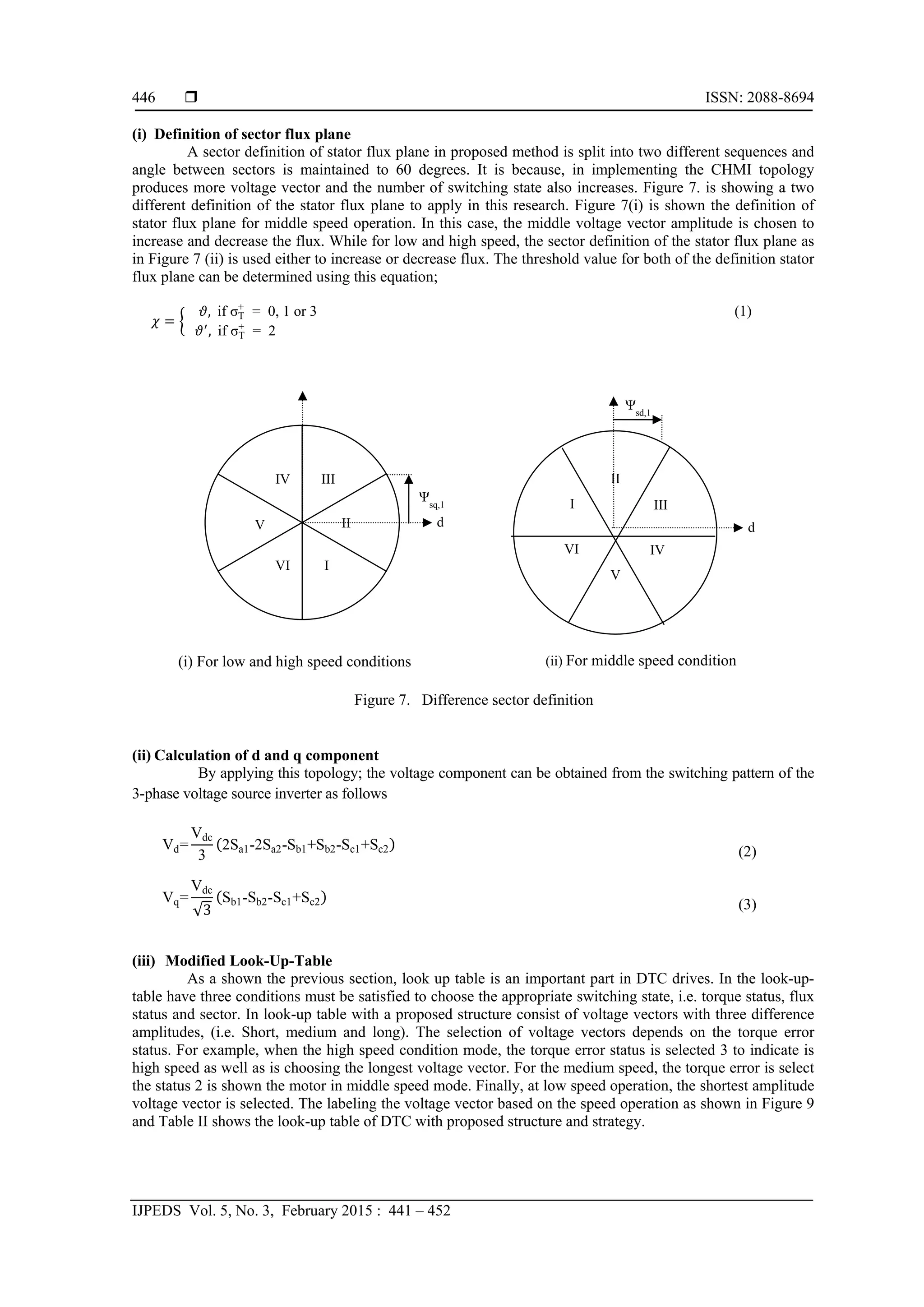
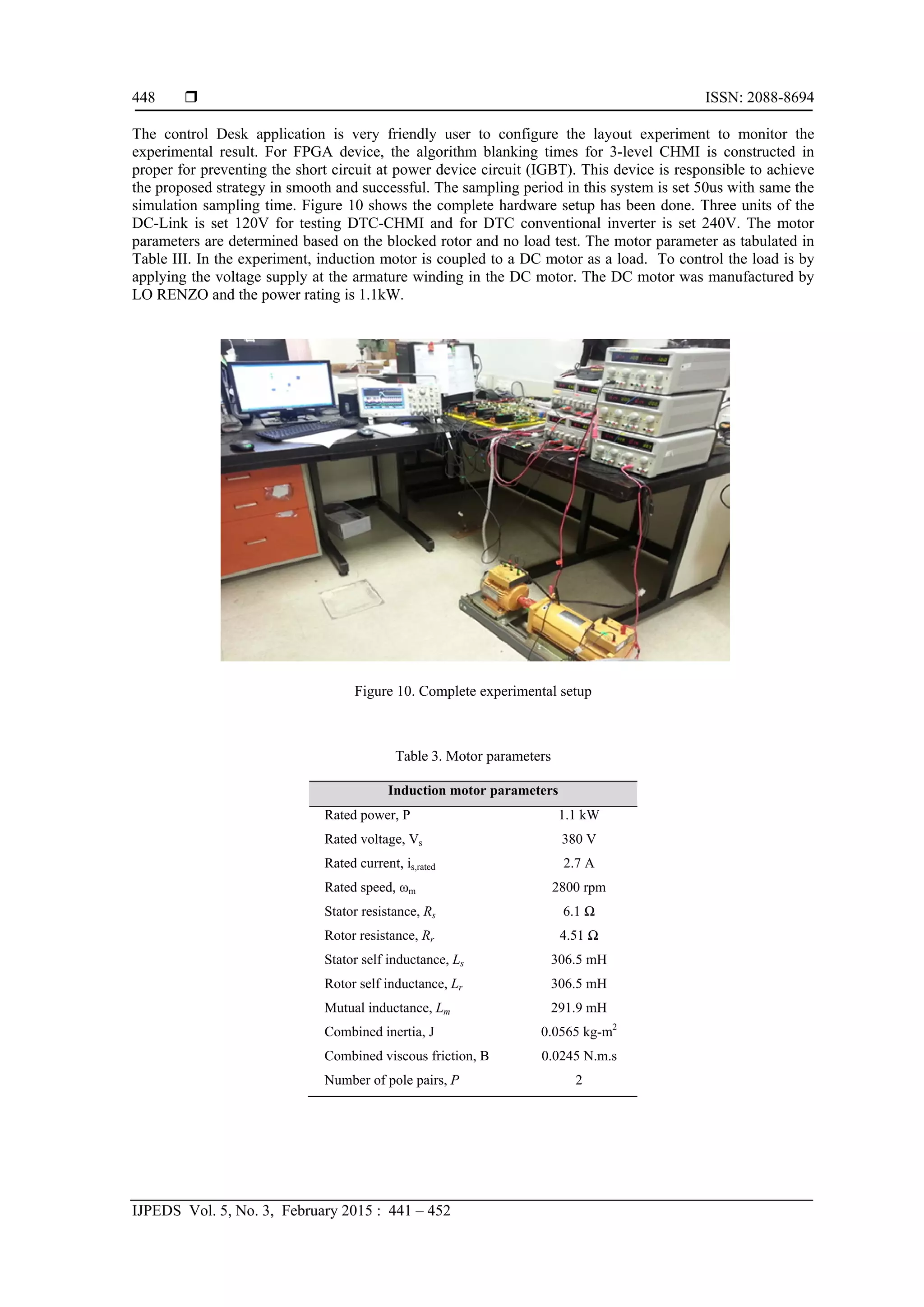
This paper discusses the enhancement of direct torque control (DTC) in three-phase induction machines using a cascaded H-bridge multilevel inverter (CHMI) to improve performance by minimizing torque ripple and reducing switching frequency. The conventional two-level inverter is replaced with the CHMI to allow for greater voltage vector selection, resulting in improved dynamic and steady-state motor performance. Simulation and experimental results confirm the advantages of the proposed method in controlling torque and flux efficiently.
![International Journal of Power Electronics and Drive System (IJPEDS)
Vol. 5, No. 3, February 2015, pp. 441~452
ISSN: 2088-8694 441
Journal homepage: http://iaesjournal.com/online/index.php/IJPEDS
Improved Torque Control Performance in Direct Torque
Control using Optimal Switching Vectors
Muhd Zharif Rifqi Zuber Ahmadi1
, Auzani Jidin2
, Maaspaliza Azri3
, Khairi Rahim4
, Tole Sutikno5
1,2,3,4
Faculty of Electrical Engineering, Faculty of Electrical Engineering,Universiti Teknikal Malaysia Melaka
Hang Tuah Jaya,76100 Durian Tunggal, Melaka Malaysia
5
Department of Electrical Engineering, Universitas Ahmad Dahlan, Yogyakarta, Indonesia
Article Info ABSTRACT
Article history:
Received Nov 3, 2014
Revised Jan 6, 2015
Accepted Jan 19, 2015
This paper presents the significant improvement of Direct Torque
Control (DTC) of 3-phases induction machine using a Cascaded H-
Bidge Multilevel Inverter (CHMI). The largest torque ripple and
variable switching frequency are known as the major problem
founded in DTC of induction motor. As a result, it can diminish the
performance induction motor control. Therefore, the conventional 2-
level inverter has been replaced with CHMI the in order to increase
the performance of the motor either in dynamic or steady-state
condition. By using the multilevel inverter, it can produce a more
selection of the voltage vectors. Besides that, it can minimize the
torque ripple output as well as increase the efficiency by reducing the
switching frequency of the inverter. The simulation model of the
proposed method has been developed and tested by using Matlab
software. Its improvements were also verified via experimental
results.
Keyword:
Cascaded H-Bridge
Direct Torque Control
Induction machine
Multilevel Inverter
Switching Vector
Copyright © 2015 Institute of Advanced Engineering and Science.
All rights reserved.
Corresponding Author:
Muhd Zharif Rifqi Zuber Ahmadi
Faculty of Electrical Engineering
Universiti Teknikal Malaysia Melaka
Hang Tuah Jaya, 76100 Durian Tunggal, Melaka Malaysia
Email: zharifrifqi@student.utem.edu.my
1. INTRODUCTION
In the middle 1980’s, a simple control strategy to enhance performance of induction motor was
proposed by Takahashi and Noguchi. The control strategy is popularly known as Direct Torque Control (DTC)
[1]. This method gradually replacing the traditional method of Field Oriented Control (FOC) proposed by
F.Blaskhe [2]. At early stages, the FOC was extensivey used to established the control of AC quantities of
stator flux, currents and voltages by using vector control approach. However, this scheme is complicated due
to the existence of frame transformation, current controller and requires knowledge of machine parameters.
In DTC, the torque and flux are controlled independently, in which their demands are satisfied
simultaneously by choosing suitable voltage vectors according to the digitized status produced from
hysteresis controllers. Unlike the FOC, the torque and flux are controlled based on producing the current
components (d-q axis component of stator current referring to excitation reference frame) which results in
complex mathematical equations.
Despite the DTC simplicity, it is known to have two major problems, namely variable switching
frequency and large torque ripple. These problems that have arisen due to the unpredictable torque and flux](https://image.slidesharecdn.com/17ijpedszharifauzaniv2-171214013623/75/Improved-Torque-Control-Performance-in-Direct-Torque-Control-using-Optimal-Switching-Vectors-1-2048.jpg)
![ ISSN: 2088-8694
IJPEDS Vol. 5, No. 3, February 2015 : 441 – 452
442
control behavior for various operating conditions in hysteresis operation. Obviously, many researchers have
extensively proposed some/minor adjustments to minimize the problems. Space vector modulation technique
is one of the popular methods to overcome the problem. This way is widely used by researchers in order to
achieve greater performance motor as was reported in [3]. The major different between DTC hysteresis based
and DTC-SVM is the how to generate the stator voltage reference. In DTC-SVM, the stator voltage reference
can be produced by calculating within a sampling time[4, 5]. By doing so, it can produce the constant
switching as opposed the DTC-hysteresis based. However, to generate the stator voltage references involve
the complex calculation and burden the processor device. Another improvement used is a variable hysteresis
band. Basically, when reduce the bandwidth hysteresis band, the torque ripple has also become minimize.
Even so, the possibility to select the reverse voltage vector can be occurred whenever the torque changes
rapidly at the extreme conditions (i.e. at very low speeds). This mean, overshoot and undershoot of torque to
vary outside the hysteresis bands might be happened. As a result, the extreme torque ripple is produced due
to the inappropriate selection voltage vector. To improve the switching frequency, the dithering method is
used [6, 7]. This method was applied with injecting the high switching frequency of the error component for
flux and torque. However, it still also not maintains the switching frequency. Furthermore, many kinds of
technique were adopted in DTC drives in order to overcome the problem as well as enhance the excellent
performance of motor drives such as [8, 9].
In recent years, the researches on DTC drives utilizing multilevel inverter become the hot topic for
providing the more excellent and precision of selection voltage vector to improve DTC performance[10-12].
In general, multilevel inverter can be categorized in three layouts, namely, CHMI, neutral point capacitor
multilevel inverter and flying capacitor multilevel inverter as was reported [13, 14] . The all kinds of
multilevel have different configurations, number of switching devices, switching states/vectors and
arrangements. Multilevel inverter can offer significant advantages to improve DTC performance, especially
for medium and high-power voltage application. Furthermore, it also can operate at high voltage and produce
lower harmonic (i.e. slope of voltage changed dv/dt)[15].
In this paper, the DTC performances, in terms of torque ripple, harmonics distortion and switching
frequency were improved by applying appropriate selection of voltage vectors offered in CHMI topology.
The selection of the appropriate vectors depends on the motor operating conditions which inherently
determined by the output status of 7-level of torque hysteresis comparator. The application of simple DTC
structure and fast instantaneous control with high control bandwidth offered in hysteresis based DTC can be
retained. This paper is organized by section as followed; Section II described about the concept of DTC-
hysteresis based, Section III presents the topology and switching vectors available in CHMI topology,
Section IV discusses the proposed selection of vectors in DTC-CHMI; Section VI presents the simulation
results to show the improvements offered and finally Section VII gives the conclusion.
2. CONCEPT OF DTC-HYSTERESIS BASED
DTC has a simple structure configuration as shown in Figure 1, yet it is superior to enhance torque
and flux control, in terms of fast dynamic and reliable control due to the hysteresis operation. By doing so,
the appropriate selection of voltage vectors can independently control both torque and flux. Therefore, it can
offer a faster instantaneous control of torque and flux based. Selection voltage vector or switching state can
be obtained from the look-up table as was tabulated in Table I. Where, in the switching table contains three
main components, namely the status of torque, flux and status flux orientation for selecting the appropriate
switching state. The switching states are choosing based on the requirement of torque and stator flux, either
to increase or decrease and also stator flux sector. In order to make the decision either to increase or decrease
can be obtained from the 3-level and 2-level hysteresis of torque and stator flux, respectively. Besides that,
the estimated value of flux and torque can be produce from the calculation of voltage and current component.
In power circuits, the voltage source inverter is performed by IGBT device. The schematic diagram of 3-
phase voltage source inverter is realized in Figure 2. According to these figures, the inverter has contained
six switch modes to operate in the 3-phase induction machine. Therefore, it can generate eight voltage space
vectors, as illustrated in Figure 3. Each voltage space vector, has a three switching state, [Sa,Sb,Sc]. Six
active voltage vector ( to ) and two non-active or zero voltage vector ( and ) corresponding to [0 0](https://image.slidesharecdn.com/17ijpedszharifauzaniv2-171214013623/75/Improved-Torque-Control-Performance-in-Direct-Torque-Control-using-Optimal-Switching-Vectors-2-2048.jpg)
![IJPEDS ISSN: 2088-8694
Improved Torque Control Performance in Direct Torque Control using … (Muhd Zharif Rifqi Zuber Ahmadi)
443
0] and [1 1 1], respectively. Each switching device must be complementing each other for (upper and lower
switch) to avoid short circuit conditions.
SaVDC
1
0
Sb
1
0
Sc
1
0
d
q
+
-
va
vb
vc
vn
IM
VSI
Figure 2. Schematic diagram of VSI Figure 3. Voltage vectors are generated by
VSI
V3, (110)V4,(010)
V5,(011)
V6,(001) V1,(101)
V2, (100)V7,(111)
V0,(000)
L
U
T
V
S
I
+
MM
Sa
Sb
Sc
Ψsd
Stator flux and electromagnetic torque estimators
-
Te,ref
+
-
Ψs,ref
Te
Ψs
Ψs
+
ETe Tstat
ib
ic
VDC
ia
Sector detection Voltage calculation
Ψsq
vsd
vsq
isd
isq
-+
d-q current calculation
0
1
0
1
-1
HBΨ
HBTe
EΨ
Figure 1. Complete structure of DTC-Hysteresis Based](https://image.slidesharecdn.com/17ijpedszharifauzaniv2-171214013623/75/Improved-Torque-Control-Performance-in-Direct-Torque-Control-using-Optimal-Switching-Vectors-3-2048.jpg)
![ ISSN: 2088-8694
IJPEDS Vol. 5, No. 3, February 2015 : 441 – 452
444
Table 1. Look-up table
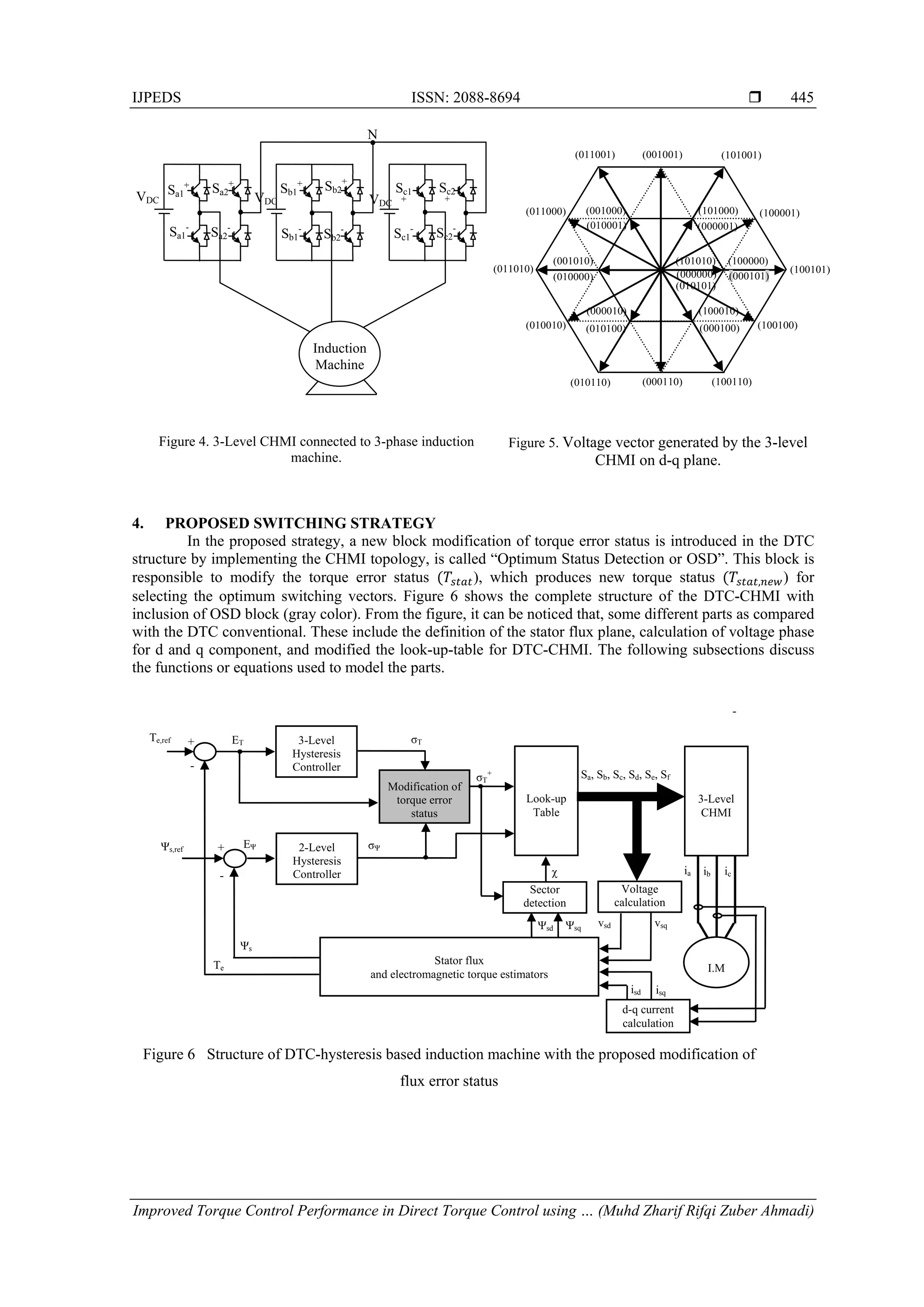
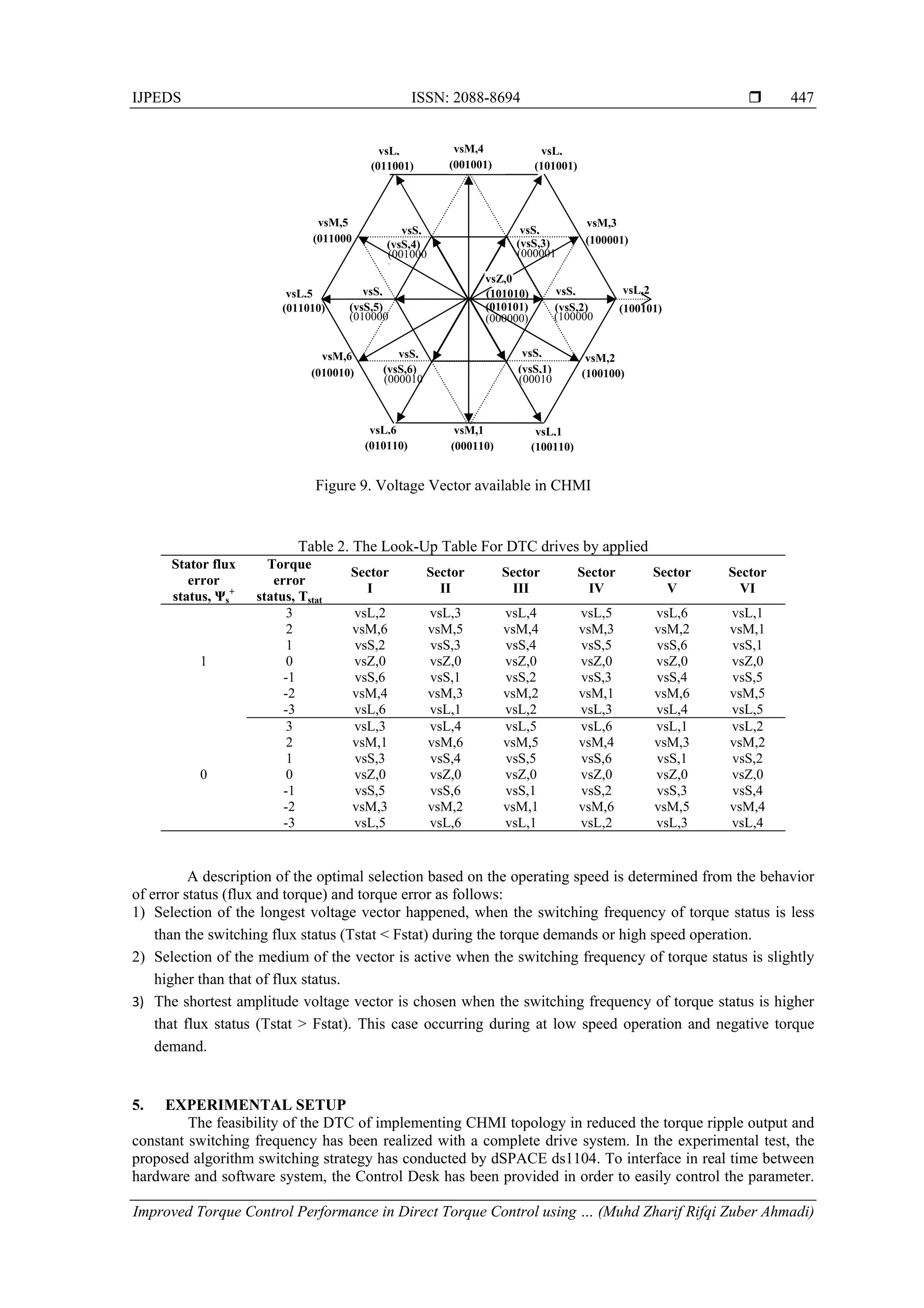
3. CASCADED H-BRIDGE MULTILEVEL INVERTER (CHMI)
CHMI is one of the popular power circuit topologies used in high-power medium voltage. These
names were given because, it uses multiple units of power cells connected in a series to operate in medium or
high voltage as well as to generate lower harmonic ripple. A few isolated DC sources are required for this
inverter to synthesize an output voltage waveform. The structure of this inverter is shown in Figure 4, which
each phase consists of two H-Bridge. Each cell has single DC-link source to fed the induction motor with
connected individually. So, for three phases motor required three isolated DC-links. Four switches off the
device (Sa+, Sa-, Sb+ and Sb-) are operating when they receive the signal from the gate drives. By four
switches of the inverter to trigger, can produce three discrete output Vab with the level +Vdc for (S1 and S4
switch is ON), -Vdc for ( S2 and S3 switch is ON) and 0V for (all switch OFF). The number of voltage level,
L for CHMI can be defined by L=2m+1, where m, for numbers of H-bridge cell per phases. For a 3-level
CHMI, the voltage vector can generate 3 = 27 different voltage vectors and 3L (L - 1) +1= 19 voltage
vectors practices used in CHMI topology. Figure 5 shows the voltage vector available as shown in CHMI on
a d-q axis . It can be seen that, the outer hexagon which contains 12 voltage vectors with single switching
state combination, while for inner hexagon which contains 6 voltage vectors are produced with two
combination switching state. Therefore, when increase the level of multilevel inverter, more voltage vectors
will be produced. So that, the voltage vectors can be categorized in three conditions (i.e: low speed, medium
and high) according the speedy operation. As a result, the total number of switching state become increase,
and it offered the many possibilities to improve control strategies of induction motor.
Stator flux
error
status,
Ψs
+
Torque
error
status,
Tstat
Sec
I
Sec
II
Sec
III
Sec
IV
Sec
V
Sec
VI
1
1 [100] [110] [010] [011] [001] [101]
0 [000] [111] [111] [000] [000] [111]
-1 [001] [101] [100] [110] [010] [011]
0
1 [110] [010] [011] [001] [101] [100]
0 [111] [000] [000] [111] [111] [000]
-1 [011] [001] [101] [100] [110] [101]](https://image.slidesharecdn.com/17ijpedszharifauzaniv2-171214013623/75/Improved-Torque-Control-Performance-in-Direct-Torque-Control-using-Optimal-Switching-Vectors-4-2048.jpg)
![IJPEDS ISSN: 2088-8694
Improved Torque Control Performance in Direct Torque Control using … (Muhd Zharif Rifqi Zuber Ahmadi)
451
7. CONCLUSION
This paper presented a simple implementation by introducing the block modification on DTC of
induction motor fed by 3-level CHMI topology. This multilevel can generate more voltage vectors as well as
increase the number of switching states. Besides that, the appropriate voltage vector was selected based on
the status generated from the modified OSD block. By increasing the number of voltage vectors, it can
improve the DTC performances in term torque ripples, switching frequency and dynamic response. Besides
that, by employing the CHMI topology, the extreme torque slope can be prevented by applying the lower
amplitude vector during at low speed as well as the rate change of voltage can also minimize (dv/dt).
Whereas, in condition at high speed operation, the longest vector is chosen in order to improve torque control
capability in satisfying its demand.
ACKNOWLEDGEMENTS
The authors would like thanks the Ministry of Education Malaysia (KPM) and Universiti Teknikal
Malaysia Melaka (UTeM) for providing the research grant FRGS/2013/FKE/TK02/02/1/F00159 for this research.
REFERENCES
[1] Takahashi, I. and T. Noguchi, A New Quick-Response and High-Efficiency Control Strategy of an Induction Motor.
Industry Applications, IEEE Transactions on, 1986. IA-22(5): p. 820-827.
[2] Ohtani, T., N. Takada, and K. Tanaka. Vector control of induction motor without shaft encoder. in Industry
Applications Society Annual Meeting, 1989., Conference Record of the 1989 IEEE. 1989.
[3] Jun-Koo, K. and S. Seung-Ki. Torque ripple minimization strategy for direct torque control of production motor. in
Industry Applications Conference, 1998. Thirty-Third IAS Annual Meeting. The 1998 IEEE. 1998.
[4] Casadei, D., G. Serra, and A. Tani. Improvement of direct torque control performance by using a discrete SVM
technique. in Power Electronics Specialists Conference, 1998. PESC 98 Record. 29th Annual IEEE. 1998.
[5] Tripathi, A., A.M. Khambadkone, and S.K. Panda, Torque ripple analysis and dynamic performance of a space
vector modulation based control method for AC-drives. Power Electronics, IEEE Transactions on, 2005. 20(2): p.
485-492.
Figure12 Magnified image for all experimental results
(b) Proposed Strategy
(a) Conventional inverter
Ia
Te
vd
IaIa
vd
vd
Ia
Te
Te
vd
Te](https://image.slidesharecdn.com/17ijpedszharifauzaniv2-171214013623/75/Improved-Torque-Control-Performance-in-Direct-Torque-Control-using-Optimal-Switching-Vectors-11-2048.jpg)
![ ISSN: 2088-8694
IJPEDS Vol. 5, No. 3, February 2015 : 441 – 452
452
[6] Noguchi, T., et al., Enlarging switching frequency in direct torque-controlled inverter by means of dithering.
Industry Applications, IEEE Transactions on, 1999. 35(6): p. 1358-1366.
[7] Behera, R.K. and S.P. Das. High performance induction motor drive: A dither injection technique. in Energy,
Automation, and Signal (ICEAS), 2011 International Conference on. 2011.
[8] Bird, I.G. and H. Zelaya-De La Parra, Fuzzy logic torque ripple reduction for DTC based AC drives. Electronics
Letters, 1997. 33(17): p. 1501-1502.
[9] Sutikno, T., et al., An Improved FPGA Implementation of Direct Torque Control for Induction Machines. Industrial
Informatics, IEEE Transactions on, 2013. 9(3): p. 1280-1290.
[10] Ahmadi, M.Z.R.Z., et al. Improved performance of Direct Torque Control of induction machine utilizing 3-level
Cascade H-Bridge Multilevel Inverter. in Electrical Machines and Systems (ICEMS), 2013 International
Conference on. 2013.
[11] Ahmadi, M.Z.R.Z., et al. Minimization of torque ripple utilizing by 3-L CHMI in DTC. in Power Engineering and
Optimization Conference (PEOCO), 2013 IEEE 7th International. 2013.
[12] Alloui, H., A. Berkani, and H. Rezine. A three level NPC inverter with neutral point voltage balancing for
induction motors Direct Torque Control. in Electrical Machines (ICEM), 2010 XIX International Conference on.
2010.
[13] Nabae, A., I. Takahashi, and H. Akagi, A New Neutral-Point-Clamped PWM Inverter. Industry Applications, IEEE
Transactions on, 1981. IA-17(5): p. 518-523.
[14] Malinowski, M., et al., A Survey on Cascaded Multilevel Inverters. Industrial Electronics, IEEE Transactions on,
2010. 57(7): p. 2197-2206.
[15] Ahmadi, M.Z.R.Z., et al. High efficiency of switching strategy utilizing cascaded H-bridge multilevel inverter for
high-performance DTC of induction machine. in Energy Conversion (CENCON), 2014 IEEE Conference on. 2014.](https://image.slidesharecdn.com/17ijpedszharifauzaniv2-171214013623/75/Improved-Torque-Control-Performance-in-Direct-Torque-Control-using-Optimal-Switching-Vectors-12-2048.jpg)