The document presents a sensorless speed control system for an induction motor using a four switch three phase inverter (FSTPI) with direct torque and flux control (DTFC). It introduces an adaptive observer that estimates rotor flux and stator resistance, improving drive performance, especially in low power applications. Simulation and experimental results confirm the method's effectiveness in maintaining accurate speed control and tracking under various operating conditions.
![International Journal of Power Electronics and Drive System (IJPEDS)
Vol. 5, No. 2, October 2014, pp. 153~165
ISSN: 2088-8694 153
Journal homepage: http://iaesjournal.com/online/index.php/IJPEDS
Direct Torque Control of Four Switch Three Phase Inverter
Fed Induction Motor Sensorless Speed Drive
M. K. Metwally
Departement of Electrical Engineering, Menoufiya University, Faculty of Engineering, Menoufiya, Egypt
Article Info ABSTRACT
Article history:
Received Feb 18, 2014
Revised Jul 20, 2014
Accepted Aug 15, 2014
This paper presents sensorless speed control of induction motor (IM) using
four switch three phase inverter (FSTPI) with direct torque and flux control
(DTFC). The proposed sensorless DTFC system consists of an adaptive
observer of rotor flux to accurately estimate stator resistance and speed
simultaneously, without affecting drive performances. The switching
technique for DTFC of IM using FSTPI in low power application is based on
the principle of similarity between FSTPI and SSTPI (six switch three phase
inverter), where the αβ plan is divided into 6 sectors and the formation of the
voltage space vector is done in the same way as for SSTPI by using effective
(mean) vectors. This approach allows using the well-known established
switching table of SSTPI for FSTPI. The simulation results indicates that the
sensorless speed control of FSTPI fed IM with DTFC and adaptive observer
provides accurate estimate, good trajectory tracking with different dynamics
performance. The experimental results verify the effectiveness of the
proposed method at different operating points.
Keyword:
Adaptive flux observer
Direct torque and flux control
Four switch three phase inverter
Induction motor
Sensorless speed control
Stator resistance identification
Copyright © 2014 Institute of Advanced Engineering and Science.
All rights reserved.
Corresponding Author:
M. K. Metwally,
Departement of Electrical Engineering,
Menoufiya University, Faculty of Engineering,
Menoufiya, Egypt.
Email: mohkamel2007@yahoo.com
1. INTRODUCTION
In recent years significant advances have been made on the sensorless control of IM. One of the
most well known methods used for control of AC drives is the Direct Torque Control (DTC). DTC of IM is
known to have a simple control structure with comparable performance to that of the field-oriented control
(FOC) techniques. Unlike FOC methods, DTC techniques require utilization of hysteresis band comparators
instead of flux and torque controllers. To replace the coordinate transformations and pulse width modulation
(PWM) signal generators of FOC, DTC uses look-up tables to select the switching procedure based on the
inverter states [1].
Direct torque control (DTC) of induction motors requires an accurate knowledge of the magnitude
and angular position of the controlled flux. In DTC, the flux is conventionally obtained from the stator
voltage model, using the measured stator voltages and currents. This method, utilizes open loop pure
integration suffering from the well known problems of integration effects in digital systems, especially at low
speeds operation range.
To obtain the simple, effective performances, fast control of torque and flux; a DTFC system for
FSTPI-IM has been proposed [2]. In this paper, the optimal switching look-up table is established with four
basic space vectors of FSTPI and in according with four main sectors in the αβ plan. Comparison with DTFC
of induction motor fed by conventional SSTPI confirm that FSTPI topology can be alternative to the
conventional topology for low power low cost induction motor drives. DTFC method for SSTPI-IM has been](https://image.slidesharecdn.com/0310nov1418jan145645ijpedsid50571edit-171213060634/75/Direct-Torque-Control-of-Four-Switch-Three-Phase-Inverter-Fed-Induction-Motor-Sensorless-Speed-Drive-1-2048.jpg)
![ ISSN: 2088-8694
IJPEDS Vol. 5, No. 2, October 2014 : 153 – 165
154
improved in some researches [3-10], while the torque and speed ripples are reduced. In order to reduce the
speed (torque) ripple, the space vector modulation (SVM) modulator has been used as shown in [5-9].
The switching technique for DTFC-FSTPI-IM in this paper has been done by using the new
approach based on the principle of similarity between FSTPI and SSTPI [5], where the αβ plan is divided
into 6 sectors and the formation of the required reference voltage space vector is done in the same way as for
SSTPI by using effective (mean) vectors.
In the last decade, many researches have been carried on the design of sensorless control schemes of
the IM. Most methods are basically based on the Model Reference Adaptive System schemes (MRAS) [8].
The basic MRAS algorithm is very simple but its greatest drawback is the sensitivity to uncertainties in the
motor parameters. Another method based on the Extended Kalman Filter (EKF) algorithm is used [12-14].
The EKF is a stochastic state observer where nonlinear equations are linearized in every sampling period. An
interesting feature of the EKF is its ability to estimate simultaneously the states and the parameters of a
dynamic process. This is generally useful for both the control and the diagnosis of the process. In [14] the
authors used the EKF algorithm to simultaneously estimate variables and parameters of the IM in healthy
case and under different IM faults. [11] used the Luenberger Observer for state estimation of IM. The
Extended Luenberger Observer (ELO) is a deterministic observer which also linearizes the equations in every
sampling period. There is other type of methods for state estimation that is based on the intelligent techniques
[8].
The proposed sensorless DTFC for FSTPI fed IM showed a good behavior in the transient and
steady states, with an excellent disturbance rejection of the load torque. Simulation and experimental results
demonstrate the effectiveness of the proposed control over different operating conditions, a precise
estimation in low speed regions is obtained.
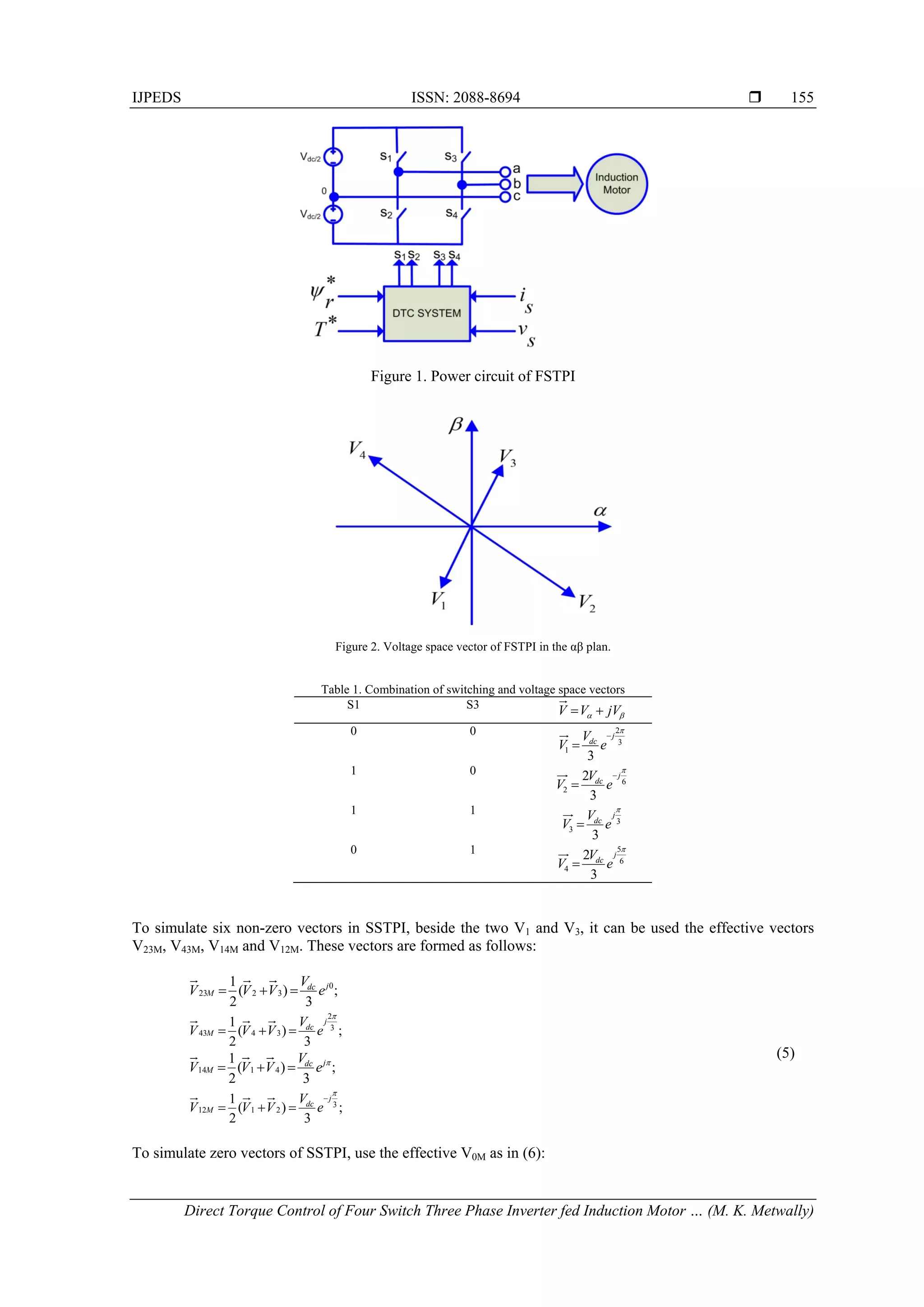
2. Space Vector Analysis of FSTPI
According to the scheme in Figure 1 the switching status is represented by binary variables S1 to S4,
which are set to "1" when the switch is closed and "0" when open. In addition the switches in one inverter
branch are controlled complementary (1 on, 1 off), therefore:
121 SS
(1)
143 SS
Phase to common point voltage depends on the turning off signal of the switch as in (2):
2
)12( 1
dc
ao
V
SV
2
)12( 3
dc
bo
V
SV
0coV
(2)
Combinations of switching S1-S4 result in 4 general space vectors 41 VV (Fig.2, Table 1), components αβ of
the voltage vectors are gained from abc voltages using Clark's transformation as in (3):
c
b
a
V
V
V
V
V
2
3
2
3
0
2
1
2
1
1
3
2
(3)
Where Va, Vb, Vc: output voltages on the load star connection, defined by:
)2(
3
1
boaoa VVV
)2(
3
1
aobob VVV
)(
3
1
boaoc VVV
(4)](https://image.slidesharecdn.com/0310nov1418jan145645ijpedsid50571edit-171213060634/75/Direct-Torque-Control-of-Four-Switch-Three-Phase-Inverter-Fed-Induction-Motor-Sensorless-Speed-Drive-2-2048.jpg)
![ ISSN: 2088-8694
IJPEDS Vol. 5, No. 2, October 2014 : 153 – 165
156
)(
2
1
310 VVV M
(6)
The similarity between space vectors of FSTPI Fig.3 and SSTPI Figure 4 is presented in Table 2.
Figure 3. Voltage space vectors for (FSTPI) on the principle of similarity
Figure 4. Base space vectors in SSTPI
Table 2. Similarity between space vectors of FSTPI and SSTPI
Used voltage space vectors for
SSTPI
Used voltage space vectors for
FSTPI
V1 V23M
V2 V3
V3 V43M
V4 V14M
V5 V1
V6 V12M
V0,V7 V0M
3. Modified Switching Technique for DTC
The objective of the DTC is to keep the motor torque and stator flux within a defined band of
tolerance by selecting the most convenient voltage space vector from (switching table). In the case of the
conventional switching table of DTC for FSTPI-IM, one of four active vectors is chosen (Table 3) [15].](https://image.slidesharecdn.com/0310nov1418jan145645ijpedsid50571edit-171213060634/75/Direct-Torque-Control-of-Four-Switch-Three-Phase-Inverter-Fed-Induction-Motor-Sensorless-Speed-Drive-4-2048.jpg)
![IJPEDS ISSN: 2088-8694
Direct Torque Control of Four Switch Three Phase Inverter fed Induction Motor … (M. K. Metwally)
157
Table 3. Conventional switching table for DTC control method
Δψ ΔT Sector1
-2400
+3300
Sector2
300
+600
Sector3
600
+1500
Sector4
1500
+2400
1 1 V2 V3 V4 V1
1 -1 V1 V2 V3 V4
0 1 V3 V4 V1 V2
0 -1 V4 V1 V2 V3
In order to reduce the torque and speed ripples by using the principle of similarity for voltage space
vectors, optimum switching table in the modified method is established similarly for the SSTPI switching
table. The αβ plan is divided in to six sectors, and for each sector, the optimal space vector is chosen
accordingly to the required torque and flux by using the effective vectors (equations 5, 6). These vectors are
synthesized using the basic space vectors with the duty cycle of 50% (switching period is Ts). The same way
is done for effective zero space vector (Table 4).
Table 4. Modified switching table for DTC control method
Δψ ΔT Sector
I
-300
+300
II
300
+900
III
900
+1500
IV
1500
+2100
V
2100
+2700
VI
2700
+3300
1
1 V3 V43M V14M V1 V12M V23M
-1 V12M V23M V3 V43M V14M V1
0 V13M V13M V13M V13M V13M V13M
-1
1 V43M V14M V1 V12M V23M V3
-1 V1 V12M V23M V3 V43M V14M
0 V13M V13M V13M V13M V13M V13M
The flux and torque calculations remain the same. The stator flux is estimated as follows:
ssssss TRiv )(0
(7)ssssss TRiv )(0
The estimated stator flux s~
and flux angle sector are defined as follows:
s
s
isss arctan;~ 22
(8)
The torque is estimated by the following formula:
ssss ii
P
T
2
3~ (9)
Where: vs,is Stator voltage and current vectors
Rs Stator resistance
P Number of pole pair
T Electromagnetic torque
s Stator flux vector
Ts Sampling time
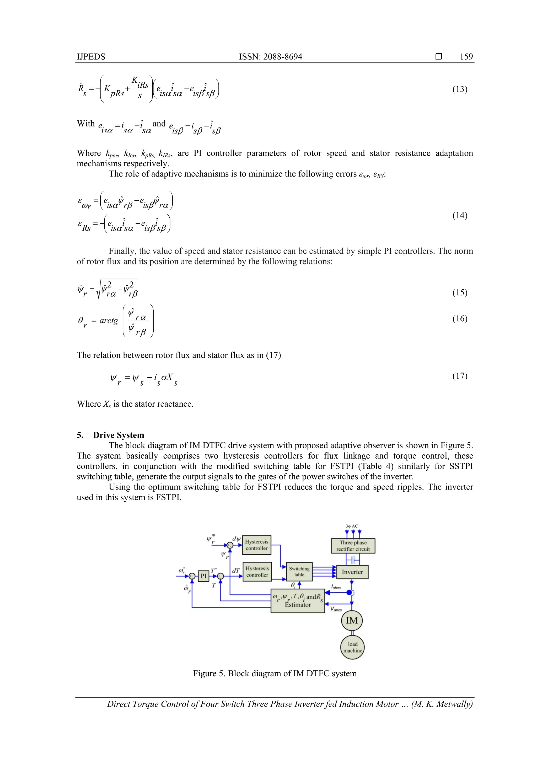
4. Rotor speed, Flux and Stator Resistance Estimation Based Adaptive Observer
To define the adaptive observer, stator voltages and currents are used to estimate the rotor flux (ψr),
speed (ωr), and stator resistance (Rs) according to adaptation laws that must ensure the stability of the system.
Consider then the speed and resistance stator as constant parameters and unknown. The state equation of this
observer is then expressed as follows by separating the state matrix in two, one for the speed and the other for
stator resistance [16].](https://image.slidesharecdn.com/0310nov1418jan145645ijpedsid50571edit-171213060634/75/Direct-Torque-Control-of-Four-Switch-Three-Phase-Inverter-Fed-Induction-Motor-Sensorless-Speed-Drive-5-2048.jpg)
![ ISSN: 2088-8694
IJPEDS Vol. 5, No. 2, October 2014 : 153 – 165
158
)ˆ(ˆ)ˆ()ˆ(
.ˆ
sssRsrr iiKBUXRAAX
(10)
Where
54
54
2311
3211
ˆ0
ˆ0
ˆ0
ˆ0
)ˆ(
aa
aa
aaa
aaa
A
r
r
r
r
r
and
0000
0000
000
000
)ˆ( 6
6
s
s
s
Ra
Ra
RA
K is the observer gain matrix which governs the dynamics and the observer’s robustness; it is calculated as
follows:
T
KKKK
KKKK
K
3412
4321 (11)
The coefficients K1, K2, K3, and K4 are defined as follows:
rrs TTL
kK
1)1(1
)1( 11
rkK ˆ)1( 12
rrs
rrs
TTL
a
k
TTLa
k
K
1)1(1
.
)1(1)1(1)1(
3
1
3
2
1
3
r
a
k
K ˆ
)1(
3
1
4
, k1 > 1
A hat above a symbol in (10) denotes estimated quantities, symbol Tr is the rotor time constant, Ls
stator inductance, Lr rotor inductance and leakage coefficient )/(21
r
L
s
L
m
L . The coefficient k1 is
chosen to impose a dynamic observer faster than the system. The speed adaptive mechanism can be deducted
by the Lyapunov theory [17, 18].
If we choose an adequate candidate function, after application of the Lyapunov theory, the following
adaptation law for the speed is gotten [17–19]:
ris
e
ris
e
s
i
K
p
K
r
ˆˆˆ (12)
While the stator resistance estimation is given by the adaptation law defined by:](https://image.slidesharecdn.com/0310nov1418jan145645ijpedsid50571edit-171213060634/75/Direct-Torque-Control-of-Four-Switch-Three-Phase-Inverter-Fed-Induction-Motor-Sensorless-Speed-Drive-6-2048.jpg)
![ ISSN: 2088-8694
IJPEDS Vol. 5, No. 2, October 2014 : 153 – 165
164
(a) (b)
Figure 13. Experimental results of FSTPI drive at no load (a) Motor Speed; (b) Three-phase motor currents.
(a) (b)
Figure 14. Experimental results of FSTPI drive at no load (a) Motor Speed; (b) Three-phase motor currents.
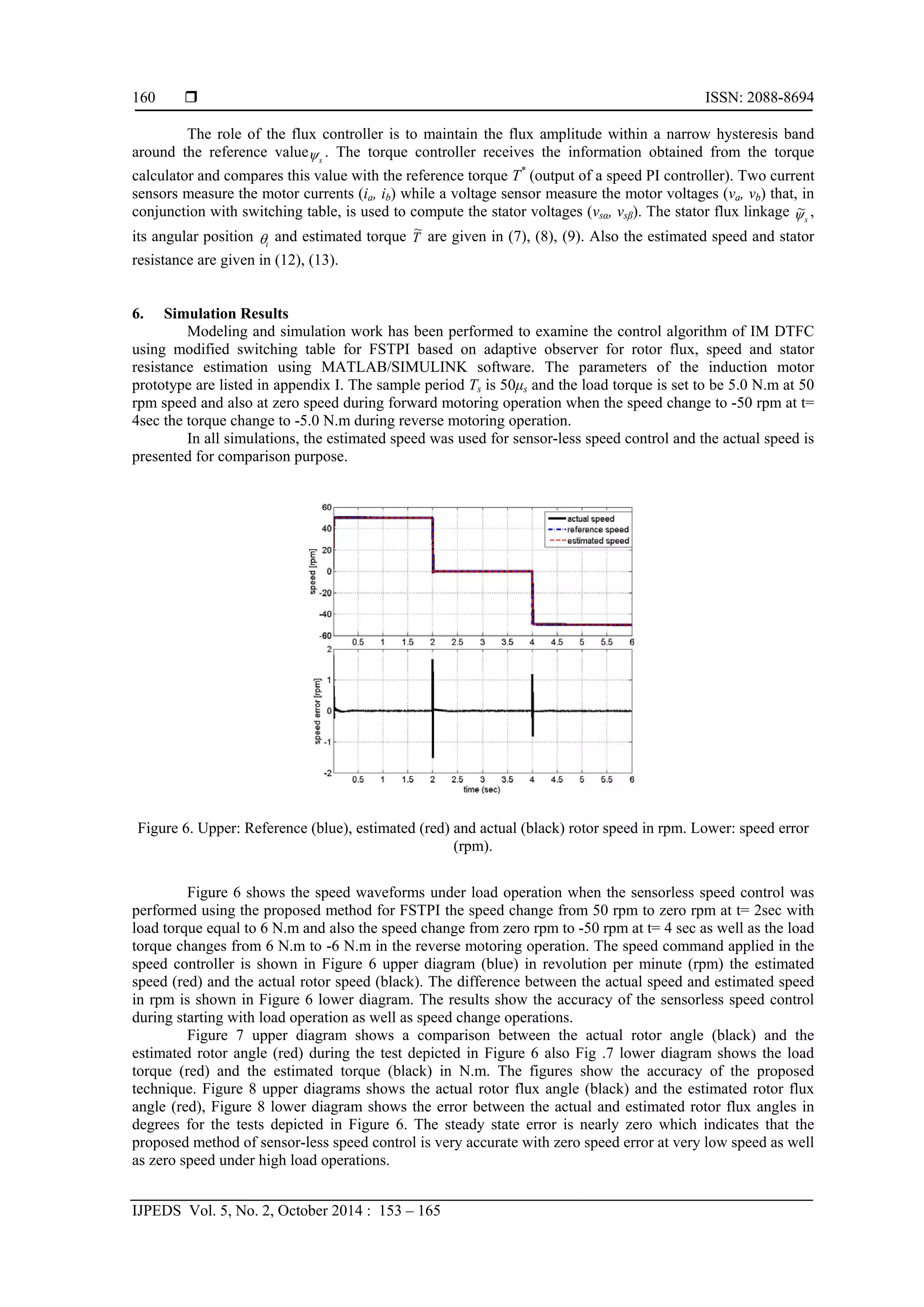
The results shows that a perfect speed tracking with approximately zero steady state error. Figure
14.a shows that the estimated speed follows the reference speed with nearly zero steady state error. While
Figure 14.b shows the motor three phase currents for the step change in speed command.
8. Conclusion
The paper presents a new approach for sensorless speed control of DTFC IM drive system using FSTPI for
low power application. The modified switching table applied in this method is based on the principle of
similarity between FSTPI and SSTPI, where the αβ plan is divided into 6 sectors and the formation of the
voltage space vector is done in the same way as for SSTPI by using effective (mean) vectors. This approach
allows using the well-knowing established switching table of SSTPI for FSTPI, in order to reduce torque
ripples in comparison with the conventional DTC method for FSTPI.
The validity of new technique is verified by simulation and experimental results which demonstrate the
good performance of DTC for FSTPI fed IM, while the good responses of the flux, torque, current and speed
are obtained. Also adaptive flux observer used for rotor flux, speed and stator resistance estimation. The
sensor-less speed control of DTFC of IM using FSTPI strategy provides fast dynamic responses with no
overshoot and negligible steady-state error.
References
[1] Y Zhang., J Zhu., Z Zhao., Wei Xu., and David G. Dorrell. “An Improved Direct Torque Control for Three-Level
Inverter-Fed Induction Motor Sensorless Drive”, IEEE Transactions on Power Electronics, Vol. 27, No. 3, pp.
1502-1513, 2012.](https://image.slidesharecdn.com/0310nov1418jan145645ijpedsid50571edit-171213060634/75/Direct-Torque-Control-of-Four-Switch-Three-Phase-Inverter-Fed-Induction-Motor-Sensorless-Speed-Drive-12-2048.jpg)
![IJPEDS ISSN: 2088-8694
Direct Torque Control of Four Switch Three Phase Inverter fed Induction Motor … (M. K. Metwally)
165
[2] Libo Zheng, John E. Fletcher, Barry W. Williams, and Xiangning He. “A Novel Direct Torque Control Scheme for a
Sensorless Five-Phase Induction Motor Drive”, IEEE Trans. on Industrial Electronics, Vol. 58, No. 2, 2011, pp.
502-513.
[3] Aleksandar Nikolic., and Borislav Jefienic. “Speed Sensorless Direct Torque Control Implementation in a Current
Source Inverter Fed Induction Motor Drive”, 35th
Annual IEEE Power Electronics Specialists Conference, Aachen,
Germany, 2004, pp. 2843-2848.
[4] G. Foo and M. F. Rahman, “Sensorless direct torque and flux-controlled IPM synchronous motor drive at very low
speed without signal injection,” IEEE Trans. Ind. Electron., Vol. 57, no. 1, pp. 395–403, Jan. 2010.
[5] Bassem El Badsi, Badii Bouzidi, and Ahmed Masmoudi, "DTC Scheme for a Four-Switch Inverter-Fed Induction
Motor Emulating the Six-Switch Inverter Operation" IEEE Trans. Power Electronic , Vol 28, no. 7, pp. 3528-3538,
July 2013.
[6] Yen-Shin Lai, Wen-Ke Wang, and Yen-Chang Chen. "Novel switching techniques for reducing the speed ripple of
AC Drives with DTC" IEEE Trans. on Ind Electronics, Vol. 51, No. 4, 2004, pp. 768-775.
[7] P. Q. Dzung, L. M. Phuong, and P. Q. Vinh" A new switching technique for direct torque control of induction motor
using four switch three phase inverter" in proc. IEEE PEDS 2007, pp. 1331-1336.
[8] Cirrincione M., Pucci M., “Sensorless direct torque control of an induction motor by a TLS-based MRAS observer
with adaptive integration,” Automatica, 2005, 41, pp. 1843-1854.
[9] Y. Inoue, Y. Kawaguchi, S. Morimoto, and M. Sanada, “Performance improvement of sensorless IPMSM drives in a
low-speed region using online parameter identification,” IEEE Trans. Ind. Electron., vol. 47, no. 2, pp. 798–804,
Mar./Apr. 2011.
[10] M. Hasegawa and K. Matsui, “Position sensorless control for interior permanent magnet synchronous motor using
adaptive flux observer with inductance identification,” IET Electr. Power Appl., vol. 3, no. 3, pp. 209–217, May
2009.
[11] Kyo B. L., Frede B., “Reduced-Order Extended Luenberger Observer Based Sensorless Vector Control Driven by
Matrix Converter With Nonlinearity Compensation,” IEEE Trans. Ind. Electron., 2006, Vol 53, pp. 66-75.
[12] Jin-Su Jang, Byoung-Gun Park, Tae-Sung Kim, Dong Myung Lee, Dong-Seok Hyun, "Sensorless Control of Four-
Switch Three-Phase PMSM Drive Using Extended Kalman Filter" IEEE IECON Conference, pp.1368-1372, June
2008.
[13] Murat Barut., Seta Bogosyan., and Metin Gokasan, “Speed-Sensorless Estimation for Induction Motors Using
Extended Kalman Filters”, IEEE Transactions on Industrial Electronics, Vol. 54, No. 1, February 2007.
[14] I. M. Alsofyani, NRN Idris, T. Sutikno, and Y. A. Alamri. “An Optimized Extended Kalman Filter for Speed
Sensorless Direct Troque Control of an Induction Motor”, IEEE International Conference on Power and Energy, 2-5
December 2012, Kota Kinabalu Sabah, Malaysia.
[15] Mohamed Azab and A.L. Orille, "Novel Flux and Torque Control of IM Drive using FSTPI", in IEEE Proceeding
IECON conference, 2001,pp 1268 -1273.
[16] Suwankawin S, Sangwongwanich S, “Design strategy of an adaptive full-order observer for speed-sensorless
induction-motor drives-tracking performance and stabilization,” IEEE Trans. on Industrial Electronics, vol. 53, no.
1, pp.96–119, 2006.
[17] Harnefors L, Hinkkanen M, “Complete stability of reduced-order and full-order observers for sensorless IM drives,”
IEEE Trans. on Industrial Electronics 2008; 55(3):1319–1329.
[18] Vaclavek P, Blaha P, “Lyapunov-function-based flux and speed observer for AC induction motor sensorless control
and parameters estimation,” IEEE Trans. on Industrial Electronics 2006; 53(1):138–145.
[19] Etien E, Bensiali N, Chaine C, Champenois G, “Adaptive speed observers for sensorless control of induction motor :
a new criterion of stability,” International Review of Electrical Engineering 2006; 1:36–43.
Appendix I. The parameters of applied induction machine
Parameter Value
Rated power 1 kW
No. of poles 4
Stator resistance 4.85 ohm
Rotor resistance 2.6840 ohm
Rotor leakage inductance 0.0221 H
Stator leakage inductance 0.0221 H
Mutual inductance 0.4114 H
Supply frequency 50 Hz
Motor speed 1420 r.p.m.
Supply voltage 380 volts
Inertia 0.018 kg.m2](https://image.slidesharecdn.com/0310nov1418jan145645ijpedsid50571edit-171213060634/75/Direct-Torque-Control-of-Four-Switch-Three-Phase-Inverter-Fed-Induction-Motor-Sensorless-Speed-Drive-13-2048.jpg)