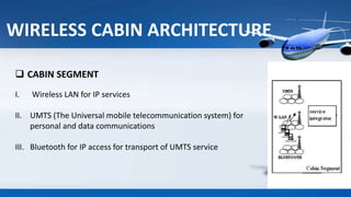
AERONAUTICAL
COMMUNICATION
Presented By
ARUN K.C
EL S5
ROLL NO:23
Reg. No:14042029
OVERVIEW
 Introduction
 Aeronautical communication architecture
 Wireless cabin architecture
 Satellite connection
 Technical overview and table
 Service integrator and dimension
 Advantage
 Disadvantage
 conclusion
INTRODUCTION
 Communication b/w aircraft cabin to the terrestrial network via
satellite segment.
Global coverage is essential for providing continuous service.
 Wireless services such as UMTS, Bluetooth and W-LAN in aircraft cabins.
Airlines are increasingly requiring in-flight services to offer similar
entertainment or business experience to passengers as their terrestrial
counter part.
AERONAUTICAL COMMUNICATION
ARCHITECTURE
WIRELESS CABIN
ARCHITECTURE
GSM telephony is prohibited in commercial
aircraft
TDMA technology
Wireless access technologies
WIRELESS CABIN ARCHITECTURE
 CABIN SEGMENT
I. Wireless LAN for IP services
II. UMTS (The Universal mobile telecommunication system) for
personal and data communications
III. Bluetooth for IP access for transport of UMTS service
WIRELESS CABIN ARCHITECTURE
 SPACE SEGMENT
(Satellite segment)
I. For interconnection of the cabin with the
terrestrial telecom networks.
WIRELESS CABIN ARCHITECTURE
SPACE SEGMENT
WIRELESS CABIN ARCHITECTURE
 GROUND SEGMENT
I. For interconnection to the
terrestrial personal and data
networks as well as the Internet
backbone.
SATELLITE CONNECTION
ARYABHATA CARTOSAT-2C
 The composition of Air traffic
satellite system
 Support the air traffic control and for
weather observations
 Higher reliability, integrity, and operational
continuity are required
SATELLITE CONNECTION
 It will cover the areas especially
over oceanic regions
 Bandwidth
 Geostationary Satellite
TECHNICAL OVERVIEW
 UMTS
(The Universal Mobile Telecommunication System)
Third generation mobile communication system
Developed within the IMT-2000 frameworks
The air interface UTRAN (UMTS terrestrial radio access),applicable in two existence
duplexing scheme-
 UMTS-FDD
 UMTS-TDD
TECHNICAL OVERVIEW
 Coverage range is capacity
dependent that is from 200m to
1.4 km. known as “cell breathing”.
 Maximum bit rate is 2mbps.
TECHNICAL OVERVIEW
 BLUETOOTH
 Operates in 2.4 GHZ ISM band.
 Uses a (Frequency-hopping spread
spectrum) FHSS technique to minimize
interference.
 Has a range 10 meters.
 Bandwidth is 1 MHz
 Maximum bit rate is 1 Mbps.
 WIRELESS-LAN (W-LAN)
 Provides Superior bandwidth compare to any cellular technology
i.e. 26MHz.
 Operates in 2.4GHz ISM band.
 Uses DSSS (Direct sequence spread spectrum) technique to
minimize interference
 Maximum bit rate is 11Mbps.
TECHNICAL OVERVIEW
TECHNICAL OVERVIEW
 Coverage range is 20-100
meters.
Bit rates Bw.(MHz) Band(GHz) Coverage
Range(m.)
Duplexing
Scheme
Tx.P.
(dBm)
Modulation
Max Typ
UMTS 2Mbps 144Kbps 5,10,20 FDD:
1.92-
1.90(ul)
2.11-
2.17(dl)
TDD:
1.90-1.92
2.01-2.025
Depends
on capacity
FDD/TDD 20 QPSK(dL)
BPSK (uL)
Bluetooth1Mbps 728 Kbps 1 2.4-2.4835 10 TDD 0 GFSK
IEEE
802.11b
11Mbps 6,5Mbps 26 2.4-2.4835 20-100 TDD 20 Depends on
bit rate
TABLE OF TECHNICAL OVERVIEW
SERVICE INTEGRATOR AND DIMENSION
INTEGRATOR
 The service integrator will provide the
interfaces for the wireless and wired service
access points in the cabin.
DIMENSION
The system dimensioning process can be
structured in several steps:-
 Determination of gross traffic per aircraft
using the multi-service model.
 Determination of the timely and locally
varying traffic.
ADVANTAGES
 The passengers of both business and economy could use their own wireless
equipment.
 The passengers can be reached under their usual telephone number, they may have
available telephone numbers or other data stored in their cell phones or PDAs
 Their laptops have the software they are used to, the documents they need and with
their personalized configuration (starting web site, bookmarks, address book).
 Saving of the investment that would suppose the installation of terminals (screens,
stations, and wired telephones)
DISADVANTAGES
 It should not be seen an alternative to a wired
architecture in aircraft.
CONCLUSION
Airlines aims at providing various other entertainment and
communication equipment's in the nearest future. Since people are
becoming more attached to the communication resources such as
Network Interface Cards and dial-up connections, airlines have to
accommodate such facilities for the betterment of travel experience. It
focusses on the wireless services such as UMTS and WLAN to connect
the passengers via satellite or terrestrial services. In aeronautical
scenario, global coverage is quite needed for providing a continuous
service. Therefore, satellite communication became indispensable and
together with ever increasing data rate, requirement of applications,
aeronautical communication meets an expensive market.
REFERENCE
• www.wikipedia.com
• www.slideshare.com
• www.youtube.com
THANK

Aeronautical communication seminar presentation

  • 1.
  • 2.
    OVERVIEW  Introduction  Aeronauticalcommunication architecture  Wireless cabin architecture  Satellite connection  Technical overview and table  Service integrator and dimension  Advantage  Disadvantage  conclusion
  • 3.
    INTRODUCTION  Communication b/waircraft cabin to the terrestrial network via satellite segment. Global coverage is essential for providing continuous service.  Wireless services such as UMTS, Bluetooth and W-LAN in aircraft cabins. Airlines are increasingly requiring in-flight services to offer similar entertainment or business experience to passengers as their terrestrial counter part.
  • 4.
  • 5.
    WIRELESS CABIN ARCHITECTURE GSM telephonyis prohibited in commercial aircraft TDMA technology Wireless access technologies
  • 6.
  • 7.
     CABIN SEGMENT I.Wireless LAN for IP services II. UMTS (The Universal mobile telecommunication system) for personal and data communications III. Bluetooth for IP access for transport of UMTS service WIRELESS CABIN ARCHITECTURE
  • 9.
     SPACE SEGMENT (Satellitesegment) I. For interconnection of the cabin with the terrestrial telecom networks. WIRELESS CABIN ARCHITECTURE SPACE SEGMENT
  • 10.
    WIRELESS CABIN ARCHITECTURE GROUND SEGMENT I. For interconnection to the terrestrial personal and data networks as well as the Internet backbone.
  • 11.
  • 12.
     The compositionof Air traffic satellite system  Support the air traffic control and for weather observations  Higher reliability, integrity, and operational continuity are required SATELLITE CONNECTION
  • 13.
    SATELLITE CONNECTION  Itwill cover the areas especially over oceanic regions  Bandwidth  Geostationary Satellite
  • 14.
    TECHNICAL OVERVIEW  UMTS (TheUniversal Mobile Telecommunication System) Third generation mobile communication system Developed within the IMT-2000 frameworks The air interface UTRAN (UMTS terrestrial radio access),applicable in two existence duplexing scheme-  UMTS-FDD  UMTS-TDD
  • 15.
    TECHNICAL OVERVIEW  Coveragerange is capacity dependent that is from 200m to 1.4 km. known as “cell breathing”.  Maximum bit rate is 2mbps.
  • 16.
    TECHNICAL OVERVIEW  BLUETOOTH Operates in 2.4 GHZ ISM band.  Uses a (Frequency-hopping spread spectrum) FHSS technique to minimize interference.  Has a range 10 meters.  Bandwidth is 1 MHz  Maximum bit rate is 1 Mbps.
  • 17.
     WIRELESS-LAN (W-LAN) Provides Superior bandwidth compare to any cellular technology i.e. 26MHz.  Operates in 2.4GHz ISM band.  Uses DSSS (Direct sequence spread spectrum) technique to minimize interference  Maximum bit rate is 11Mbps. TECHNICAL OVERVIEW
  • 18.
    TECHNICAL OVERVIEW  Coveragerange is 20-100 meters.
  • 19.
    Bit rates Bw.(MHz)Band(GHz) Coverage Range(m.) Duplexing Scheme Tx.P. (dBm) Modulation Max Typ UMTS 2Mbps 144Kbps 5,10,20 FDD: 1.92- 1.90(ul) 2.11- 2.17(dl) TDD: 1.90-1.92 2.01-2.025 Depends on capacity FDD/TDD 20 QPSK(dL) BPSK (uL) Bluetooth1Mbps 728 Kbps 1 2.4-2.4835 10 TDD 0 GFSK IEEE 802.11b 11Mbps 6,5Mbps 26 2.4-2.4835 20-100 TDD 20 Depends on bit rate TABLE OF TECHNICAL OVERVIEW
  • 20.
    SERVICE INTEGRATOR ANDDIMENSION INTEGRATOR  The service integrator will provide the interfaces for the wireless and wired service access points in the cabin. DIMENSION The system dimensioning process can be structured in several steps:-  Determination of gross traffic per aircraft using the multi-service model.  Determination of the timely and locally varying traffic.
  • 21.
    ADVANTAGES  The passengersof both business and economy could use their own wireless equipment.  The passengers can be reached under their usual telephone number, they may have available telephone numbers or other data stored in their cell phones or PDAs  Their laptops have the software they are used to, the documents they need and with their personalized configuration (starting web site, bookmarks, address book).  Saving of the investment that would suppose the installation of terminals (screens, stations, and wired telephones)
  • 22.
    DISADVANTAGES  It shouldnot be seen an alternative to a wired architecture in aircraft.
  • 23.
    CONCLUSION Airlines aims atproviding various other entertainment and communication equipment's in the nearest future. Since people are becoming more attached to the communication resources such as Network Interface Cards and dial-up connections, airlines have to accommodate such facilities for the betterment of travel experience. It focusses on the wireless services such as UMTS and WLAN to connect the passengers via satellite or terrestrial services. In aeronautical scenario, global coverage is quite needed for providing a continuous service. Therefore, satellite communication became indispensable and together with ever increasing data rate, requirement of applications, aeronautical communication meets an expensive market.
  • 24.
  • 25.