Downloaded 724 times


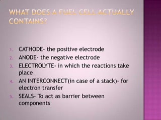

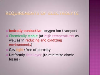
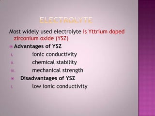

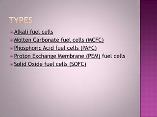
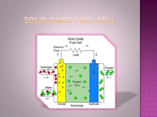

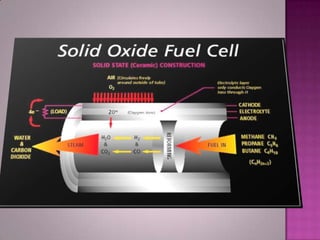

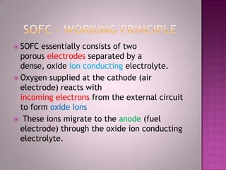
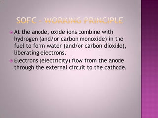


A solid oxide fuel cell (SOFC) works by using oxygen ions conducting through a solid ceramic electrolyte to generate electricity from hydrogen or other fuels. It consists of an anode and cathode separated by an electrolyte, and produces electricity through an electrochemical reaction without combustion. SOFCs operate at high temperatures between 1000-1800 degrees F, which allows them to use a wide variety of fuels. They are more efficient than traditional power generation and are being developed for applications such as stationary power plants, transportation, and residential use.


