Implantation introduction
•Download as PPT, PDF•
3 likes•1,352 views

Ion implantation, SRIM, TRIM introduction

Recommended
More Related Content
What's hot
What's hot (20)
Viewers also liked
Similar to Implantation introduction
Similar to Implantation introduction (20)
Recently uploaded
Recently uploaded (20)
Implantation introduction
- 1. Implantation Introduction, Principle, SRIM & TRIM simulation, Thermal Spike Model and Observations from SRIM K. Kamalakkannan, Research Scholar, Ion Beam Research Lab Department of Nuclear Physics University of Madras, Chennai
- 2. Ion Beam Research Lab, Department of Nuclear Physics Introduction All the electronic equipment needs Semiconducting materials (p-n type). Doping of impurities (carriers) can be processed by two ways- Diffusion and Implantation. Diffusion is limiting process due to saturation limit and so, we can’t make high concentrated carriers. To overcome the diffusion issues of dopants & activation of dopants in material- ion implantation or ion irradiation is the best. In general using particle accelerators to shoot energetic ions on a material is the basic process of implantation and irradiation. Ion implantation is a variety of ion irradiation, as is swift heavy ions irradiation from particle accelerators with very high energies induces ion tracks.
- 3. Ion Beam Research Lab, Department of Nuclear Physics Ion Implantation- Introduction Ion implantation- a materials engineering process by which ions of a material are accelerated in an electrical field and impacted into a solid. This process is used to change the physics, chemical and/or electrical properties of the solid- cause many chemical and physical changes in the target by transferring their energy and momentum to the electrons and atomic nuclei of the target material- causes a structural change, in that the crystal structure of the target. Major components are, 1. Ion source 2. Accelerator 3. Target chamber
- 4. Ion Beam Research Lab, Department of Nuclear Physics Ion Implanter Implantation Structuring Thin Film Deposition Ex: Simulation of B ions in SiC 300 keV
- 5. Ion Beam Research Lab, Department of Nuclear Physics Important parameters and Typical values E q I α A j Φ Ion Energy (eV) Ion Charge Number Ion Current (A) A Angle of Incidence αE,q,I (cm2) (cm-2s-1) Irradiated Area Ion Flux (cm-2)Ion Fluence Remark: “Dose” is often used rather than “Fluence” (although “Dose” should be a volume energy density) Φ = j t j= I qeA (10 to 500 keV) (10 μA to ~30 mA) (60 to 70 ) Ion source: Any element including gas in whole periodic table can be choose Target: Any target matrix can be choose.
- 6. Ion Beam Research Lab, Department of Nuclear Physics Ion- Solid interactions Multiple collision With electrons E= Energy of ions m1, Z1 and m2, Z2= Mass No., At. No. of Incident ions and Target material Rp= Range of ions When energetic ions passes through matter, it looses its energy in two ways, 1. Electronic energy loss due to inelastic collision with electrons(Se) [Electronic stopping] 2. Nuclear energy loss due to elastic collision with atoms of the solid(Sn) [Nuclear stopping] Electronic stopping- Dominant at higher energies (tens of MeV & more)- Swift Heavy ion irradiation (SHI) Nuclear stopping- Dominant at low energies (tens of keV to MeV)
- 7. Ion Beam Research Lab, Department of Nuclear Physics Implantation Simulations- SRIM and TRIM SRIM- The Stopping and Range of Ions in Matter - Group of programs which calculate the stopping and range of ions (up to 2 GeV/amu) into matter using a quantum mechanical treatment of ion-atom collisions. TRIM- The Transport of Ions in Matter - Most comprehensive program, accept complex targets made of compound materials with up to eight layers, each of different materials. It calculate all kinetic phenomena associated with the ion's energy loss: target damage, sputtering, ionization, and phonon production. Based on a Monte-Carlo calculation which follows the ion into the target, making detailed calculations of the energy transferred to every target atom collision. (multi- layer complex targets) Developed by J. F. Ziegler and J. P. Biersack
- 8. Ion Beam Research Lab, Department of Nuclear Physics SRIM calculations: Energy Loss- Stopping powers Stopping powers Sn= dE/dx (Differential energy loss per unit length) Low energy ions <2MeV – elastic collision – nuclear energy loss High energy ions > 2MeV – Inelastic collision – electronic energy loss - SHI. Electronic stopping- (Electronic energy loss) Interaction of heavily charged ions with electrons of the target material through Coulomb forces, produce track of ionization and highly kinetic electrons along the path of the primary ion - latent track (Se>Sth) – Sthdepends on the material. This Electronic stopping forms huge defects (defect clusters, dislocation loop disordered lattice, amorphous etc.) Nuclear Energy loss- Due to elastic collision at lower energies dominant nuclear stopping. This Causes damage and dislocation of nuclei from their lattice sites due to elastic collisions. Always produce lattice defects(Interstitial atoms, anionic or cationic vacancies)
- 9. Ion Beam Research Lab, Department of Nuclear Physics Electronic and Nuclear stopping power- Ex: Aluminum SRIM prediction of electronic and nuclear stopping power of Al ion in different ion energies. Nuclear stopping power is mostly happened for low energy implantation. The lower value of nuclear stopping power is causes the less defects because the higher nuclear stopping power leads atomic displacements.
- 10. Ion Beam Research Lab, Department of Nuclear Physics Thermal Spike Model The energy-loss mechanism of the projectile-ion leads to electronic and atomic collision-cascades This model replaces the complex process of the atomic collision-cascades by an abrupt temperature rise in an infinitesimal cylindrical volume around the ion trajectory at the time-of-passage t = 0. Basic steps of thermal-spike model. (a) Undisturbed solid at temperature T0. (b) At the time-of-passage the tem-perature within a small cylinder rises rapidly to a much higher temperature T »T0. (c) After the passage of the ion, defects are thermally created while the thermal energy gradually dif-fuses away radially from the ion trajectory. (d) Remaining are "frozen" defects.
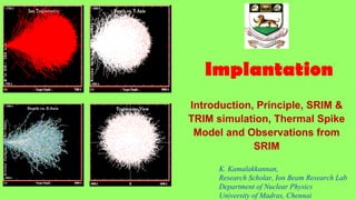
- 11. Ion Beam Research Lab, Department of Nuclear Physics Observations from SRIM and TRIM Ion Range (Rp)= Range of ion Ex: Boron 100 keV in SiC (Rp= 2010 Å) XY Ions Simulation Ex: Boron 100 keV in SiC Damage events Ex: Boron 100 keV in SiC
- 12. Ion Beam Research Lab, Department of Nuclear Physics Observations from SRIM and TRIM Recoil Energy Ex: Al 300 keV in SiC Energy Loss due to ionization Ex: Al 300 keV in SiC Also, 3D views of ion damages, Range of ions, Recoil energy, Phonon and Lateral range distribution XY ions simulations- Lateral, Longitudinal view and Vacancies can be calculated
- 13. Thank You
Editor's Notes
- 60 to 70
- m1, Z1 and m2, Z2=
- (Rp) ÅÅ