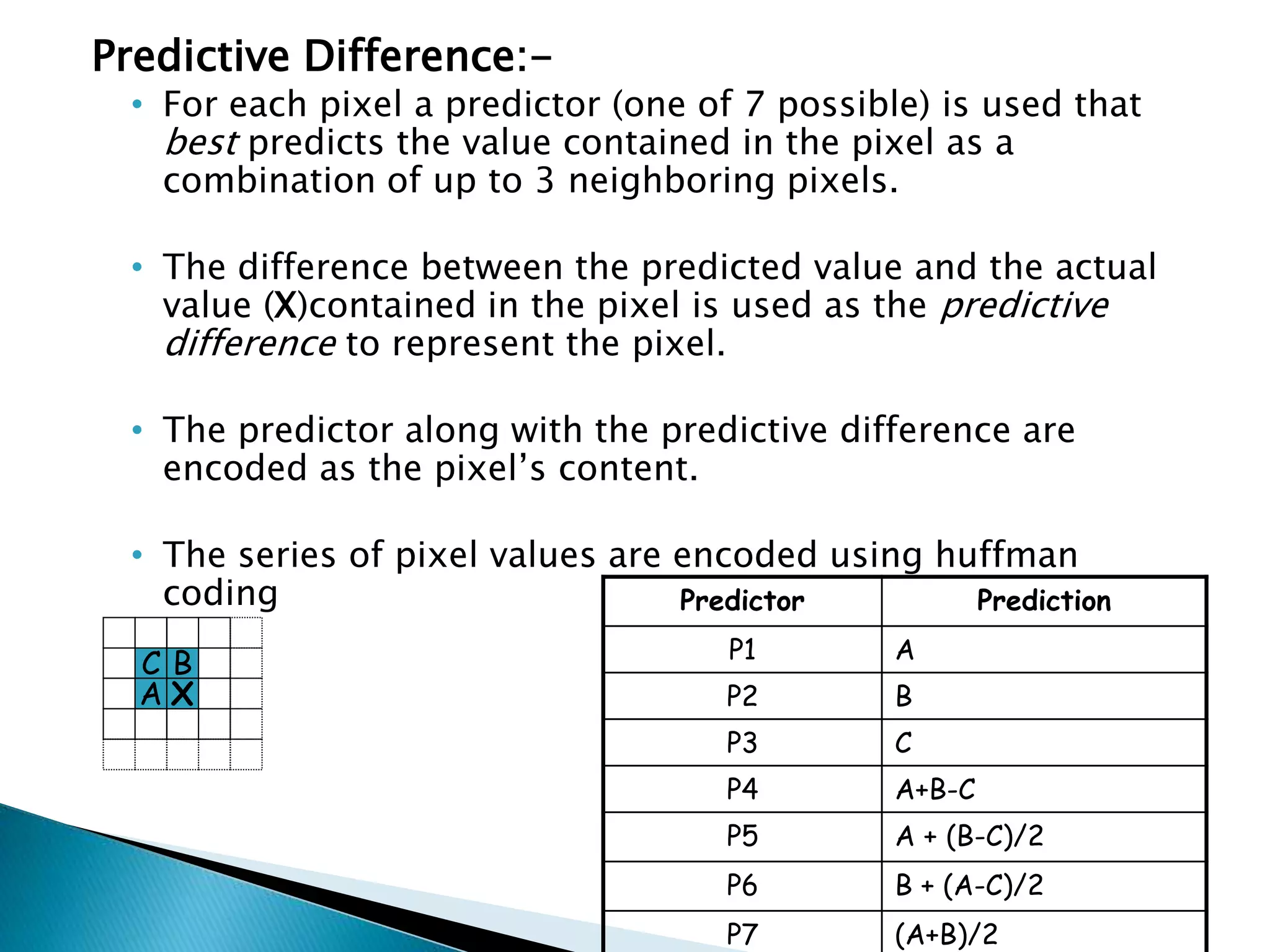
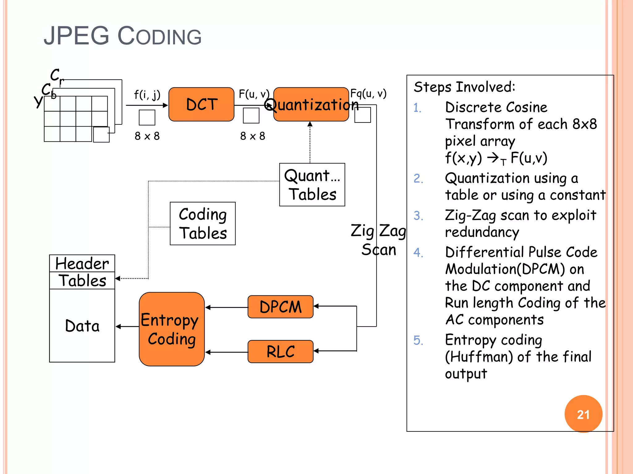
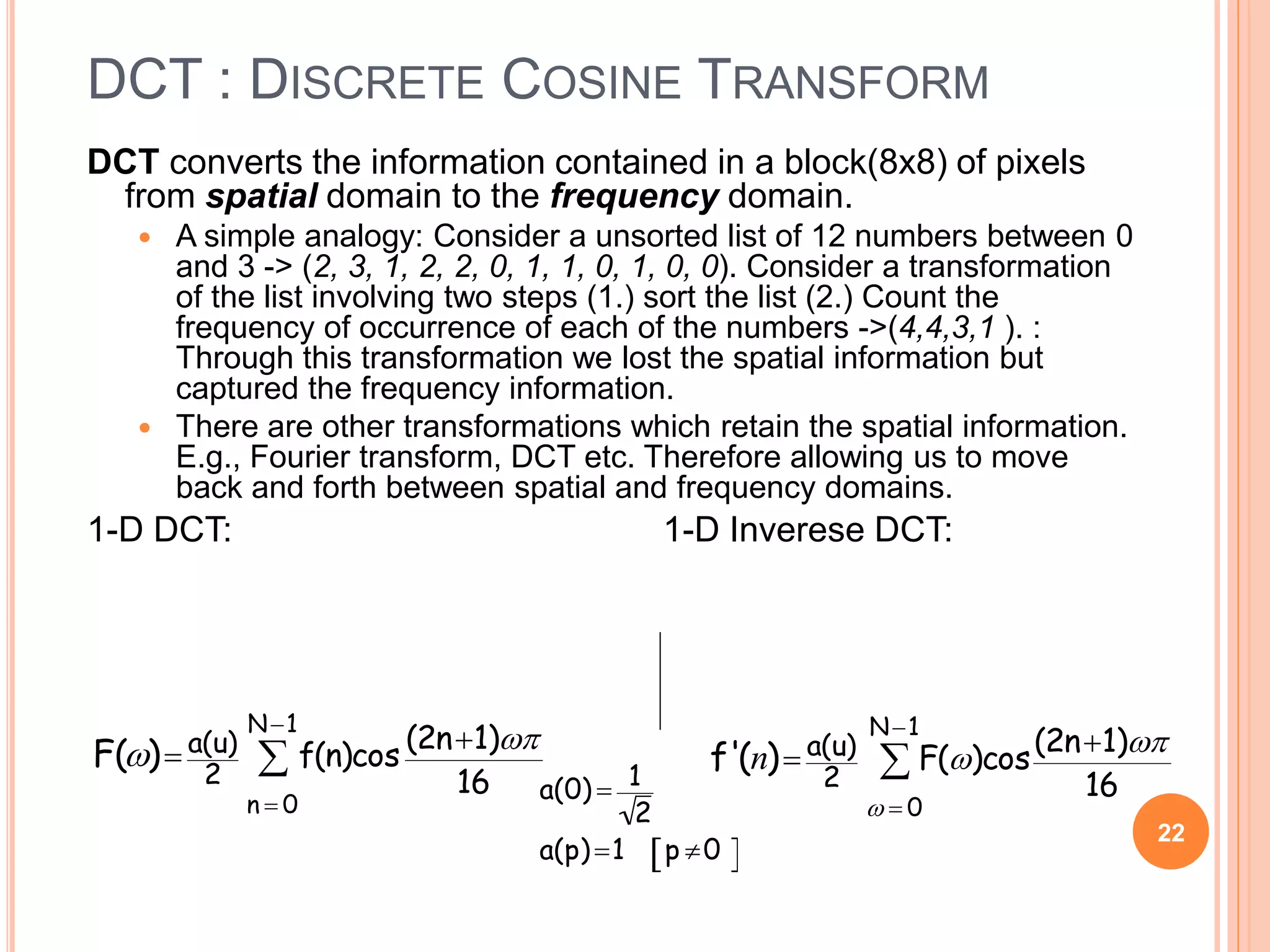
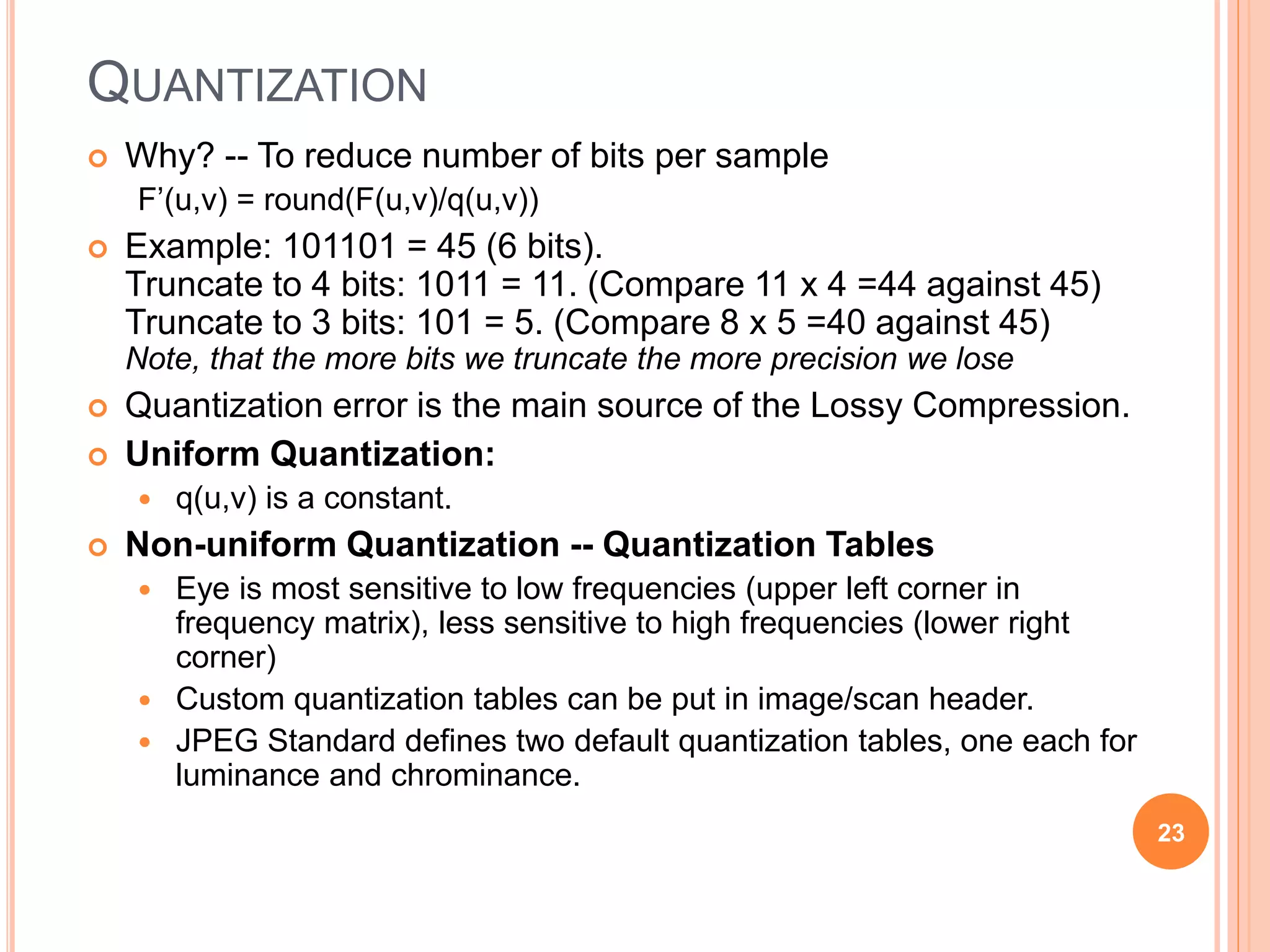
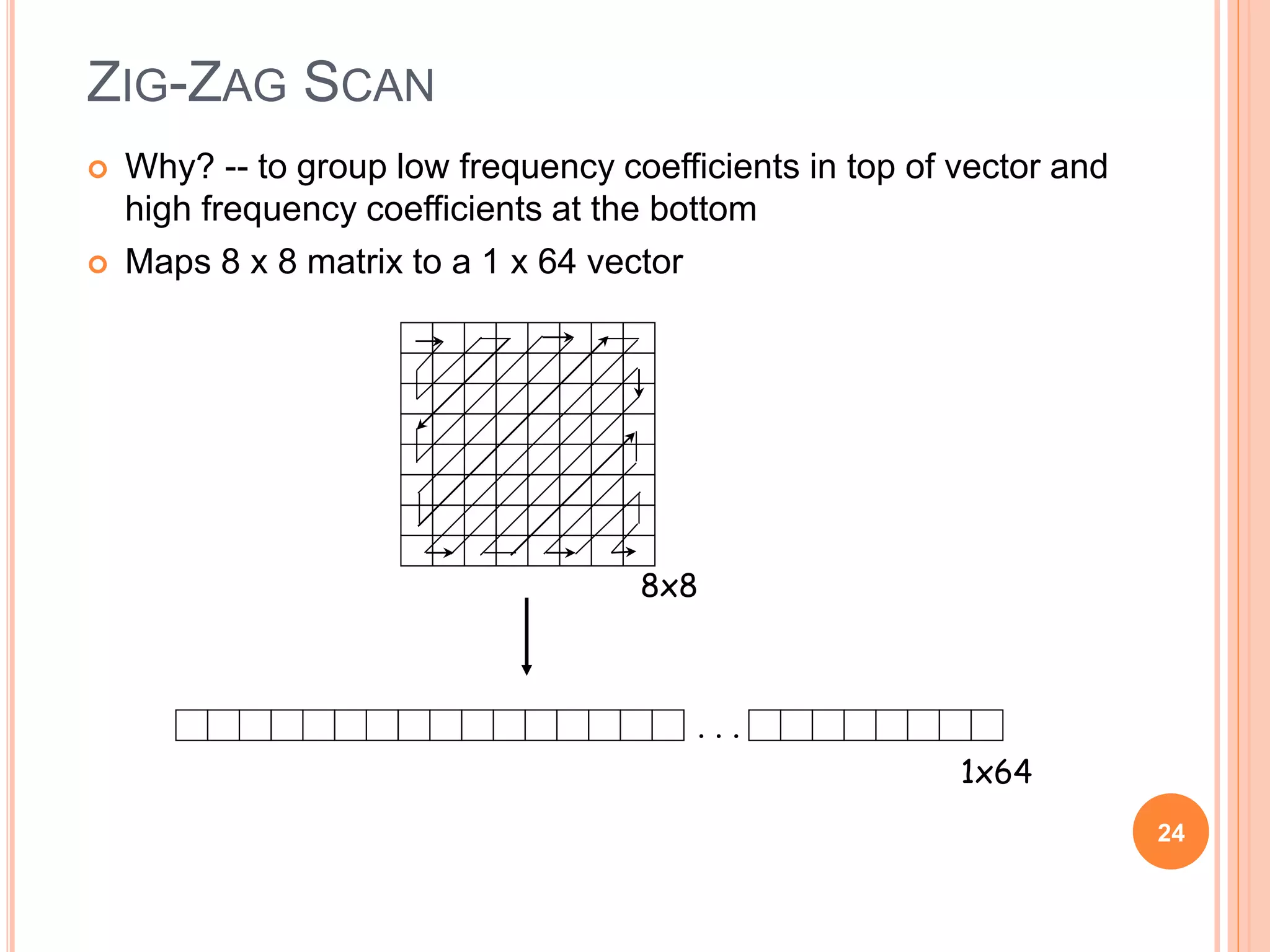
IMAGE
COMPRESSION
&
JPEG
By:
Vividh Tare Tanmay Sarkar
&
Vishwakarma Raj
From SE IT
@
THEEM COLLEGE OF ENGINEERING
IMAGE COMPRESSION
 The objective of image compression is to reduce irrelevance and redundancyof the
image datain order to be able to store or transmit datain an efficient form.
 Image compression maybe lossyor lossless.
 Lossless compression is preferredfor archival purposesand often for medical
imaging, technical drawings, clipart, or comics.
 lossycompression methods, especiallywhenused at low bit rates,
introduce compressionartifacts.
 lossymethods are especiallysuitable for natural images such as photographsin
applications where minor (sometimesimperceptible).
 The image file is converted into a series of binary data,
which is called the bit- stream.
 The decoder receives the encoded bit stream and then
decodes it to re-construct the image.
 The total data quantity of the data bits stream is less than
the total data quantity of the original image.
 Computer graphics can be created by
A) Software package
B) Programs
 These tools provide the graphical representation that are composed of the
various visual objects it too provides the diting of any object or
image……i.e.…circle ,oval, square etc.
 The Graphics is now represented on a high level version for building images
while others that are similar to the source code of a high level program.
 Instead of such high level programs format are being provided in the
Graphical interface.
 These kind of images (compressed) are used on internet specially to save the data for
the user as well as for the compression of graphical images / representation.
 High resolution.
 High quality.
 Can be viewed with any Hardware interface.
 Popular for the way of storing 8-bit scanned or digitized images.
 Has a better compression ratio then any other 8-bit format.
 Color images 24-bit pixels (8-bits each for R,B & G).
 It can show at least 256 colors from the 2 24 colors of the OG image.
 These 256 colors has the 24-bits each with them while the OG has the only 8-bit
with it.
 Its means the ratio of compressing this image is 3:1
 Specially LZW (Lempel-Ziv-Welsh)coding technique is used for the image
compression
 It supports pixel upto 48 bits i.e 16 bitswithR,B & G.
 LZW (Lempel-Ziv-Welsh)coding technique is usedfor theimage compression.
 It toocontains the 256 color table and thetable can be extended upto 4096
entriescontaining same stringofthe pixels that the OG imagehas being
tranferred.
 TIFF wasdesigned tobe the universal bitmapped image format.
 It’sformat is being widelyin the transferringofthe digitizeddocuments
(map/plan)
 It was createdtobecome the standard forthe imagefile exchange.
 It wasa super setofallexisting graphical imagesand the fileformat.
 This kindof image formatwas developed sothat no damaged to thepixel
quality is being done onediting it.
 It can be easilyused withall kindof thesoftware andhardwareconfiguration
easily.
 It’sauniversal losslessdatacompressionalgorithmcreatedbyAbrahamLempel,Jacob Ziv,
andTerryWelch.
 It is thealgorithmofthewidely used Unix file compressionutility compress, andis usedin
theGIF image format.
 LZWcompressionbecame thefirstwidelyuseduniversal datacompressionmethodoncomputers.
 The scenariodescribed byWelch's 1984paper encodessequencesof8-bitdataasfixed-length12-
bitcodes
 Thecodesfrom0 to255represent 1-charactersequencesconsisting ofthe corresponding8-bit
character,andthecodes 256through4095arecreatedin a dictionaryforsequencesencountered
in thedataasit is encoded.
 Ateach stagein compression,inputbytesaregatheredintoa sequenceuntil thenextcharacter
wouldmakea sequenceforwhich thereis no codeyetin thedictionary.
 Thecodeforthe sequence(withoutthatcharacter)is addedtothe output,anda new code(for the
sequencewith thatcharacter)is addedtothe dictionary.
Lossless Compression:-
•Lossless Compression is also called as Data Compaction.
•In lossless Compression, the redundant information contained in the
data is removed.
•Due to removal of such information, there is no loss of the data which
contains information.
•Lossless compression is achieved using those techniques which
generates an exact duplicate of the input data stream, at the receiver.
•Lossless compression is completely a reversible process.
Predictive Difference:-
• For each pixel a predictor (one of 7 possible) is used that
best predicts the value contained in the pixel as a
combination of up to 3 neighboring pixels.
• The difference between the predicted value and the actual
value (X)contained in the pixel is used as the predictive
difference to represent the pixel.
• The predictor along with the predictive difference are
encoded as the pixel’s content.
• The series of pixel values are encoded using huffman
coding
C B
A X
Predictor Prediction
P1 A
P2 B
P3 C
P4 A+B-C
P5 A + (B-C)/2
P6 B + (A-C)/2
P7 (A+B)/2
Lossy Compression:-
 In this type of compression, there is loss of
information in controlled manner.
 Lossy Compression is not a reversible
process.
 We cannot reproduce the duplicate of the
original picture at the receiver.
 The Lossy Compression has higher
compression without a significant loss of
important information.
 The amount of data reduction is possible,by
using Lossy Compression
Orthogonal Transform Coding:-
 KLT(Karhunen-Loeve Transform):-Maximal
Decorrelation process
 DCT(Discrete Cosine Transform):-JPEG is a DCT-
Based image compression standard, which is a
lossy coding method and may result in some loss
of details and unrecoverable distortion.
Subband Coding:-
 DWT(Discrete Wavelet Transform):-To divide the
spectrum of an image into the lowpass and the
highpass components,DWT is a famous
example.JPEG 2000 is a 2-dimension DWT based
image compression standard.
Predictive Coding:-
 DPCM:-To remove mutual reductancy between
successive pixels and encode only the new
information.
.
JPEG compression is used in a number
of image file formats. JPEG/Exif is the
most common image format used by digital
cameras and other photographic image
capture devices; along with JPEG/JFIF, it is
the most common format for storing and
transmitting photographic images on
the World Wide Web. These format
variations are often not distinguished, and
are simply called JPEG
Aphotoofacatwiththe
compressionratedecreasing,
andhencequalityincreasing,
fromlefttoright.
IMAGE COMPRESSION: JPEG
MULTIMEDIA SYSTEMS (MODULE 4 LESSON 1)
19
Summary:
 JPEG Compression
 DCT
 Quantization
 Zig-Zag Scan
 RLE
Sources:
 The JPEG website:
http://www.jpeg.org
 My research notes
 Rajan Bose
WHY JPEG
 The compression ratio of lossless methods (e.g.,
Huffman, Arithmetic, LZW) is not high enough for
image and video compression.
 JPEG uses transform coding, it is largely based on
the following observations:
 Observation 1: A large majority of useful image contents
change relatively slowly across images, i.e., it is unusual for
intensity values to alter up and down several times in a small
area, for example, within an 8 x 8 image block.
A translation of this fact into the spatial frequency domain,
implies, generally, lower spatial frequency components
contain more information than the high frequency
components which often correspond to less useful details and
noises.
 Observation 2: Experiments suggest that humans are more
immune to loss of higher spatial frequency components than
loss of lower frequency components. 20
JPEG CODING
21
Y
Cb
Cr
DPCM
RLC
Entropy
Coding
Header
Tables
Data
Coding
Tables
Quant…
Tables
DCT
f(i, j)
8 x 8
F(u, v)
8 x 8
Quantization
Fq(u, v)
Zig Zag
Scan
Steps Involved:
1. Discrete Cosine
Transform of each 8x8
pixel array
f(x,y) T F(u,v)
2. Quantization using a
table or using a constant
3. Zig-Zag scan to exploit
redundancy
4. Differential Pulse Code
Modulation(DPCM) on
the DC component and
Run length Coding of the
AC components
5. Entropy coding
(Huffman) of the final
output
DCT : DISCRETE COSINE TRANSFORM
DCT converts the information contained in a block(8x8) of pixels
from spatial domain to the frequency domain.
 A simple analogy: Consider a unsorted list of 12 numbers between 0
and 3 -> (2, 3, 1, 2, 2, 0, 1, 1, 0, 1, 0, 0). Consider a transformation
of the list involving two steps (1.) sort the list (2.) Count the
frequency of occurrence of each of the numbers ->(4,4,3,1 ). :
Through this transformation we lost the spatial information but
captured the frequency information.
 There are other transformations which retain the spatial information.
E.g., Fourier transform, DCT etc. Therefore allowing us to move
back and forth between spatial and frequency domains.
1-D DCT: 1-D Inverese DCT:
22

F() a(u)
2
f(n)cos
(2n1)
16
n  0
N1

a(0)  1
2
a(p)1 p 0 

f'(n) a(u)
2
F()cos
(2n1)
16
  0
N1

QUANTIZATION
 Why? -- To reduce number of bits per sample
F’(u,v) = round(F(u,v)/q(u,v))
 Example: 101101 = 45 (6 bits).
Truncate to 4 bits: 1011 = 11. (Compare 11 x 4 =44 against 45)
Truncate to 3 bits: 101 = 5. (Compare 8 x 5 =40 against 45)
Note, that the more bits we truncate the more precision we lose
 Quantization error is the main source of the Lossy Compression.
 Uniform Quantization:
 q(u,v) is a constant.
 Non-uniform Quantization -- Quantization Tables
 Eye is most sensitive to low frequencies (upper left corner in
frequency matrix), less sensitive to high frequencies (lower right
corner)
 Custom quantization tables can be put in image/scan header.
 JPEG Standard defines two default quantization tables, one each for
luminance and chrominance.
23
ZIG-ZAG SCAN
 Why? -- to group low frequency coefficients in top of vector and
high frequency coefficients at the bottom
 Maps 8 x 8 matrix to a 1 x 64 vector
24
8x8
. . .
1x64
Thank You For Your
Patience

Image compression and jpeg

  • 1.
    IMAGE COMPRESSION & JPEG By: Vividh Tare TanmaySarkar & Vishwakarma Raj From SE IT @ THEEM COLLEGE OF ENGINEERING
  • 2.
  • 3.
     The objectiveof image compression is to reduce irrelevance and redundancyof the image datain order to be able to store or transmit datain an efficient form.  Image compression maybe lossyor lossless.  Lossless compression is preferredfor archival purposesand often for medical imaging, technical drawings, clipart, or comics.  lossycompression methods, especiallywhenused at low bit rates, introduce compressionartifacts.  lossymethods are especiallysuitable for natural images such as photographsin applications where minor (sometimesimperceptible).
  • 4.
     The imagefile is converted into a series of binary data, which is called the bit- stream.  The decoder receives the encoded bit stream and then decodes it to re-construct the image.  The total data quantity of the data bits stream is less than the total data quantity of the original image.
  • 6.
     Computer graphicscan be created by A) Software package B) Programs  These tools provide the graphical representation that are composed of the various visual objects it too provides the diting of any object or image……i.e.…circle ,oval, square etc.  The Graphics is now represented on a high level version for building images while others that are similar to the source code of a high level program.  Instead of such high level programs format are being provided in the Graphical interface.
  • 7.
     These kindof images (compressed) are used on internet specially to save the data for the user as well as for the compression of graphical images / representation.  High resolution.  High quality.  Can be viewed with any Hardware interface.  Popular for the way of storing 8-bit scanned or digitized images.  Has a better compression ratio then any other 8-bit format.  Color images 24-bit pixels (8-bits each for R,B & G).  It can show at least 256 colors from the 2 24 colors of the OG image.  These 256 colors has the 24-bits each with them while the OG has the only 8-bit with it.  Its means the ratio of compressing this image is 3:1  Specially LZW (Lempel-Ziv-Welsh)coding technique is used for the image compression
  • 8.
     It supportspixel upto 48 bits i.e 16 bitswithR,B & G.  LZW (Lempel-Ziv-Welsh)coding technique is usedfor theimage compression.  It toocontains the 256 color table and thetable can be extended upto 4096 entriescontaining same stringofthe pixels that the OG imagehas being tranferred.  TIFF wasdesigned tobe the universal bitmapped image format.  It’sformat is being widelyin the transferringofthe digitizeddocuments (map/plan)  It was createdtobecome the standard forthe imagefile exchange.  It wasa super setofallexisting graphical imagesand the fileformat.  This kindof image formatwas developed sothat no damaged to thepixel quality is being done onediting it.  It can be easilyused withall kindof thesoftware andhardwareconfiguration easily.
  • 9.
     It’sauniversal losslessdatacompressionalgorithmcreatedbyAbrahamLempel,JacobZiv, andTerryWelch.  It is thealgorithmofthewidely used Unix file compressionutility compress, andis usedin theGIF image format.  LZWcompressionbecame thefirstwidelyuseduniversal datacompressionmethodoncomputers.  The scenariodescribed byWelch's 1984paper encodessequencesof8-bitdataasfixed-length12- bitcodes  Thecodesfrom0 to255represent 1-charactersequencesconsisting ofthe corresponding8-bit character,andthecodes 256through4095arecreatedin a dictionaryforsequencesencountered in thedataasit is encoded.  Ateach stagein compression,inputbytesaregatheredintoa sequenceuntil thenextcharacter wouldmakea sequenceforwhich thereis no codeyetin thedictionary.  Thecodeforthe sequence(withoutthatcharacter)is addedtothe output,anda new code(for the sequencewith thatcharacter)is addedtothe dictionary.
  • 11.
    Lossless Compression:- •Lossless Compressionis also called as Data Compaction. •In lossless Compression, the redundant information contained in the data is removed. •Due to removal of such information, there is no loss of the data which contains information. •Lossless compression is achieved using those techniques which generates an exact duplicate of the input data stream, at the receiver. •Lossless compression is completely a reversible process.
  • 12.
    Predictive Difference:- • Foreach pixel a predictor (one of 7 possible) is used that best predicts the value contained in the pixel as a combination of up to 3 neighboring pixels. • The difference between the predicted value and the actual value (X)contained in the pixel is used as the predictive difference to represent the pixel. • The predictor along with the predictive difference are encoded as the pixel’s content. • The series of pixel values are encoded using huffman coding C B A X Predictor Prediction P1 A P2 B P3 C P4 A+B-C P5 A + (B-C)/2 P6 B + (A-C)/2 P7 (A+B)/2
  • 14.
    Lossy Compression:-  Inthis type of compression, there is loss of information in controlled manner.  Lossy Compression is not a reversible process.  We cannot reproduce the duplicate of the original picture at the receiver.  The Lossy Compression has higher compression without a significant loss of important information.  The amount of data reduction is possible,by using Lossy Compression
  • 15.
    Orthogonal Transform Coding:- KLT(Karhunen-Loeve Transform):-Maximal Decorrelation process  DCT(Discrete Cosine Transform):-JPEG is a DCT- Based image compression standard, which is a lossy coding method and may result in some loss of details and unrecoverable distortion. Subband Coding:-  DWT(Discrete Wavelet Transform):-To divide the spectrum of an image into the lowpass and the highpass components,DWT is a famous example.JPEG 2000 is a 2-dimension DWT based image compression standard. Predictive Coding:-  DPCM:-To remove mutual reductancy between successive pixels and encode only the new information.
  • 18.
    . JPEG compression isused in a number of image file formats. JPEG/Exif is the most common image format used by digital cameras and other photographic image capture devices; along with JPEG/JFIF, it is the most common format for storing and transmitting photographic images on the World Wide Web. These format variations are often not distinguished, and are simply called JPEG Aphotoofacatwiththe compressionratedecreasing, andhencequalityincreasing, fromlefttoright.
  • 19.
    IMAGE COMPRESSION: JPEG MULTIMEDIASYSTEMS (MODULE 4 LESSON 1) 19 Summary:  JPEG Compression  DCT  Quantization  Zig-Zag Scan  RLE Sources:  The JPEG website: http://www.jpeg.org  My research notes  Rajan Bose
  • 20.
    WHY JPEG  Thecompression ratio of lossless methods (e.g., Huffman, Arithmetic, LZW) is not high enough for image and video compression.  JPEG uses transform coding, it is largely based on the following observations:  Observation 1: A large majority of useful image contents change relatively slowly across images, i.e., it is unusual for intensity values to alter up and down several times in a small area, for example, within an 8 x 8 image block. A translation of this fact into the spatial frequency domain, implies, generally, lower spatial frequency components contain more information than the high frequency components which often correspond to less useful details and noises.  Observation 2: Experiments suggest that humans are more immune to loss of higher spatial frequency components than loss of lower frequency components. 20
  • 21.
    JPEG CODING 21 Y Cb Cr DPCM RLC Entropy Coding Header Tables Data Coding Tables Quant… Tables DCT f(i, j) 8x 8 F(u, v) 8 x 8 Quantization Fq(u, v) Zig Zag Scan Steps Involved: 1. Discrete Cosine Transform of each 8x8 pixel array f(x,y) T F(u,v) 2. Quantization using a table or using a constant 3. Zig-Zag scan to exploit redundancy 4. Differential Pulse Code Modulation(DPCM) on the DC component and Run length Coding of the AC components 5. Entropy coding (Huffman) of the final output
  • 22.
    DCT : DISCRETECOSINE TRANSFORM DCT converts the information contained in a block(8x8) of pixels from spatial domain to the frequency domain.  A simple analogy: Consider a unsorted list of 12 numbers between 0 and 3 -> (2, 3, 1, 2, 2, 0, 1, 1, 0, 1, 0, 0). Consider a transformation of the list involving two steps (1.) sort the list (2.) Count the frequency of occurrence of each of the numbers ->(4,4,3,1 ). : Through this transformation we lost the spatial information but captured the frequency information.  There are other transformations which retain the spatial information. E.g., Fourier transform, DCT etc. Therefore allowing us to move back and forth between spatial and frequency domains. 1-D DCT: 1-D Inverese DCT: 22  F() a(u) 2 f(n)cos (2n1) 16 n  0 N1  a(0)  1 2 a(p)1 p 0   f'(n) a(u) 2 F()cos (2n1) 16   0 N1 
  • 23.
    QUANTIZATION  Why? --To reduce number of bits per sample F’(u,v) = round(F(u,v)/q(u,v))  Example: 101101 = 45 (6 bits). Truncate to 4 bits: 1011 = 11. (Compare 11 x 4 =44 against 45) Truncate to 3 bits: 101 = 5. (Compare 8 x 5 =40 against 45) Note, that the more bits we truncate the more precision we lose  Quantization error is the main source of the Lossy Compression.  Uniform Quantization:  q(u,v) is a constant.  Non-uniform Quantization -- Quantization Tables  Eye is most sensitive to low frequencies (upper left corner in frequency matrix), less sensitive to high frequencies (lower right corner)  Custom quantization tables can be put in image/scan header.  JPEG Standard defines two default quantization tables, one each for luminance and chrominance. 23
  • 24.
    ZIG-ZAG SCAN  Why?-- to group low frequency coefficients in top of vector and high frequency coefficients at the bottom  Maps 8 x 8 matrix to a 1 x 64 vector 24 8x8 . . . 1x64
  • 25.
    Thank You ForYour Patience