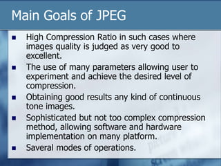
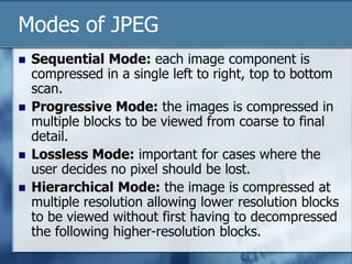
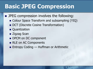
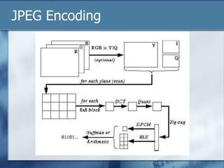
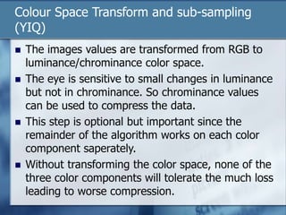
JPEG is a lossy image compression format that works best on continuous-tone images. It uses discrete cosine transform, quantization, zigzag scanning, differential pulse-code modulation, run-length encoding, and Huffman encoding to achieve high compression ratios while maintaining good image quality. Key aspects of JPEG include adjustable compression levels, support for grayscale and color images, and sequential, progressive, lossless, and hierarchical decoding modes.

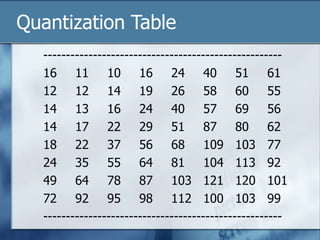
![Quantization Tables
In JPEG, each F[u,v] is divided by a constant q(u,v).
Table of q(u,v) is called quantization table.
Eye is most sensitive to low frequencies (upper left
corner), less sensitive to high frequencies (lower right
corner)
JPEG Standard defines 2 default quantization tables, one
for luminance (below), one for chrominance. E.g Table
below](https://image.slidesharecdn.com/9390681-240223225233-fa312cf5/85/image-processing-for-jpeg-presentati-ppt-12-320.jpg)