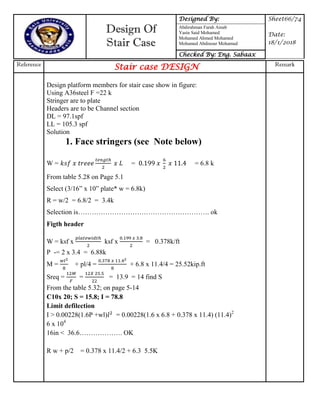
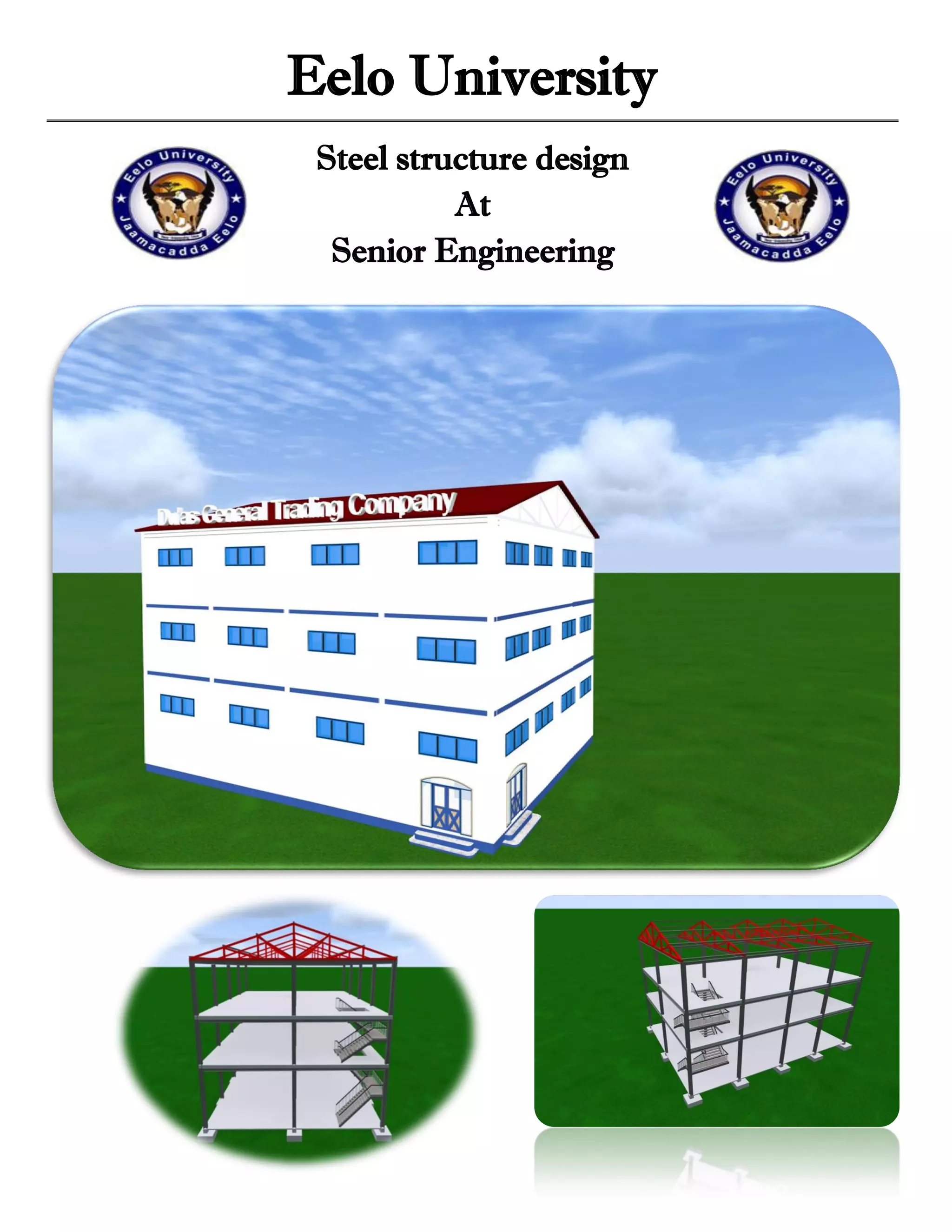
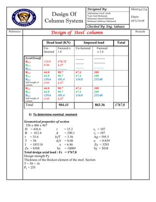
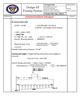
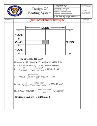
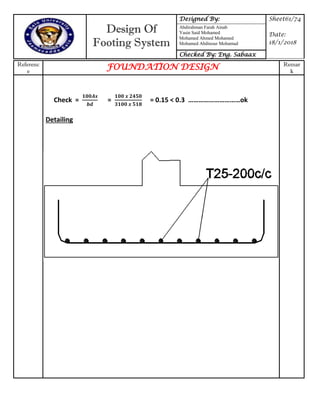
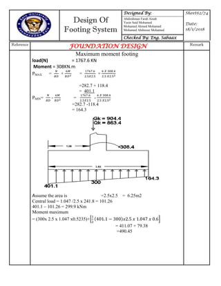
This document appears to be a project report for the design of a steel structure at Eelo University. It includes sections on the design of various structural elements like the roofing system, slabs, beams, columns, connections, footings, and a stair case. The roofing system section provides details on the truss analysis and design of the truss members. The document also discusses the materials and methods used in pre-engineered buildings.


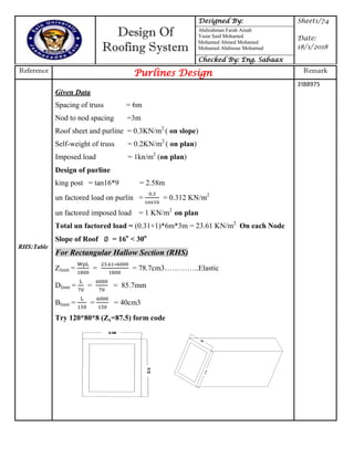
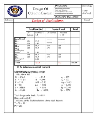
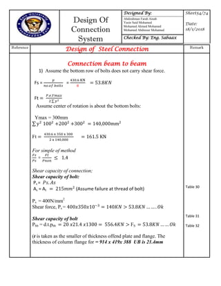
![Design Of
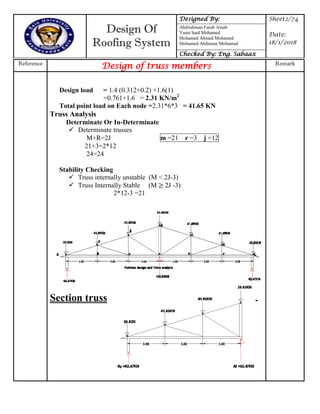
Beam System
Designed By: Sheet19/74
Date:
18/1/2018
Abdirahman Farah Ainab
Yasin Said Mohamed
Mohamed Ahmed Mohamed
Mohamed Abdinour Mohamud
Checked By: Eng. Sabaax
Reference
Design of Steel beam Remark
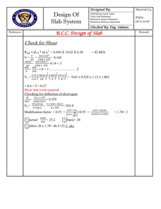
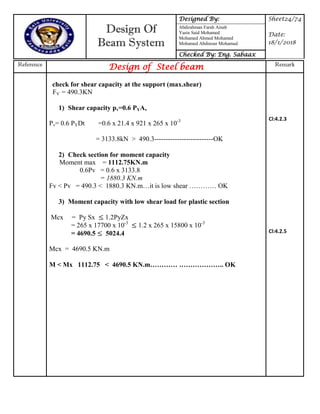
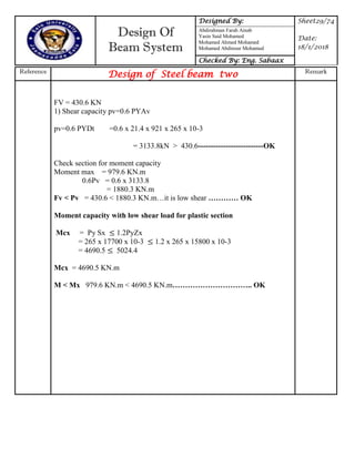
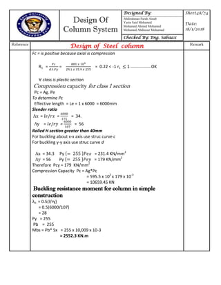
= = 2.25 <2 Two way slab
Self-weight of slab = Ƥc h =0.281x25 .
= 7.025KN/m2
Finishing is Assume to be = 1KN/m2
Self-weight of screed = 0.02x25
=0.5KN/m2
Total dead load on the slab (n) =8.525KN/m2
Dead load of beam from slab = WD = * +
= [
( )
]
= 18.07 x 1.255 = 22.67 x 2 side KN/m
= 45.36 KN/m
Self -weight of beam = 0.98KN/m
Total dead load on the beam = 46.30KN/m
(LL) on Beam from slab (n) WL = [
( )
] = [
( )
]
= 13.4KN/m x 2 sides
= 22.88 KN/m](https://image.slidesharecdn.com/steelbook-180304044203/85/Steel-book-24-320.jpg)
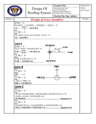
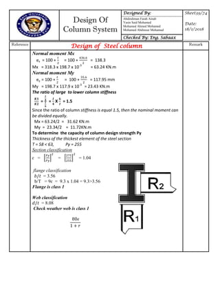
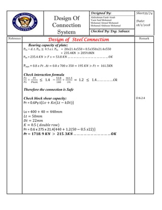
![Design Of
Beam System
Designed By: Sheet25/74
Date:
18/1/2018
Abdirahman Farah Ainab
Yasin Said Mohamed
Mohamed Ahmed Mohamed
Mohamed Abdinour Mohamud
Checked By: Eng. Sabaax
Reference
Design of Steel beam Remark
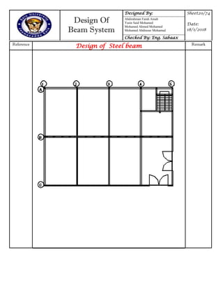
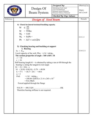
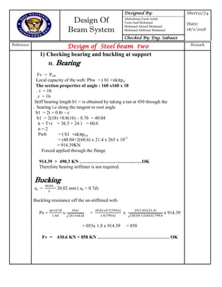
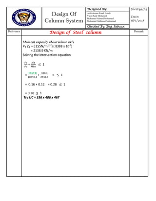
Bucking
ae = 40.04/2 = 20.02 mm ( ae = 0.7d)
Buckling resistance off the un-stiffened web.
Px = x
√
= x
√
x 914.39
= 053x 1.8
= 14,086.5
Fv = 490.3 KN < 858 KN …… ……………………………. OK
Check for deflection under servicebility loads
[
( )
] = 10.6 x 1.255 = 13.3 x 2 = 26.6 KN
E= 205KN/mm2
I= 720000cm4
=* + x104
=* + x104
= 0.16 mm
Limiting lim=span/360 = 9100/360 = 25.27 > 0.16 …………Ok
Cl: 4.5.3.1
Table 8](https://image.slidesharecdn.com/steelbook-180304044203/85/Steel-book-30-320.jpg)
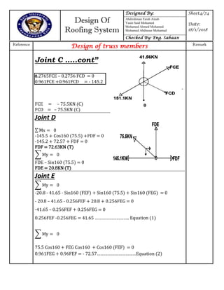
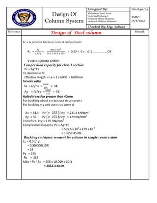
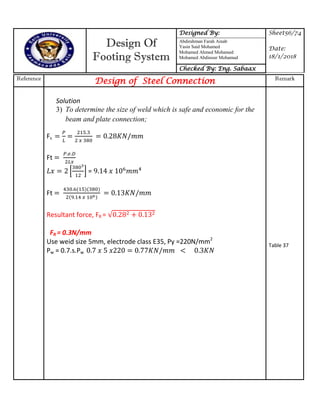
![Design Of
Beam System
Designed By: Sheet26/74
Date:
18/1/2018
Abdirahman Farah Ainab
Yasin Said Mohamed
Mohamed Ahmed Mohamed
Mohamed Abdinour Mohamud
Checked By: Eng. Sabaax
Reference
Design of Steel beam two Remark
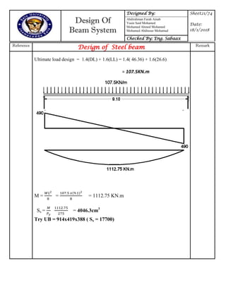
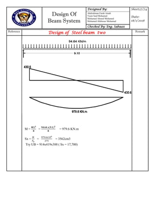
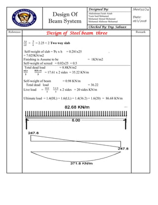
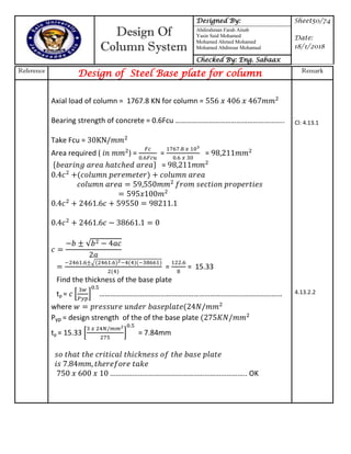
= = 2.25 <2 Two way slab
Self-weight of slab = Ƥc x h = 0.281x25 .
= 7.025KN/m2
Finishing is Assume to be = 1KN/m2
Self-weight of screed = 0.02x25
= 0.5KN/m2
Self-weight of brick wall 18Kgm/m3 x 0.15 x 4
= 10.8KN/m
Total dead load on the slab (n) = 19.325KN/m
Dead load of beam from slab = WD = * +
= [
( )
]
= 40.9 x 1.08 = 51.4 KN/m
Self -weight of beam = 0.98KN/m
Total dead load on the beam = 52.4 KN/m
Live load on Beam from slab (n) WL = [
( )
]
= [
( )
]
= 13.3 KN/m
Ultimate load design = 1.4(DL) + 1.6(LL) = 1.4( 52.4) + 1.6(13.3)
= 94.64 KNm2](https://image.slidesharecdn.com/steelbook-180304044203/85/Steel-book-31-320.jpg)
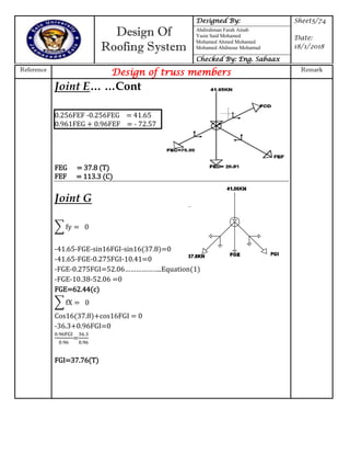
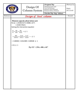
![Design Of
Beam System
Designed By: Sheet30/74
Date:
18/1/2018
Abdirahman Farah Ainab
Yasin Said Mohamed
Mohamed Ahmed Mohamed
Mohamed Abdinour Mohamud
Checked By: Eng. Sabaax
Reference
Design of Steel beam two Remark
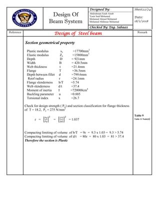
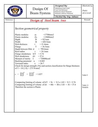
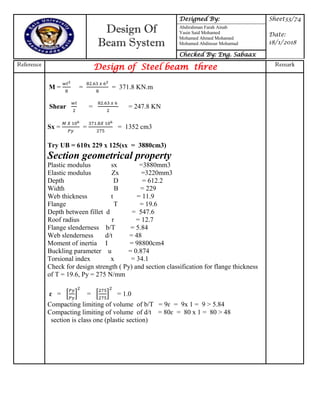
1) Check for deflection under servicebility loads
[
( )
] = 10.6 x 1.255 = 13.3 x 2 = 26.6 KN
E = 205KN/mm2
I = 720000cm4
=* + x104
=* + x104
= 0.16 mm
Limiting lim=span/360 = 9100/360 = 25.27 > 0.16 …………Ok
2) Check for lateral torsional buckling capacity
M
M=950kN
Mlt=0.85
Mb= SxPb =
Pb = uv w
U=0.885
Le= 1.0xL = 1.0x9100 = 9100
Ry= 95.9
𝛌y = 9100/95.9 = 94.8
X = 26.7
𝛌/x = 94.8/26.7 = 3.35
V= 0.89
𝛌 uv w = x x x = 79.5
Py =265 =79.5
Mb = 161x10-3
x17700 = 2849.7
Mb/mlt > M 2849.7/.85 = 3352.5KN > 979.6 KN.m](https://image.slidesharecdn.com/steelbook-180304044203/85/Steel-book-35-320.jpg)

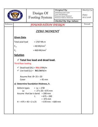
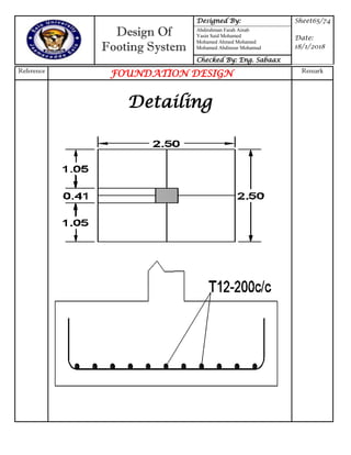
![Design Of
Footing System
Designed By: Sheet60/74
Date:
18/1/2018
Abdirahman Farah Ainab
Yasin Said Mohamed
Mohamed Ahmed Mohamed
Mohamed Abdinour Mohamud
Checked By: Eng. Sabaax
Reference
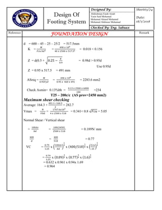
FOUNDATION DESIGN Remark
Shear Check
Checking maximum shear
Vmax= = = 0.275 < 0.8 = 5.05
Normal Shear / Vertical shear
= = = 0.15N/ mm
VC= x ( ) x x ( )
= 0.632 x 0.531 x 1 x 1.17
= 0.4
Punching Shear
Critical perimeter = ( column perimeter + 8 x 1.5d)
= + 8 x 1.5 x 518
= 2461.6 + 6216
= 8677.6 mmVc
Area within perimeter =[ ]
= [ ]
= 3.81 x mm2
Punching shear force = 182( 3.12
– 3.81) = 1055.6KN
Punching shear stress = =
= 0.234
0.234 < 0.4
Check Crack = 3d @ 750mm
= 3 x 518 = 1554 mm > 750mm
Actual distance between =
– –
=
– –
= 353.75mm < 750 mm
H > 200mm](https://image.slidesharecdn.com/steelbook-180304044203/85/Steel-book-66-320.jpg)
![Design Of
Footing System
Designed By: Sheet64/74
Date:
18/1/2018
Abdirahman Farah Ainab
Yasin Said Mohamed
Mohamed Ahmed Mohamed
Mohamed Abdinour Mohamud
Checked By: Eng. Sabaax
Reference
FOUNDATION DESIGN Remark
N = 282.7 X 2.5 (1.047 - 0.518) = 373.87 KN
= = 0.288 < VC = 0.9……..ok
Punching Shear
Critical perimeter = ( column perimeter + 8 x 1.5d)
= 2461.6 + 8 x 1.5 x 518
= 2461.6 + 621.6
= 3083.2 mm
Area within perimeter = [ ]
= [ ]
= 3.81 x mm2
Punching shear force = 282.2 (2.52
– 3.81)
= 688.56KN
Punching shear stress = =
= 0.43
0.43< 0.964
Check Crack = 3d @ 750mm
= 3 x 518 = 1554 mm > 750mm
Actual distance between =
– –
=
– –
= 277.5mm > 750 mm
H > 200mm
Check = = = 0.189< 0.3…………………….OK](https://image.slidesharecdn.com/steelbook-180304044203/85/Steel-book-70-320.jpg)