This document discusses the design principles for retaining walls. It describes:
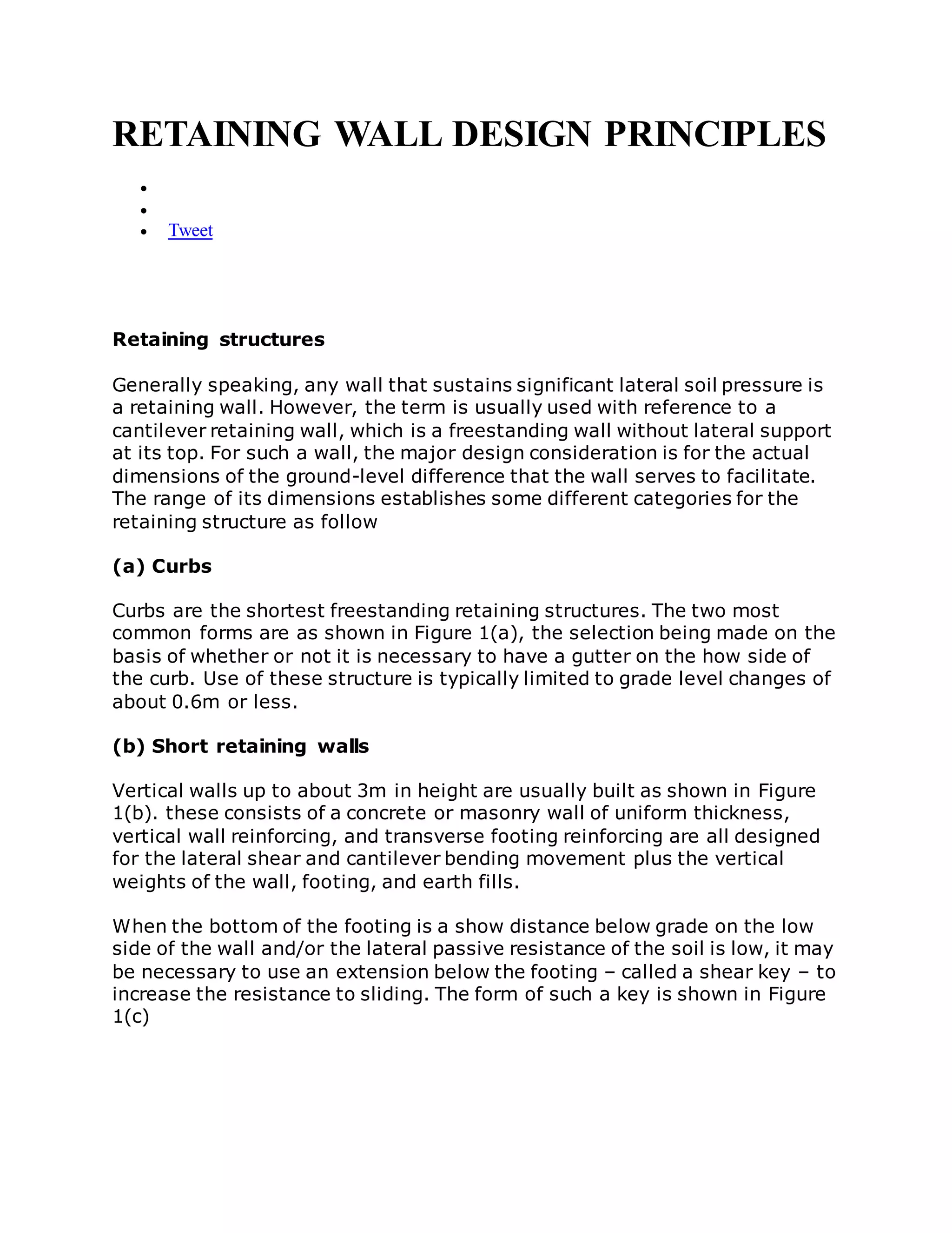
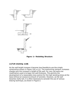
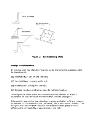
1) Different categories of retaining structures based on height, including curbs under 0.6m, short walls up to 3m using reinforcement, and taller walls requiring bracing.
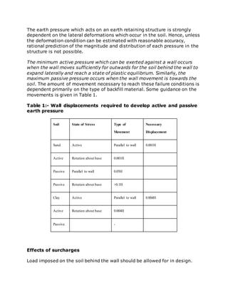
2) Design considerations for stability of soils, the wall itself, structural strength, and effects on adjacent structures.
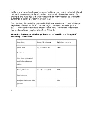
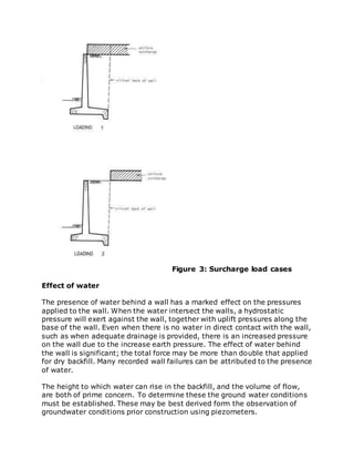
3) Basic loading factors including earth pressures, water pressures, and surcharges from loads or traffic.
4) Considerations for soil properties, selection of backfill material, and effects of groundwater.