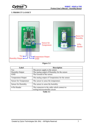
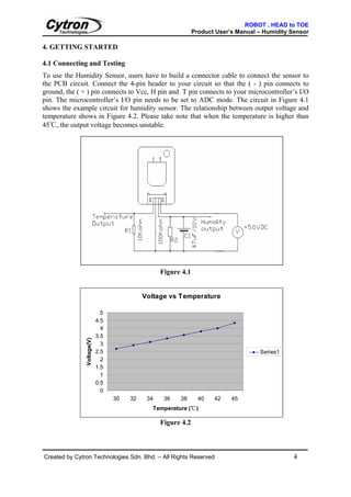
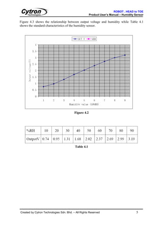
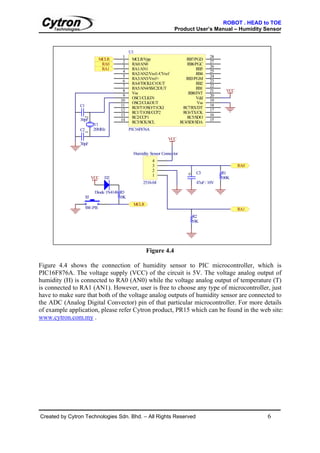
SN-HMD
                                         Humidity Sensor


                                             User’s Manual
                                                               V1.2

                                                     April 2009
Information contained in this publication regarding device applications and the like is intended through suggestion only and may
be superseded by updates. It is your responsibility to ensure that your application meets with your specifications. No
representation or warranty is given and no liability is assumed by Cytron Technologies Incorporated with respect to the accuracy
or use of such information, or infringement of patents or other intellectual property rights arising from such use or otherwise. Use
of Cytron Technologies’s products as critical components in life support systems is not authorized except with express written
approval by Cytron Technologies. No licenses are conveyed, implicitly or otherwise, under any intellectual property rights.
ROBOT . HEAD to TOE
                                                      Product User’s Manual – Humidity Sensor


                                           Index


1. Introduction and Overview                                                             1
2. Product Specification                                                                 2
3. Product Layout                                                                        3
4. Getting Started                                                                       4
5. Warranty                                                                              6


Created by Cytron Technologies Sdn. Bhd. – All Rights Reserved
ROBOT . HEAD to TOE
                                                      Product User’s Manual – Humidity Sensor

1. INTRODUCTION AND OVERVIEW

Humidity sensor is a device consisting of a special plastic material whose electrical
characteristics change according to the amount of humidity in the air. Basically it is a sensor
that senses the amount of water vapor in air. The module of HSM-20G is essential for those
applications where the relative humidity can be converted to standard voltage output. The
applications include:

      •       Humidifiers & dehumidifiers
      •       Air-conditioner
      •       Humidity data loggers
      •       Automotive climate control
      •       Other applications

The product features include:

          •    Voltage analog output for both humidity and temperature.
          •    Small size makes it easy to conceal
          •    Compatible with all types of microcontrollers
          •    High sensitivity to humidity in the air


Created by Cytron Technologies Sdn. Bhd. – All Rights Reserved                           1
ROBOT . HEAD to TOE
                                                                        Product User’s Manual – Humidity Sensor

2. PRODUCT SPECIFICATION

2.1 The specifications of humidity sensor
No.                         Specification                                             Humidity Sensor
1.        Input voltage range                                                 DC 5.0±0.2 V
2.        Output voltage range                                                DC 1.0—3.0 V
3.        Measurement Accuracy                                                ±5% RH
4.        Operating Current (Maximum)                                         2mA
5.        Storage RH Range                                                    0 to 99% RH
6.        Operating RH Range                                                  20 to 95% (100% RH intermittent)
7.        Transient Condensation                                              < 3%RH
8.        Temperature Range:
          - Storage                                                           20℃ to 70℃
          - Operating                                                         0℃ to 50℃
9.        Hysteresis (RH @ 25℃)                                               MAX 2%RH
10.       Long Term Stability (typical drift per year)                        ±1.5%
11.       Linearity                                                           Linearity
12.       Time Response (63% step change)                                     1 min
13.       Dimensions (L*W)                                                    30mm*22mm
                                              Table 2.1

2.2 Pin Definitions and Ratings
    Pin             Name                                                     Function
-             GND                              Connects to Ground
H             Humudity Output                  Voltage analog output.
+             Vcc                              Connects to Vcc (+5V )
T             Temperature Output               Voltage analog output.
Note: Please refer Getting Started for the pin connection
                                                            Table 2.2


Created by Cytron Technologies Sdn. Bhd. – All Rights Reserved                                            2
ROBOT . HEAD to TOE
                                                         Product User’s Manual – Humidity Sensor

 3. PRODUCT LAYOUT


                                                                                        Sensor for
                                                                                        Humidity

                                           Sensor for
                                           Temperature                                    4-Pin
                                                                                          Header


           Vcc                  Temperature Output
Humidity Output                  GND

                                            Figure 3.1

            Label                                        Description
 Vcc                           The power supply to the sensor.
 Humidity Output               The analog output of Humidity for the sensor.
 GND                           The Ground of the sensor.
 Temperature Output            The analog output of Temperature for the sensor.
 Sensor for Temperature        The sensor to sense the temperature.
 Sensor for Humidity           The sensor to sense the humidity.
 4-Pin Header                  The connector to the cable which connect to
                               testing/microcontroller circuit.
                                            Table 3.1


  Created by Cytron Technologies Sdn. Bhd. – All Rights Reserved                           3
ROBOT . HEAD to TOE
                                                               Product User’s Manual – Humidity Sensor

4. GETTING STARTED

4.1 Connecting and Testing
To use the Humidity Sensor, users have to build a connector cable to connect the sensor to
the PCB circuit. Connect the 4-pin header to your circuit so that the ( - ) pin connects to
ground, the ( + ) pin connects to Vcc, H pin and T pin connects to your microcontroller’s I/O
pin. The microcontroller’s I/O pin needs to be set to ADC mode. The circuit in Figure 4.1
shows the example circuit for humidity sensor. The relationship between output voltage and
temperature shows in Figure 4.2. Please take note that when the temperature is higher than
45℃, the output voltage becomes unstable.


                                                  Figure 4.1


                                            Voltage vs Temperature

                              5
                            4.5
                              4
                            3.5
               Voltage(V)


                              3
                            2.5                                                      Series1
                              2
                            1.5
                              1
                            0.5
                              0
                                  30   32    34    36   38       40   42    45
                                              Temperature (℃)

                                                  Figure 4.2


Created by Cytron Technologies Sdn. Bhd. – All Rights Reserved                                   4
ROBOT . HEAD to TOE
                                                       Product User’s Manual – Humidity Sensor

Figure 4.3 shows the relationship between output voltage and humidity while Table 4.1
shows the standard characteristics of the humidity sensor.


                                          Figure 4.2


                                          Table 4.1


Created by Cytron Technologies Sdn. Bhd. – All Rights Reserved                           5
ROBOT . HEAD to TOE
                                                                     Product User’s Manual – Humidity Sensor


                                            U1
                                       1                                                   28
                            MCLR             MCLR/Vpp                        RB7/PGD
                                       2                                                   27
                             RA0             RA0/AN0                          RB6/PGC
                                       3                                                   26
                             RA1             RA1/AN1                               RB5
                                       4                                                   25
                                             RA2/AN2/Vref-/CVref                   RB4
                                       5                                                   24
                                             RA3/AN3/Vref+                   RB3/PGM
                                       6                                                   23
                                             RA4/T0CKI/C1OUT                       RB2
                                       7                                                   22
                                             RA5/AN4/SS/C2OUT                      RB1
                                       8                                                   21      VCC
                                             Vss                              RB0/INT
                                       9                                                   20
                                             OSC1/CLKIN                            Vdd
                                      10                                                   19
                                             OSC2/CLKOUT                           Vss
               C1                     11                                                   18
                                             RC0/T1OSO/T1CKI               RC7/RX/DT
                                      12                                                   17
                                             RC1/T1OSI/CCP2                RC6/TX/CK
                                      13                                                   16
                                             RC2/CCP1                         RC5/SDO
                    2


               30pF                   14                                                   15
                                             RC3/SCK/SCL                  RC4/SDI/SDA
                         Y1
               C2        20MHz              PIC16F876A
                    1


                                                                 VCC
               `
               30pF

                                              Humidity Sensor Connector
                                                         4
                                                         3                                               RA0
                                                         2
                                                                              +     C3           R1
                                                         1
                         VCC   D2                                                                100K
                                                   2510-04                          47uF / 10V

                          Diode 1N4148 R3
                    S5                10K
                                              MCLR
                    SW-PB                                                                                RA1
                                                                                  R2
                                                                                  10K


                                                     Figure 4.4

Figure 4.4 shows the connection of humidity sensor to PIC microcontroller, which is
PIC16F876A. The voltage supply (VCC) of the circuit is 5V. The voltage analog output of
humidity (H) is connected to RA0 (AN0) while the voltage analog output of temperature (T)
is connected to RA1 (AN1). However, user is free to choose any type of microcontroller, just
have to make sure that both of the voltage analog outputs of humidity sensor are connected to
the ADC (Analog Digital Convector) pin of that particular microcontroller. For more details
of example application, please refer Cytron product, PR15 which can be found in the web site:
www.cytron.com.my .


Created by Cytron Technologies Sdn. Bhd. – All Rights Reserved                                                 6
ROBOT . HEAD to TOE
                                                     Product User’s Manual – Humidity Sensor


5. WARRANTY

       Product warranty is valid for 6 months.
       Warranty only applies to manufacturing defect.
       Damage caused by miss-use is not covered under warranty.
       Warranty does not cover freight cost for both ways.


                                       Prepared by
                              Cytron Technologies Sdn. Bhd.
                                19, Jalan Kebudayaan 1A,
                                    Taman Universiti,
                                      81300 Skudai,
                                     Johor, Malaysia.

                                  Tel:    +607-521 3178
                                  Fax:    +607-521 1861

                               URL: www.cytron.com.my
                              Email: support@cytron.com.my
                                      sales@cytron.com.my


Created by Cytron Technologies Sdn. Bhd. – All Rights Reserved                         7

Humidity sensor

  • 1.
    SN-HMD Humidity Sensor User’s Manual V1.2 April 2009 Information contained in this publication regarding device applications and the like is intended through suggestion only and may be superseded by updates. It is your responsibility to ensure that your application meets with your specifications. No representation or warranty is given and no liability is assumed by Cytron Technologies Incorporated with respect to the accuracy or use of such information, or infringement of patents or other intellectual property rights arising from such use or otherwise. Use of Cytron Technologies’s products as critical components in life support systems is not authorized except with express written approval by Cytron Technologies. No licenses are conveyed, implicitly or otherwise, under any intellectual property rights.
  • 2.
    ROBOT . HEADto TOE Product User’s Manual – Humidity Sensor Index 1. Introduction and Overview 1 2. Product Specification 2 3. Product Layout 3 4. Getting Started 4 5. Warranty 6 Created by Cytron Technologies Sdn. Bhd. – All Rights Reserved
  • 3.
    ROBOT . HEADto TOE Product User’s Manual – Humidity Sensor 1. INTRODUCTION AND OVERVIEW Humidity sensor is a device consisting of a special plastic material whose electrical characteristics change according to the amount of humidity in the air. Basically it is a sensor that senses the amount of water vapor in air. The module of HSM-20G is essential for those applications where the relative humidity can be converted to standard voltage output. The applications include: • Humidifiers & dehumidifiers • Air-conditioner • Humidity data loggers • Automotive climate control • Other applications The product features include: • Voltage analog output for both humidity and temperature. • Small size makes it easy to conceal • Compatible with all types of microcontrollers • High sensitivity to humidity in the air Created by Cytron Technologies Sdn. Bhd. – All Rights Reserved 1
  • 4.
    ROBOT . HEADto TOE Product User’s Manual – Humidity Sensor 2. PRODUCT SPECIFICATION 2.1 The specifications of humidity sensor No. Specification Humidity Sensor 1. Input voltage range DC 5.0±0.2 V 2. Output voltage range DC 1.0—3.0 V 3. Measurement Accuracy ±5% RH 4. Operating Current (Maximum) 2mA 5. Storage RH Range 0 to 99% RH 6. Operating RH Range 20 to 95% (100% RH intermittent) 7. Transient Condensation < 3%RH 8. Temperature Range: - Storage 20℃ to 70℃ - Operating 0℃ to 50℃ 9. Hysteresis (RH @ 25℃) MAX 2%RH 10. Long Term Stability (typical drift per year) ±1.5% 11. Linearity Linearity 12. Time Response (63% step change) 1 min 13. Dimensions (L*W) 30mm*22mm Table 2.1 2.2 Pin Definitions and Ratings Pin Name Function - GND Connects to Ground H Humudity Output Voltage analog output. + Vcc Connects to Vcc (+5V ) T Temperature Output Voltage analog output. Note: Please refer Getting Started for the pin connection Table 2.2 Created by Cytron Technologies Sdn. Bhd. – All Rights Reserved 2
  • 5.
    ROBOT . HEADto TOE Product User’s Manual – Humidity Sensor 3. PRODUCT LAYOUT Sensor for Humidity Sensor for Temperature 4-Pin Header Vcc Temperature Output Humidity Output GND Figure 3.1 Label Description Vcc The power supply to the sensor. Humidity Output The analog output of Humidity for the sensor. GND The Ground of the sensor. Temperature Output The analog output of Temperature for the sensor. Sensor for Temperature The sensor to sense the temperature. Sensor for Humidity The sensor to sense the humidity. 4-Pin Header The connector to the cable which connect to testing/microcontroller circuit. Table 3.1 Created by Cytron Technologies Sdn. Bhd. – All Rights Reserved 3
  • 6.
    ROBOT . HEADto TOE Product User’s Manual – Humidity Sensor 4. GETTING STARTED 4.1 Connecting and Testing To use the Humidity Sensor, users have to build a connector cable to connect the sensor to the PCB circuit. Connect the 4-pin header to your circuit so that the ( - ) pin connects to ground, the ( + ) pin connects to Vcc, H pin and T pin connects to your microcontroller’s I/O pin. The microcontroller’s I/O pin needs to be set to ADC mode. The circuit in Figure 4.1 shows the example circuit for humidity sensor. The relationship between output voltage and temperature shows in Figure 4.2. Please take note that when the temperature is higher than 45℃, the output voltage becomes unstable. Figure 4.1 Voltage vs Temperature 5 4.5 4 3.5 Voltage(V) 3 2.5 Series1 2 1.5 1 0.5 0 30 32 34 36 38 40 42 45 Temperature (℃) Figure 4.2 Created by Cytron Technologies Sdn. Bhd. – All Rights Reserved 4
  • 7.
    ROBOT . HEADto TOE Product User’s Manual – Humidity Sensor Figure 4.3 shows the relationship between output voltage and humidity while Table 4.1 shows the standard characteristics of the humidity sensor. Figure 4.2 Table 4.1 Created by Cytron Technologies Sdn. Bhd. – All Rights Reserved 5
  • 8.
    ROBOT . HEADto TOE Product User’s Manual – Humidity Sensor U1 1 28 MCLR MCLR/Vpp RB7/PGD 2 27 RA0 RA0/AN0 RB6/PGC 3 26 RA1 RA1/AN1 RB5 4 25 RA2/AN2/Vref-/CVref RB4 5 24 RA3/AN3/Vref+ RB3/PGM 6 23 RA4/T0CKI/C1OUT RB2 7 22 RA5/AN4/SS/C2OUT RB1 8 21 VCC Vss RB0/INT 9 20 OSC1/CLKIN Vdd 10 19 OSC2/CLKOUT Vss C1 11 18 RC0/T1OSO/T1CKI RC7/RX/DT 12 17 RC1/T1OSI/CCP2 RC6/TX/CK 13 16 RC2/CCP1 RC5/SDO 2 30pF 14 15 RC3/SCK/SCL RC4/SDI/SDA Y1 C2 20MHz PIC16F876A 1 VCC ` 30pF Humidity Sensor Connector 4 3 RA0 2 + C3 R1 1 VCC D2 100K 2510-04 47uF / 10V Diode 1N4148 R3 S5 10K MCLR SW-PB RA1 R2 10K Figure 4.4 Figure 4.4 shows the connection of humidity sensor to PIC microcontroller, which is PIC16F876A. The voltage supply (VCC) of the circuit is 5V. The voltage analog output of humidity (H) is connected to RA0 (AN0) while the voltage analog output of temperature (T) is connected to RA1 (AN1). However, user is free to choose any type of microcontroller, just have to make sure that both of the voltage analog outputs of humidity sensor are connected to the ADC (Analog Digital Convector) pin of that particular microcontroller. For more details of example application, please refer Cytron product, PR15 which can be found in the web site: www.cytron.com.my . Created by Cytron Technologies Sdn. Bhd. – All Rights Reserved 6
  • 9.
    ROBOT . HEADto TOE Product User’s Manual – Humidity Sensor 5. WARRANTY Product warranty is valid for 6 months. Warranty only applies to manufacturing defect. Damage caused by miss-use is not covered under warranty. Warranty does not cover freight cost for both ways. Prepared by Cytron Technologies Sdn. Bhd. 19, Jalan Kebudayaan 1A, Taman Universiti, 81300 Skudai, Johor, Malaysia. Tel: +607-521 3178 Fax: +607-521 1861 URL: www.cytron.com.my Email: support@cytron.com.my sales@cytron.com.my Created by Cytron Technologies Sdn. Bhd. – All Rights Reserved 7