Download to read offline

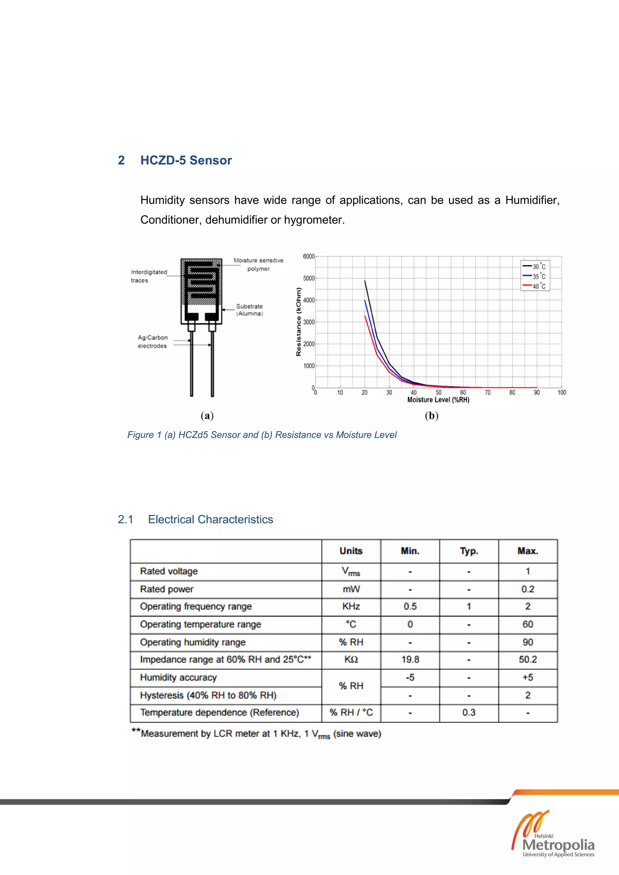
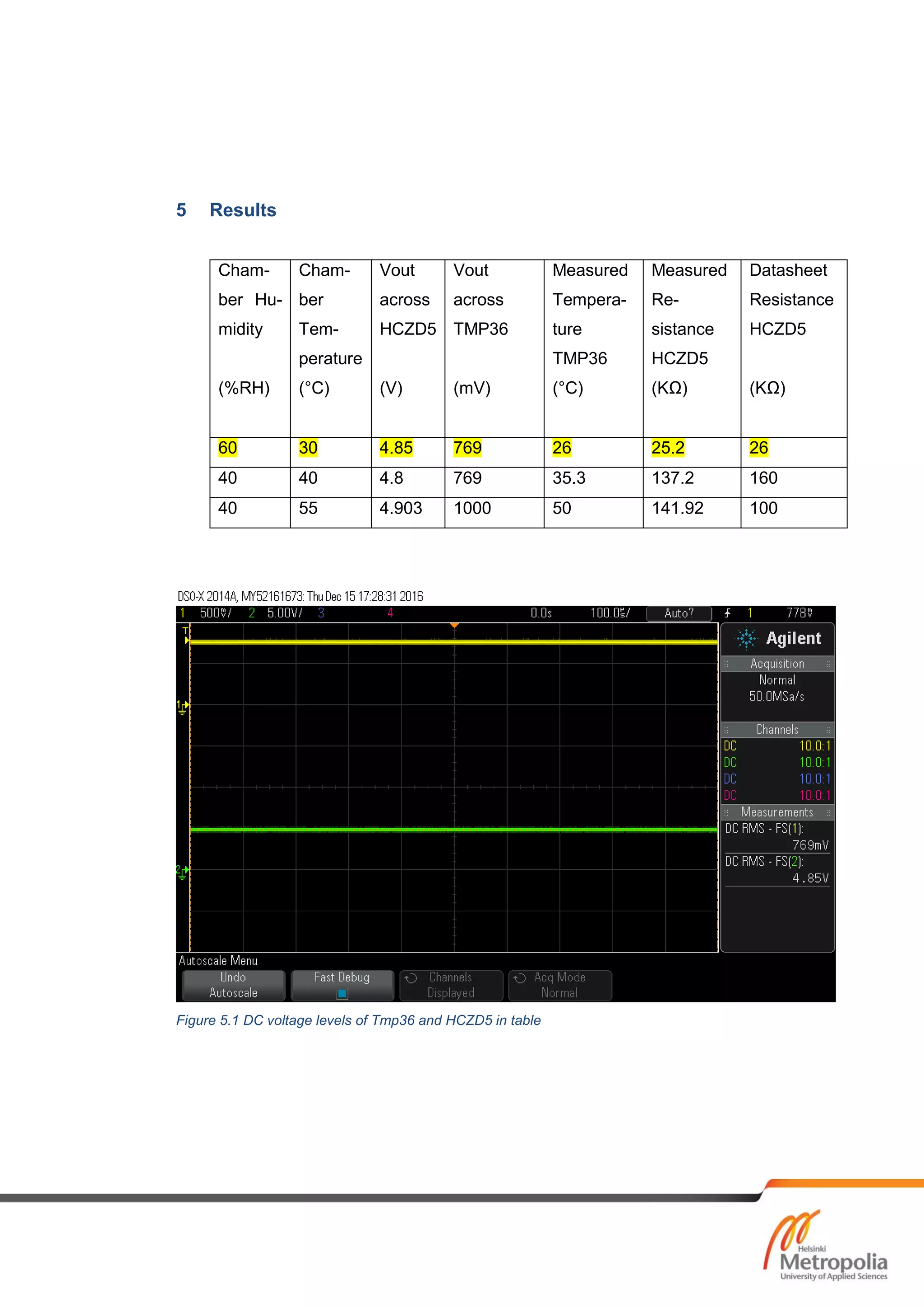
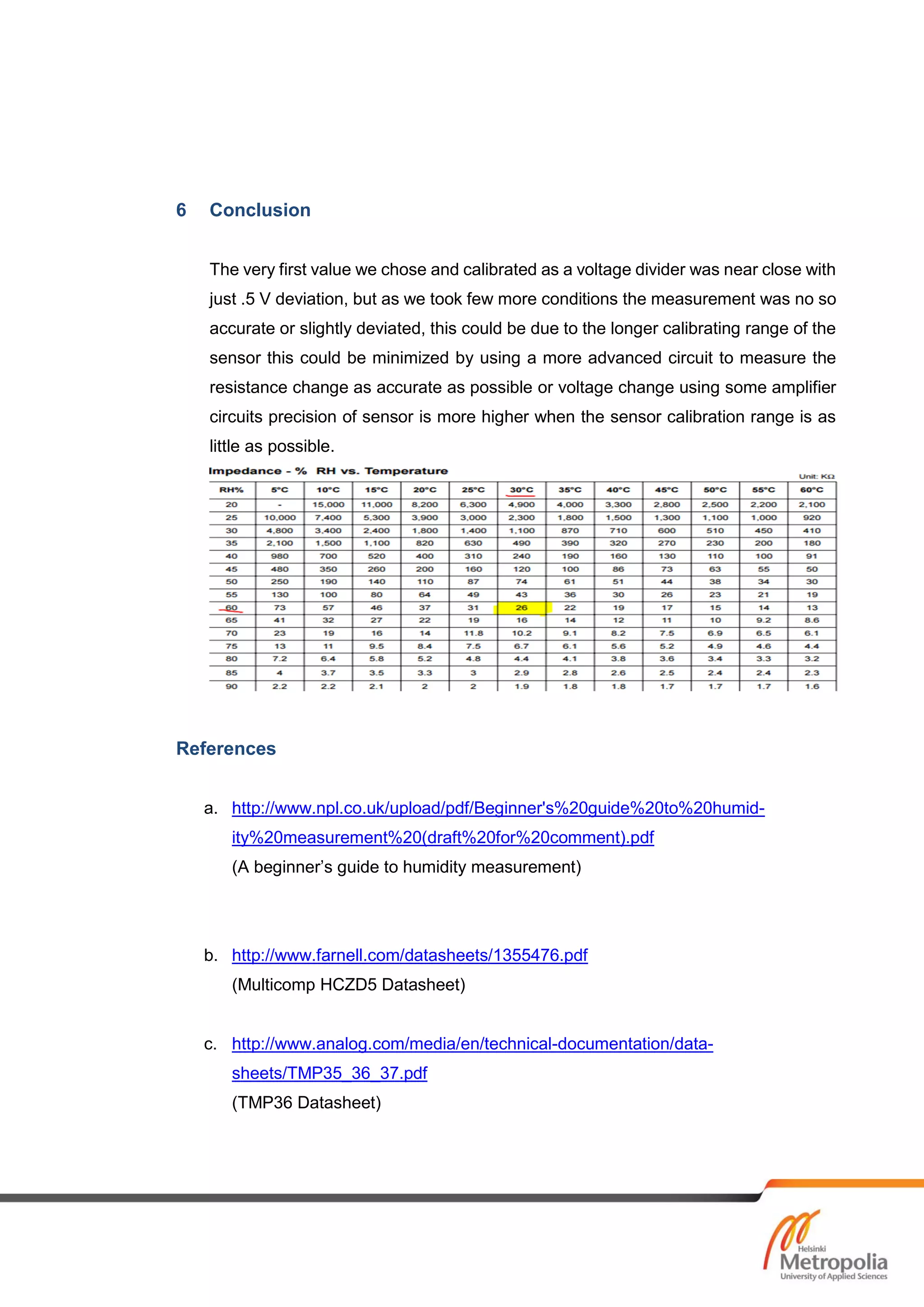

This document summarizes a student project that designed a temperature and humidity sensor using an HCZD-5 humidity sensor and TMP36 temperature sensor. The sensors were tested in an environment chamber by building a voltage divider circuit to measure the sensors' resistance and voltage outputs at different temperature and humidity levels. The results showed the humidity sensor measurements matched the datasheet values closely at one point but deviated more at other points, possibly due to errors from the sensor's long calibration range. The temperature sensor differed from the chamber readings by around 4 degrees Celsius.


