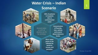
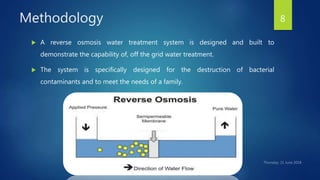
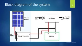
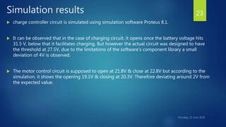
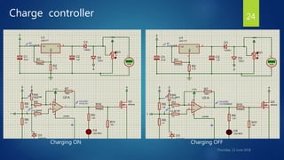
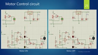
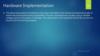
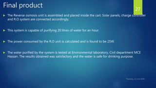
The document discusses the development of a solar-powered portable water purifier aimed at addressing water scarcity and quality issues, particularly in impoverished areas. It outlines the system's design and methodology, including the use of solar panels to power a reverse osmosis purification process. Results indicate that the system can purify 20 liters of water per hour, making it suitable for areas without reliable access to clean water.
![Review of the earlier work
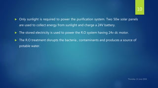
It has become a recent concern and idea to use solar panels as an energy source for
cleaning water in developing countries[1].
The existing water purification systems use UV and RO filters which require electricity
and are powered by utility power supply.
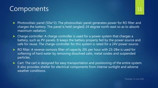
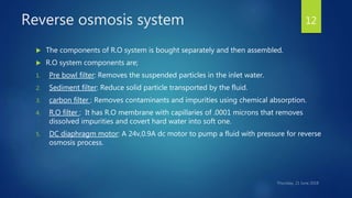
Reverse osmosis is capable of removing up to 99 percent of 65 different contaminants
including lead, fluoride, chlorine, dissolved salts, and much more[3].
Johnathan, Coleman, Jared, Compere, Marc, Fennesy, Kyle students of Embry riddle
Aeronautical University have developed a portable solar water purifier system for public
use during disaster recovery. This system can purify water at the rate of 2-3gpm and
capable of catering the demands of 750-1000 people in a day.
An U. S based company called AID-GEAR has developed a portable, battery powered
water purifier called Oasis-3. The Oasis-3 water purification system is designed to
rapidly provide clean, safe drinking water anywhere in the world.
6](https://image.slidesharecdn.com/finalppt-190120172127/85/Solar-powered-portable-water-Purifier-6-320.jpg)

![References
[1] Jolapara, Kamlesh. "Energize Your Home with Solar Power.“ Futureenergyblog.com.
WordPress, 16 Sept. 2014. Web. Sept. 2014.
[2] Honsberg, Christiana, and Stuart Bowden. "Efficiency and Solar Cell Cost."
PV Education. N.p., Mar. 2013. Web. Apr. 2014.
[3] Warsinger, David M.; Tow, Emily W.; Nayar, Kishor G.; Maswadeh, Laith A.; Lienhard V,
John H. (2016). "Energy efficiency of batch and semi-batch (CCRO) reverse osmosis
desalination". Water Research. pp. 272–282.
[4] Yung Wong, Shavin Pinto, Yan Tang, Marc Compere “Community Development through a
Sustainable Micro-Business Selling Clean Water”, Global Humanitarian Technology
Conference IEEE 2014.
30](https://image.slidesharecdn.com/finalppt-190120172127/85/Solar-powered-portable-water-Purifier-30-320.jpg)