Downloaded 44 times
![Implementation of Solar Inverter for On Grid System
G.H.R.C.E.M, AMRAVATI Page 3
CHAPTER 2
LITERATURE SURVEY
In the research paper “A New Design of Grid Tie Inverter for a Grid
Interactive Solar Photovoltaic Power Generation” author M. Ghoul state that
Photovoltaic systems that convert Solar energy into Electrical Energy are divided into
two main categories: stand-alone (or) off line and grid connected. The first one is
commonly used in rural areas and more often as a back-up system for situations when
the grid isn’t available due to a natural disaster or human caused disruption. Even if
they are capable of providing AC power for immediate appliance usage, most of the
time these systems make use of energy storage devices such as large capacity
batteries, where the energy stored during the day will then be used when sunlight is
not available. On the other hand, grid-connected systems are installed in areas where
the grid is present and robust, and able to accept energy feeding from the above
described photovoltaic systems. Operating a Renewable System in Parallel with an
Electric Grid requires Special Inverters. This Paper Presents the New Design,
Development & Performance Analysis of a Grid Connected PV Inverter. The
experimental results prove that the proposed system can reduce the Energy
Consumption drastically and give a reliable support to the Grid [1].
In the research paper of “Implementation of PV Fed Hybrid Multilevel
Inverter using MPPT” by author D. Manoj Nethala state that versatile stand-alone
photovoltaic (PV) systems still demand on at least one battery inverter with improved
characteristics of robustness and efficiency, which can be achieved using multilevel
topologies. A compilation of the most common topologies of multilevel converters is
presented, and it shows which ones are best suitable among the NPC/ Cascaded H-
Bridge to implement inverters for standalone applications in the range of a few
kilowatts. The harmonic content of the output signals of the both the inverters are
analyzed [2].
In the research paper of “Performance Of The Grid Connected Photovoltaic
System” by author Neeraj and Dwarka Prasad represents the Eco friendly power
generation obtained by sunlight energy through photovoltaic cells. The experimental
model where the energy is fed by traditional means to a 3- phase load has been used.
Efforts have been made to replace the source for load on one of the three phases by a
photovoltaic source. This is going to space the source from feeding 200 KW every](https://image.slidesharecdn.com/implementationofsolarinverter2-170427163408/85/Implementation-of-solar-inverter-2-3-320.jpg)
![Implementation of Solar Inverter for On Grid System
G.H.R.C.E.M, AMRAVATI Page 4
day. A synchronizer has been developed to enable the parallel operation of
photovoltaic cells with the existing A/C power source. This ensures equal voltages
and equal frequencies of both the sources before putting loads.[3]
In research paper of “Simulation and Design of Low Cost Single Phase
Inverter” presented by Nishita Kapadia and Amit Patel represent that how solar
energy is converted into electrical energy in a cost effective manner. The main
components of this solar system are solar cell, DC to DC boost converters, inverter.
Sine wave push pull inverter topology is used for inverter. In this topology only two
MOSFETs are used and isolation requirement between control circuit and power
circuit is also less which helps to decrease the cost of solar inverter. In this paper
design of components for the booster and inverter are done [4].
In a research article of the “Simulation and Analysis of a New Grid Connected
Solar Inverter” by author Mohammad Ahmad, B. H. Khan represents that proposes
and analyzes the performance of a new grid connected inverter topology with Solar
PV (SPV) as a dc source. The simulation is done in SIMULINK/ MATLAB Software.
The RMS inverter output voltage is kept slightly higher than the RMS grid voltage
and the power transfer to the grid is controlled by controlling the phase lag angle of
grid with respect to the inverter. It is shown that when the phase lag angle of the grid
is changed, the THD in output current, RMS current, active power and reactive power
changes while RMS voltage and output voltage THD remains approximately the same
[5].
In the research paper of “On Grid/Grid Tie Solution” presented by J.H.R.E
slin state that a solar grid tied inverter converts DC outputs of PV modules, AC power
suitable for transmission on the power grid, or use it for your own consumptions
often deploying reactive power to meet new grid codes. It must always optimize the
power output via maximum power point tracking and additionally monitoring both the
system.[6]](https://image.slidesharecdn.com/implementationofsolarinverter2-170427163408/85/Implementation-of-solar-inverter-2-4-320.jpg)
![Implementation of Solar Inverter for On Grid System
G.H.R.C.E.M, AMRAVATI Page 5
CHAPTER 3
METHODOLOGY
3.1 Types of Solar system
3.1.1 Grid Connected Solar System
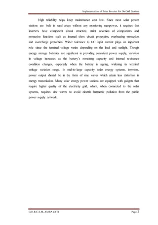
A grid-connected photovoltaic power system or grid-connected PV power
system is an electricity generating solar PV power system that is connected to
the utility grid. A grid-connected PV system consists of solar panels, one or
several inverters, a power conditioning unit and grid connection equipment. They
range from small residential and commercial rooftop systems to large utility-
scale solar power stations. Unlike stand-alone power systems, a grid-connected
system rarely includes an integrated battery solution, as they are still very expensive.
When conditions are right, the grid-connected PV system supplies the excess power,
beyond consumption by the connected load, to the utility grid [1].
Fig 3.1: On Grid System
3.1.2 Working:
Residential grid-connected rooftop systems which have a capacity more than
10 kilowatts can meet the load of most consumers. They can feed excess power to the
grid where it is consumed by other users. The feedback is done through a meter to
monitor power transferred. Photovoltaic wattage may be less than average
consumption, in which case the consumer will continue to purchase grid energy, but a
lesser amount than previously. If photovoltaic wattage substantially exceeds average](https://image.slidesharecdn.com/implementationofsolarinverter2-170427163408/85/Implementation-of-solar-inverter-2-5-320.jpg)
![Implementation of Solar Inverter for On Grid System
G.H.R.C.E.M, AMRAVATI Page 6
consumption, the energy produced by the panels will be much in excess of the
demand. In this case, the excess power can yield revenue by selling it to the grid.
Depending on their agreement with their local grid energy company, the consumer
only needs to pay the cost of electricity consumed less the value of electricity
generated. This will be a negative number if more electricity is generated than
consumed. Additionally, in some cases, cash incentives are paid from the grid
operator to the consumer. Connection of the photovoltaic power system can be done
only through an interconnection agreement between the consumer and the utility
company [1].
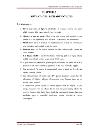
3.1.3 Advantages:
Systems such as Net Metering and Feed-in Tariff which are offered by some
system, operators can offset a customer’s electricity usage costs. In some
locations, though grid technologies cannot cope with distributed generation
feeding into the grid, so the export of surplus electricity is not possible and that
surplus is earthed.
Grid-connected PV systems are comparatively easier to install as they do not
require a battery system.
Grid interconnection of photovoltaic (PV) power generation systems has the
advantage of effective utilization of generating power because there are no storage
losses involved.
A photovoltaic power system is carbon negative over its lifespan, as any energy
produced over and above that to build the panel initially offsets the need for
burning fossil fuels. Even though the sun doesn't always shine, any installation
gives a reasonably predictable average reduction in carbon consumption.](https://image.slidesharecdn.com/implementationofsolarinverter2-170427163408/85/Implementation-of-solar-inverter-2-6-320.jpg)
![Implementation of Solar Inverter for On Grid System
G.H.R.C.E.M, AMRAVATI Page 7
3.1.4 Stand Alone System :
A free standing or Stand Alone PV System is made up of a number of individual
photovoltaic modules (or panels) usually about 12 volts with power outputs of
between 50 and 100+ watts each. These PV modules are then combined into a single
array to give the desired power output. A simple stand alone PV system is an
automatic solar system that produces electrical power to charge banks of batteries
during the day for use at night when the suns energy is unavailable. A stand alone
small scale PV system employs rechargeable batteries to store the electrical energy
supplied by a PV panel or array. Stand alone PV systems are ideal for remote rural
areas and applications where other power sources are either impractical or are
unavailable to provide power for lighting, appliances and other uses. In these cases, it
is more cost effective to install a single stand alone PV system than pay the costs of
having the local electricity company extend their power lines and cables directly to
the home.
A stand alone photovoltaic (PV) system is an electrical system, consisting of an
array of one or more PV modules, conductors, electrical components, and one or more
loads. But a small-scale PV system does not have to be attached to a roof top or
building structures for domestic applications, they can be used for camper vans, RV’s,
boats, tents, camping and any other remote location. Many companies now offer
portable solar kits that allow you to provide your own reliable and free solar
electricity anywhere you go even in hard to reach locations [5].](https://image.slidesharecdn.com/implementationofsolarinverter2-170427163408/85/Implementation-of-solar-inverter-2-7-320.jpg)
![Implementation of Solar Inverter for On Grid System
G.H.R.C.E.M, AMRAVATI Page 13
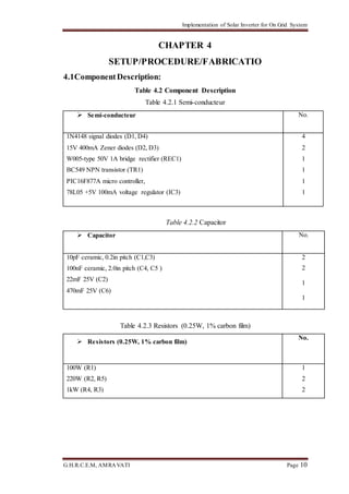
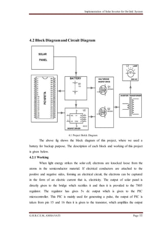
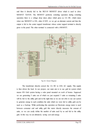
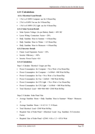
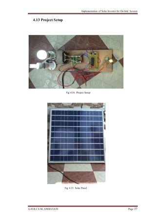
4.3 Hardware Requirement:
Photo Voltaic Cell
MOSFET Driver IR2110
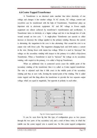
Center Tapped Transformer
MOSFET
PIC16F877A
Regulator 7805
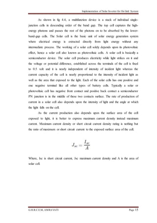
4.4 Photo Voltaic Cell
Photo-voltaic is the direct conversion of light into electricity at the atomic
level. Some materials exhibit a property known as the photoelectric effect that causes
them to absorb photons of light and release electrons. When these free electrons are
captured an electric current results that can be used as electricity [3].
Fig. 4.3: Photovoltaic Cell
The fig 4.3 illustrates the operation of a basic photovoltaic cell, also called a
solar cell. Solar cells are made of the same kinds of semiconductor materials, such as
silicon, used in the microelectronics industry. For solar cells, thin semiconductor,
positive on one side and negative on the other. When light energy strikes the solar
cell, electrons are knocked loose from the atoms in the semiconductor material. If
electrical conductors are attached to the positive and negative sides, forming an
electrical circuit, the electrons can be captured in the form of an electric current that
is, electricity. This electricity can then be used to supply a load, such as a light or a](https://image.slidesharecdn.com/implementationofsolarinverter2-170427163408/85/Implementation-of-solar-inverter-2-13-320.jpg)
![Implementation of Solar Inverter for On Grid System
G.H.R.C.E.M, AMRAVATI Page 14
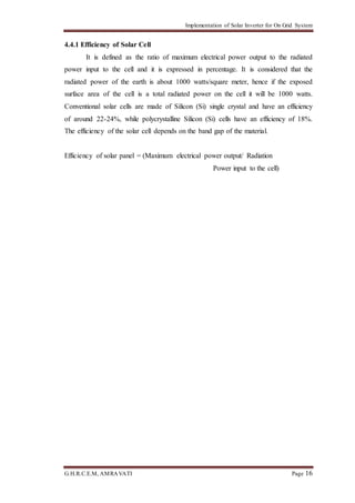
tool. A number of solar cells electrically connected to each other and mounted on a
support structure or frame is called a photovoltaic module. Modules are designed to
supply electricity at a certain voltage, such as a common 12 volt system. The current
produced is directly dependent on how much light strikes the module.
Fig 4.4: Solar Cell Structure
Multiple modules can be wired together to form an array. In general the larger
the area of a module or array, the more electricity that will be produced. Photovoltaic
modules and arrays produce direct-current (dc) electricity. They can be connected in
both series and parallel electrical arrangements to produce any required voltage and
current combination.
Today's most common PV devices use a single junction, or interface, to create
an electric field within a semiconductor such as a PV cell. In a single-junction PV
cell, only photons whose energy is equal to or greater than the band gap of the cell
material can free an electron for an electric circuit. In other words, the photovoltaic
response of single junction cells is limited to the portion of the sun's spectrum whose
energy is above the band gap of the absorbing material, and lower-energy photons are
not used. One way to get around this limitation is to use two (or more) different cells,
with more than one band gap, and more than one junction, to generate a voltage.
These are referred to as "multifunction" cells (also called "cascade" or "tandem"
cells). Multi junction devices can achieve higher total conversion efficiency because
they can convert more of the energy spectrum of light to electricity [3].](https://image.slidesharecdn.com/implementationofsolarinverter2-170427163408/85/Implementation-of-solar-inverter-2-14-320.jpg)
![Implementation of Solar Inverter for On Grid System
G.H.R.C.E.M, AMRAVATI Page 17
4.5 MOSFET Driver IR2110
In many applications, floating circuit is required to drive the high side
MOSFET. In H bridge used in pure sine wave inverter design 2 MOSFET are used as
high side MOSFET and 2 MOSFET are used as low side MOSFET. International
rectifiers IR2110 MOSFET driver can be used as high side and a low side MOSFET
driver. It has a floating circuit to handle to bootstrap operation. IR2210 can withstand
voltage up to 500v (offset voltage). Its output pins can provide peak current up to 2
ampere. It can also be used to as IGBT driver. The IR2210 floating circuit can drive
high side MOSFET up to 500 volt [12].
Fig 4.5: Typical connection of IR2110
Pin 1 is the output of the low side MOSFET drive
Pin2 is a return path for low side. It is at same potential as ground VSS pin
13. Because when input to low side at pin 12 Lin is high, LO output will be
equal to the value of the Vcc voltage at pin 3 with respect to Vss and COM
pin. When the input to lower side at pin 12 Lin is low, LO output will be
equal to the value of VSS and its means zero.
VDD pin 9 is a logic supply pin. Its value should be should be between 5
volts. But if you used voltage less than 4 volts it many not give you required
result.
HIN Pin 10 is an input signal for high side MOSFET driver output. It may be
from a microcontroller or any other device. But the input signal logic level
should be between 4-5 volt.
LIN pin 12 is the input signal for low side MOSFET driver output. It may be
from a microcontroller or any other device. But the input signal logic level
should also be between 4-5 volt.](https://image.slidesharecdn.com/implementationofsolarinverter2-170427163408/85/Implementation-of-solar-inverter-2-17-320.jpg)
![Implementation of Solar Inverter for On Grid System
G.H.R.C.E.M, AMRAVATI Page 22
4.7 MOSFET
The MOSFET (Metal Oxide Semiconductor Field Effect Transistor) transistor
is a semiconductor device which is widely used for switching and amplifying
electronic signals in the electronic devices. The MOSFET is a core of integrated
circuit and it can be designed and fabricated on a single chip because of these very
small sizes. The MOSFET is a four terminal device with source(S), gate (G), drain
(D) and body (B) terminals. The body of the MOSFET is frequently connected to the
source terminal so making it a three terminal device like a field effect transistor. The
MOSFET is very far the most common transistor and can be used in both analog and
digital circuits. The MOSFET works by electronically varying the width of a channel
along which charge carriers flow (electrons or holes). The charge carriers enter the
channel at the source and exit via the drain. The width of the channel is controlled by
the voltage on an electrode is called gate which is located between the source and
drain. It is insulated from the channel near an extremely thin layer of metal oxide. The
MOS capacity present in the device is the main part [9].
Fig 4.8: Construction of MOSFET
4.7.1 Working:
The aim of the MOSTFET is to be able to control the voltage and current flow
between the source and drain. It works almost as a switch. The working of MOSFET
depends upon the MOS capacitor. The MOS capacitor is the main part of the
MOSFET. The semiconductor surface at the below oxide layer which is located
between the source and drain terminals. It can be inverted from p-type to n-type by
applying positive or negative gate voltages respectively. When we apply the positive
gate voltage the holes present under the oxide layer with a repulsive force and holes
are pushed downward with the substrate. The deflection region populated by the
bound negative charges which are associated with the acceptor atoms. The electrons](https://image.slidesharecdn.com/implementationofsolarinverter2-170427163408/85/Implementation-of-solar-inverter-2-22-320.jpg)
![Implementation of Solar Inverter for On Grid System
G.H.R.C.E.M, AMRAVATI Page 23
reach channel is formed. The positive voltage also attracts electrons from the n+
source and drain regions into the channel. Now, if a voltage is applied between the
drain and source, the current flows freely between the source and drain and the gate
voltage controls the electrons in the channel. Instead of positive voltage if we apply
negative voltage, a whole channel will be formed under the oxide layer [9].
Fig 4.9: Working of MOSFET
4.7.2 N- Channel MOSFET:
The N-Channel MOSFET has a N- channel region between source and drain It
is a four terminal device such as gate, drain, source, body. This type of MOSFET the
drain and source is heavily doped n+ region and the substrate or body is P- type. The
current flows due to the negatively charged electrons. When we apply the positive
gate voltage the holes present under the oxide layer pushed downward into the
substrate with a repulsive force. The deflection region is populated by the bound
negative charges which are associated with the acceptor atoms. The electrons reach
channel is formed. The positive voltage also attracts electrons from the n+ source and
drain regions into the channel. Now, if a voltage is applied between the drain and
sources the current flows freely between the source and drain and the gate voltage
controls the electrons in the channel. Instead of positive voltage if we apply negative
voltage a whole channel will be formed under the oxide layer [9].](https://image.slidesharecdn.com/implementationofsolarinverter2-170427163408/85/Implementation-of-solar-inverter-2-23-320.jpg)
![Implementation of Solar Inverter for On Grid System
G.H.R.C.E.M, AMRAVATI Page 25
4.8 PIC16F877A
The PIC16F877A is one of the most renowned microcontroller in the industry.
This controller is very convenient to use, the coding or programming of this controller
is also easier. One of the main advantages is that it can be write-erase as many times
as possible because it uses FLASH memory technology. It has a total number of 40
pins and there are 33 pins for input and output. PIC16F877A is used in many PIC
microcontroller projects. PIC16F877A also have much application in digital
electronics circuits [12].
Fig 4.10: Pin diagram of PIC16F877A
1. PIN1:MCLR
The first pin is the master clear pin of this IC. It resets the microcontroller and
is active low, meaning that it should constantly be given a voltage of 5V and if 0 V
are given then the controller is reset. Resetting the controller will bring it back to the
first line of the program that has been burned into the IC.
2. PIN 2: RA0/AN0
PORT A consists of 6 pins, from pin 2 to pin 7, all of these are bidirectional
input/output pins. Pin 2 is the first pin of this port. This pin can also be used as an
analog pin AN0. It is built in analog to digital converter.](https://image.slidesharecdn.com/implementationofsolarinverter2-170427163408/85/Implementation-of-solar-inverter-2-25-320.jpg)

![Implementation of Solar Inverter for On Grid System
G.H.R.C.E.M, AMRAVATI Page 30
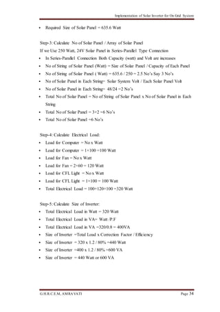
4.9 LM 7805 Regulator
The LM7805 series of three terminal regulators are available with several
fixed output voltages making them useful in a wide range of applications. One of
these is local on card regulation, eliminating the distribution problems associated with
single point regulation. The LM7805 series is available in an aluminum TO-3 package
which will allow over 1.0A load current if adequate heat sinking is provided. Current
limiting is included to limit the peak output current to a safe value. Safe area
protection for the output transistor is provided to limit internal power dissipation. If
internal power dissipation becomes too high for the heat sinking provided, the thermal
shutdown circuit takes over preventing the IC from overheating. Considerable effort
was expanded to make the LM7805 series of regulators easy to use and minimize the
number of external components. It is not necessary to bypass the output, although this
does improve transient response. Input bypassing is needed only if the regulator is
located far from the filter capacitor of the power supply. For output voltage other than
5V, 12V and 15V the LM117 series provides an output voltage range from 1.2V to
57V [9].
4.9.1 Features:
Output current in excess of 1A Internal thermal overload protection
No external components required
Output transistor safe area protection
Internal short circuit current limit
Available in the aluminum TO-3 package
Fig 4.12: LM7805 Regulator](https://image.slidesharecdn.com/implementationofsolarinverter2-170427163408/85/Implementation-of-solar-inverter-2-30-320.jpg)
![Implementation of Solar Inverter for On Grid System
G.H.R.C.E.M, AMRAVATI Page 31
4.10 PWM Technique
Pulse-width modulation (PWM), or pulse-duration modulation (PDM), is a
modulation technique used to encode a message into a pulsing signal. Although this
modulation technique can be used to encode information for transmission, its main
use is to allow the control of the power supplied to electrical devices, especially to
inertial loads such as motors. In addition, PWM is one of the two principal algorithms
used in photovoltaic solar battery chargers, the other being maximum power point
tracking. The average value of the voltage (and current) fed to the load is controlled
by turning the switch between supply and load on and off at a fast rate [8].
The PWM switching frequency has to be much higher than what would affect
the load (the device that uses the power), which is to say that the resultant waveform
perceived by the load must be as smooth as possible. The rate (or frequency) at which
the power supply must switch can vary greatly depending on load and application, for
example Switching has to be done several times a minute in an electric stove; 120 Hz
in a lamp dimmer; between a few kilohertz (kHz), to tens of kHz for a motor drive;
and well into the tens or hundreds of kHz in audio amplifiers and computer power
supplies.
Fig 4.13: Output of PWM](https://image.slidesharecdn.com/implementationofsolarinverter2-170427163408/85/Implementation-of-solar-inverter-2-31-320.jpg)
![Implementation of Solar Inverter for On Grid System
G.H.R.C.E.M, AMRAVATI Page 32
The term duty cycle describes the proportion of 'on' time to the regular interval
or 'period' of time; a low duty cycle corresponds to low power, because the power is
off for most of the time. Duty cycle is expressed in percent, 100% being fully on. The
main advantage of PWM is that power loss in the switching devices is very low.
When a switch is off there is practically no current, and when it is on and power is
being transferred to the load, there is almost no voltage drop across the switch. Power
loss, being the product of voltage and current, is thus in both cases close to zero [8].](https://image.slidesharecdn.com/implementationofsolarinverter2-170427163408/85/Implementation-of-solar-inverter-2-32-320.jpg)
![Implementation of Solar Inverter for On Grid System
G.H.R.C.E.M, AMRAVATI Page 43
CHAPTER 9
REFERENCES
[1]. M.Gohul, T.Jayachandran, Syed Ali, “A New Design Of Grid Tie Inverter
For Grid Interactive Solar System”. IJECT volume2, 3sept 2011.
[2]. D.Manoj Nethala and Vamsi Murli, “Implementation of PV Fed Hybrid
Inverter using MPPT” in ISSN 2319 -8885, Vol 04 Issue 0.3, February-2015,
Pages:0422-0431.
[3]. Neeraj and Dwarka Prasad “Performance Of The Grid Connected Photovoltaic
System” in Volume 3, Issue 1, January 2014 ISSN 2319 – 4847.
[4]. Nishit Kapadia, Amit Patel, Dinesh Kapadia,”Simulation And Design of Low
Cost Single Phase Inverter”, ISSN 2250-2459, Volume 2, Issue 1, February
2012
[5]. M. Ahmed and B.H.Khan, “Simulation and Analysis of a New Grid
Connected Solar Inverter” Sch. J. Eng. Tech., 2014; 2(3A):320-325 ISSN
2347-9523.
[6]. J.H.R.Eslin and H.S.H. Chung, “On Grid/Grid Tie Solution” vol.-16, no.-1,
pp.46-54,January 2001.
[7]. Beser E, Camur S, Arifoglu B, Kandemir Beser E; A grid connected
photovoltaic power conversion system with single phase multilevel inverter.
Solar Energy, 2010; 84(12): 2056-2067
[8]. D.G. Holmes, and P.M. Brendan, “Opportunities for harmonic cancellation
with carrier based PWM for two levels and multilevel cascaded inverters”,
IEEE Trans. on Industry Applications, Vol.37, No.2, pp. 574-582, 2001.
[9]. M D Singh, K B Khanchandani, “POWER ELECTRONICS”, TATA
McGRAW HILL company, Second edition,Chapter9, page no 540- 570.
[10]. G.D.Rai, “Non Conventional Energy Sources”,Khanna Publishers, fifth
edition chapter 4,page no 123-146 and chapter 5, 147-224
[11]. Mueller, O.M.; Mueller, E.K, “Off-grid, low-cost, electrical sun-car system for
developing countries”,Global Humanitarian Technology Conference
(GHTC), 2014 IEEE Year: 2014, Pages: 14 -17
DOI: 10.1109/GHTC.2014.6970254.
[12]. http://ww1.microchip.com/downloads/en/DeviceDoc/39582b.pdf](https://image.slidesharecdn.com/implementationofsolarinverter2-170427163408/85/Implementation-of-solar-inverter-2-43-320.jpg)

The document discusses solar inverters for on-grid solar energy systems. It explains that solar inverters are necessary to convert the direct current (DC) output of solar panels into alternating current (AC) that can be fed into the electric grid. High efficiency and reliability are important for solar inverters in order to optimize the performance and minimize maintenance costs of solar energy systems. The document also provides an overview of grid-connected solar power systems and how excess power from such systems can be supplied to the electric grid or used to offset on-site electricity consumption.


