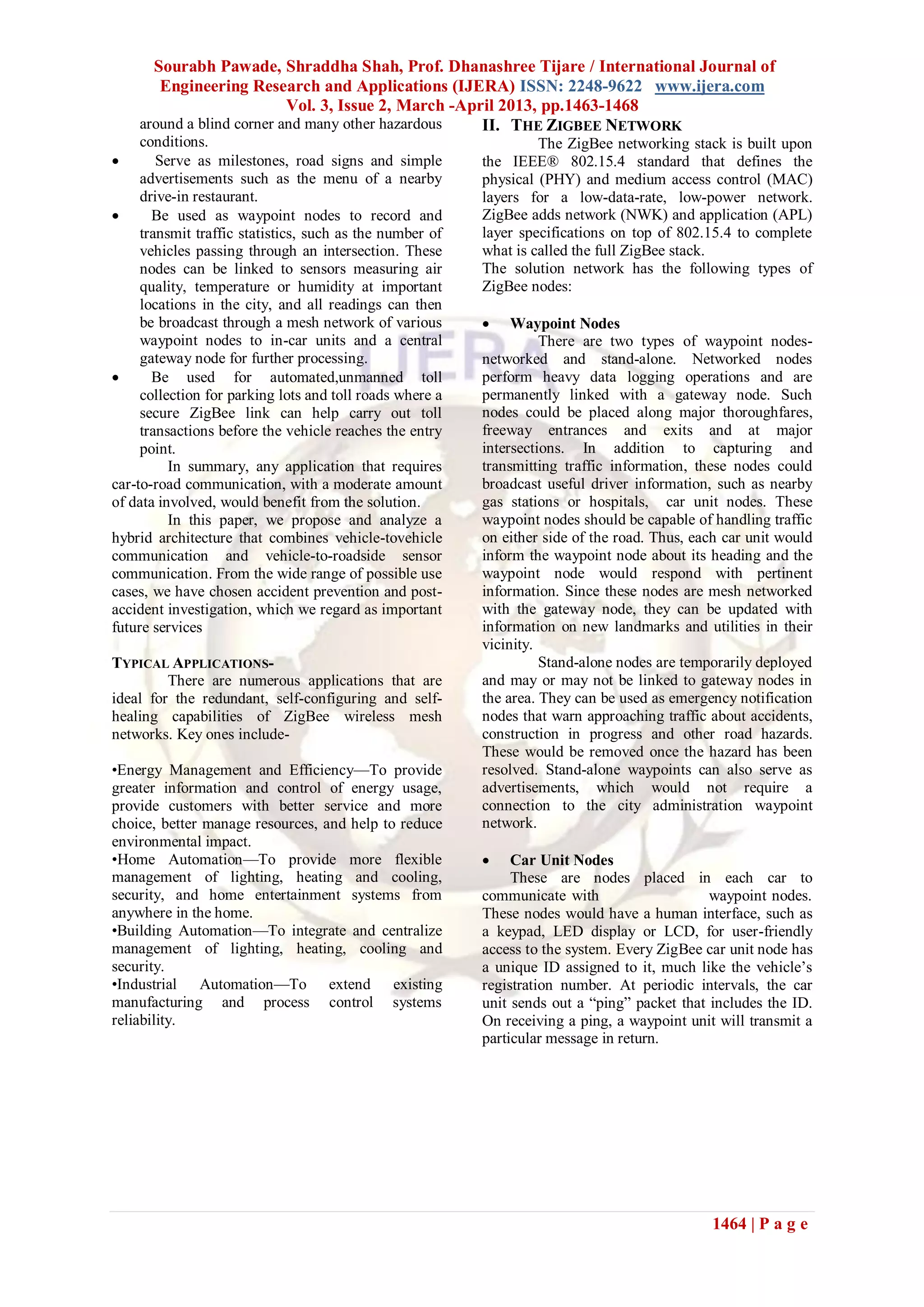
The document presents a Zigbee-based intelligent driver assistance system designed to enhance road safety through low-cost and low-power wireless communication. This system alerts drivers to various road conditions and hazards by integrating vehicle-to-vehicle and vehicle-to-roadside communications, akin to a hybrid architecture. It proposes multiple applications including accident prevention, speed control, and drink driving prevention, emphasizing the scalability and reliability of the Zigbee protocol in automotive contexts.
![Sourabh Pawade, Shraddha Shah, Prof. Dhanashree Tijare / International Journal of
Engineering Research and Applications (IJERA) ISSN: 2248-9622 www.ijera.com
Vol. 3, Issue 2, March -April 2013, pp.1463-1468
1465 | P a g e
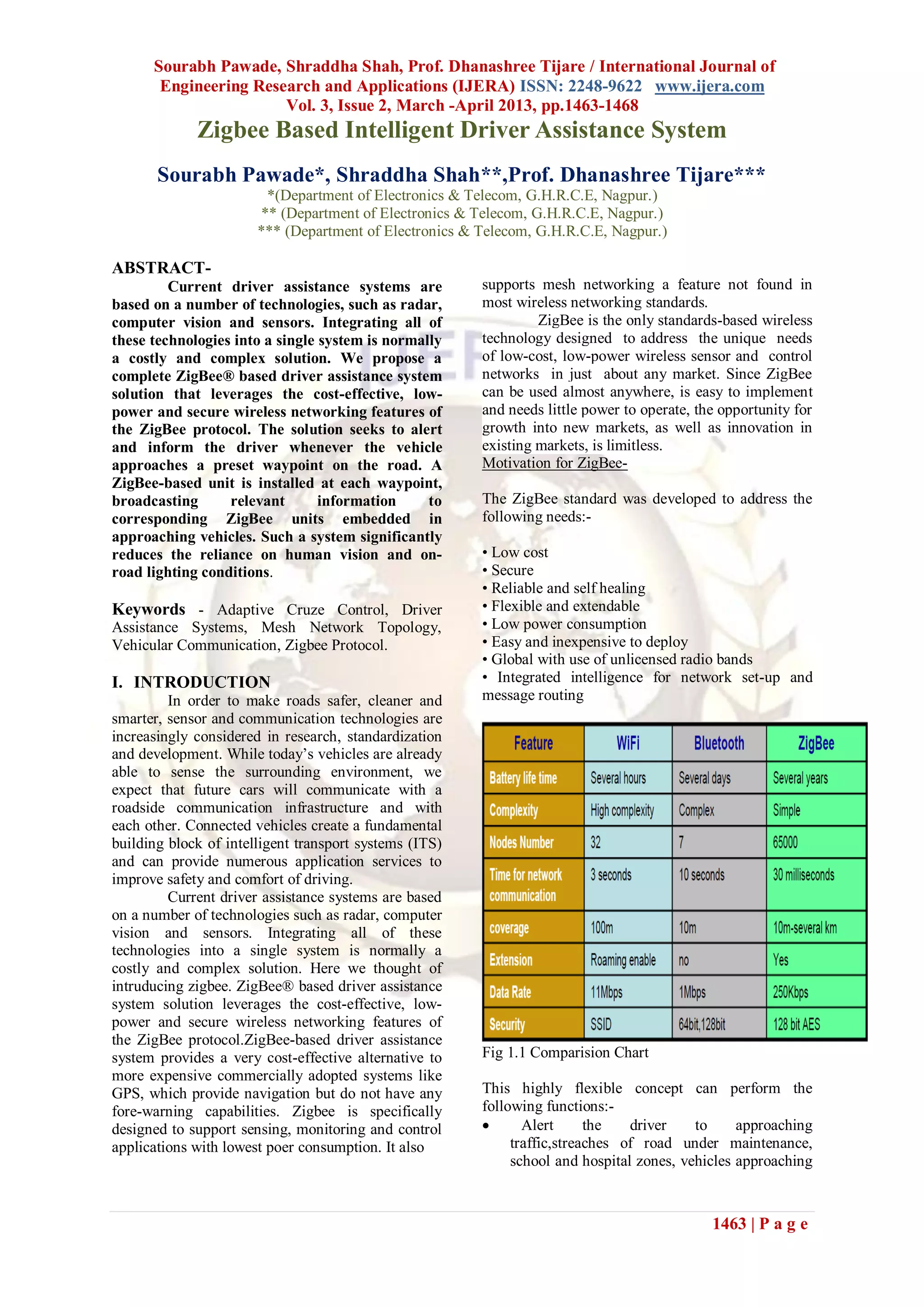
Fig. 2 Methodology
From the above figure it is clear that at
what places the nodes are to be installed. For
example, at node 1 in figure; we can give
information about construction or accident ahead so
that the driver willing to take that route gets an idea
about the road condition before he takes the turn to
choose that route. Sameway we can warn or infrom
the driver with fluel pump ahead, railway crossing
ahead, speed breaker ahead, milestone along with
the specific speed limit of the road.
For all alert scenarios, the placement of the waypoint
units must allow the alert message to be sent out
early enough to give the driver enough time to react.
The correct placement of the unit depends on the
following factors:-
Factor 1: The broadcast range of the waypoint unit
or the car unit (whichever is shorter)
Factor 2: The data rate of the ZigBee link between
the car and the waypoint unit.
Factor 3: The average human reaction time.
Factor 4: The posted speed limit, which helps
determine the average distance it takes for the car to
come to a halt.
Fig 3. Architecture.
III. MESH NETWORK TOPOLOGY
Mesh topology, also called peer-to-peer,
consists of a mesh of interconnected routers and end
devices. Each router is typically connected through
at least two pathways, and can relay messages for its
neighbours.
As shown in the image above, a mesh network
contains a single coordinator, and multiple routers
and end devices.
Mesh topology supports ―multi-hop‖
communications, through which data is passed by
hopping from device to device using the most
reliable communication links and most cost-effective
path until its destination is reached.
The multi-hop ability also helps to provide fault
tolerance, in that if one device fails or experiences
interference, the network can reroute itself using the
remaining devices.
Benefits-
• This topology is highly reliable and robust. Should
any individual router become inaccessible,
alternative routes can be discovered and used.
• The use of intermediary devices in relaying data
means that the range of the network can be
significantly increased, making mesh networks
highly scalable.
• Weak signals and dead zones can be eliminated by
simply adding more routers to the network.
IV. SYSTEM DETAILS
We introduce the terms ―mobile unit‖ and
―static unit‖ here. The ZigBee unit installed in the
vehicle is called the mobile unit, while a waypoint
unit on the road is the static unit. In a mobile unit, an
LCD screen and an array of LEDs on a vehicle’s
dashboard serve to display the messages and alert
the driver along with audio warnings. The kind of
LCD used (segmented or color) depends on the kind
of MCU used and the cost of the unit. If the
MCF1322x Platform in a Package™ (PiP)[1] is
used, then the LCD can be connected via SPI. LEDs
can be applied through GPIOs or RGPIOs and can
be used in a low-cost solution in place of an LCD.
Also, waypoint nodes and gateway nodes do not
require LCDs, as a technician can connect the node
to a laptop to view its information during debug and
maintenance. Audio alerts are a must for all mobile
nodes.
To conserve power, the static unit is in sleep mode
most of the time, waking up when it detects an
approaching vehicle. Solar energy can also be used
to power the waypoint and recharge its batteries for
enhanced 24-hour energy efficiency.](https://image.slidesharecdn.com/ieeeprotechnosolutions-2013ieeeembeddedprojectzigbeebasedintelligentdriverassistancesystem-160128120419/75/Ieeepro-techno-solutions-2013-ieee-embedded-project-zigbee-based-intelligent-driver-assistance-system-3-2048.jpg)
![Sourabh Pawade, Shraddha Shah, Prof. Dhanashree Tijare / International Journal of
Engineering Research and Applications (IJERA) ISSN: 2248-9622 www.ijera.com
Vol. 3, Issue 2, March -April 2013, pp.1463-1468
1467 | P a g e
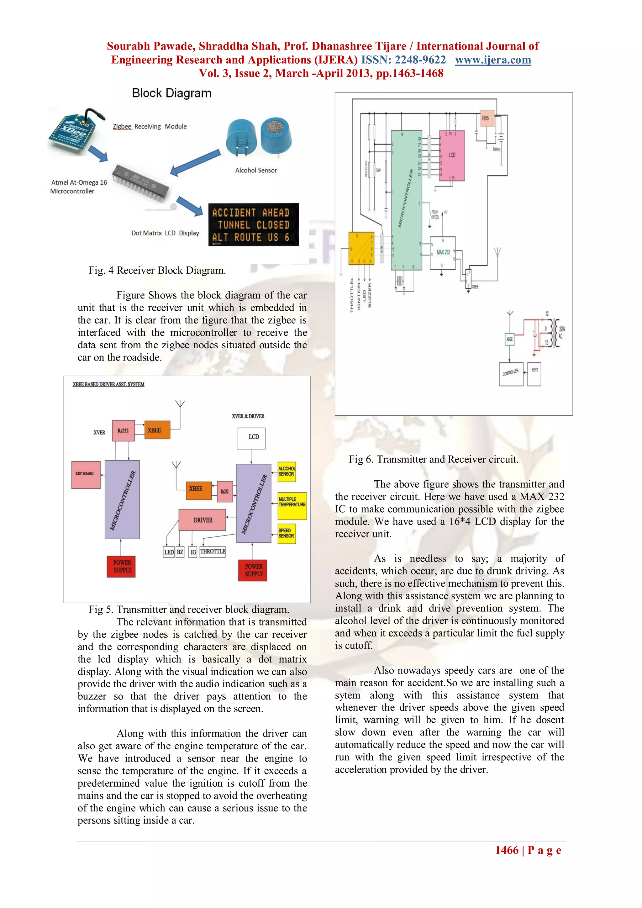
Drink and Drive Prevention System
Fig 7. Flow chart for Drink and Drive Prevention
system.
Drunk driving is a big problem in every
part of the nation. In 2009 alone, over 10,000 traffic
fatalities were linked directly to drivers who had
blood alcohol levels above the legal limit. Alcohol
sensors can help to prevent these accidents. There
are three common alcohol sensing technologies. One
is a sniffer, which detects alcohol in the air or in the
breath of the driver.
Sniffers can detect trace amounts of alcohol
in the air. They can be used to determine if the
person behind the steering wheel is drunk. An
advantage is that sniffer systems do not require skin
contact and can operate at a distance. Sniffers placed
in the vicinity of a driver are capable of measuring
the driver's breath or tissue for alcohol. This
technology is rather small and can be placed into law
enforcement flashlights to determine whether a
driver has alcohol on his or her breath or whether a
drink has alcohol in it. Alcohol can be detected in
the air of a car, even when the windows are half-
down and the air conditioning is on. Systems
employing these sensors can lock a car's ignition if
the driver is too impaired to drive legally.
Speed Control System
It is known that road accidents are
increasing day by day. Most of these road accidents
are caused because the automobiles are driven at
high speeds even in the places where sharp turnings
and junctions exist [1]. Running the automobiles
even at those places is the main cause for the
accidents. Reduction of number of such accidents is
the prime step needed to be taken. Many systems
have been developed to prevent these road accidents.
One of them is Cruise control system (CC) [2] that is
capable of maintaining speed defined by the driver
and its later evolution version Adaptive Cruise
Control (ACC) [3] that keeps the automobile at safer
distance from the preceding vehicle. But these
systems have no capability to detect the
actual speed limit of the road which is required for
safer transportation. So we are proposing a system in
which the zigbee node placed on the roadside
broadcasts the speed limit of the road. The receiver
in the car gets the speed limit and gives the control
to the speed check circuit. If it is found that the car is
over speeding; the speed control is taken by the
controller and the car runs with the specified speed
limit as broadcasted by the zigbee node.
Fig 8. Flow chart of speed control system.
In our proposed design automobile is
always in either Normal mode or Active mode. An
automobile operates in normal mode until wireless
module receives any data packet from the
transmitter.
In Active mode of operation
microcontroller unit continuously studies the speed
of the car. To control the speed of the car according
to the limits we have developed the fuzzy logic. If
the speed of the car is above the Maximum speed
limit, then it sends the digital signal to the ECU such
that speed of the automobile will be decreased.
When the accelerator pedal is moved to increment
the speed, microcontroller calculates the speed that
would be reached on the new pedal position. If the
speed is greater than the maximum speed limit then
it denies excess speed and gives appropriate signal to
the ECU.](https://image.slidesharecdn.com/ieeeprotechnosolutions-2013ieeeembeddedprojectzigbeebasedintelligentdriverassistancesystem-160128120419/75/Ieeepro-techno-solutions-2013-ieee-embedded-project-zigbee-based-intelligent-driver-assistance-system-5-2048.jpg)
![Sourabh Pawade, Shraddha Shah, Prof. Dhanashree Tijare / International Journal of
Engineering Research and Applications (IJERA) ISSN: 2248-9622 www.ijera.com
Vol. 3, Issue 2, March -April 2013, pp.1463-1468
1468 | P a g e
FUTURE SCOPE
For future scope we propose and analyze a
hybrid architecture that combines vehicle-to vehicle
communication and vehicle-to-roadside sensor
communication. From the wide range of possible use
cases, we have chosen accident prevention which we
regard as important future service. For accident
prevention, roadside sensor nodes measure the road
condition at several positions on the surface,
aggregate the measured values and communicate
their aggregated value to an approaching vehicle.
The vehicle generates a warning message and
distributes it to all vehicles in a certain geographical
region.
V. CONCLUSION
In this paper we discussed the importance
of an efficient driver assistance system and how it
can help us improve safety standards on the road.
The solution can significantly reduce the risk to
drivers and enable better traffic management.
Our ZigBee-based driver assistance system
provides a very cost-effective alternative to more
expensive commercially adopted systems like GPS,
which provide navigation but do not have any fore-
warning capabilities..We showcased a number of
ZigBee-enabled application scenarios related to
automotive and road safety, such as data logging,
information broadcasting and driver alerts.
REFERENCES:
[1] Suhas Chakravarty, ―Low-Cost Driver
Assistance Using ZigBee‖,in Beyond Bits-
2009,http://www.freescale.com/files/microc
ontrollers/doc/brochure/LowCostDriverAss
ist.pdf
[2] T. Shyam Ramanath, ―Integrated Drunken
Driving Prevention System‖, In World
Acedamy Of Science-Engineering And
Technology, Aug.04-2010,Pg No-830.
[3] Concept of an Intelligent Adaptive Vehicle
Assistance System, H. Shadeed, J.
Wallaschek; Proceedings of the 2007 IEEE
Intelligent Vehicles Symposium.
[4] Zonal Location and Asset Tracking with
ZigBee Technology (using RSSI),
Cambridge Consultants (Oct. 12, 2006),
www.zigbee.org/imwp/idms/popups/pop_d
ownload.asp?contentID=9567
[5] Research On The Road To Intelligent Cars,
ScienceDaily (Mar. 11, 2006),
www.sciencedaily.com/releases/2006/03/06
0311090833.htm
[6] Ioannou, P.A.; Chien, C.C. Autonomous
Intelligent Cruise Control. IEEE Trans.
Veh. Technol. 1993, 42, 657–672.
[7] http://www.atmel.com/dyn/resources/prod_
documents /doc8154.pdf this document
contains the description ofatmelmega16A
microcontroller.
[8] Lusetti, B.; Nouveliere, L.; Glaser, S.;
Mammar, S.Experimental Strategy for A
System Based Curve Warning System for A
Safe Governed Speed of A Vehicle.
[9] Designing a ZigBee-ready IEEE 802.15.4-
compliant radio transceiver,
http://rfdesign.com/mag/radio_designing_zi
gbeeready_ieee/
[10] M Ozaki, Y. Adachi, Y. Iwahori, and N.
Ishii, Application of fuzzy theory to
writer recognition of Chinese characters,
International Journal of Modelling and
Simulation, 18(2), 1998, 112-116.
Books
[1] R.E. Moore, Interval analysis (Englewood
Cliffs, NJ: Prentice-Hall, 1966).
[2] P.O. Bishop, Neurophysiology of binocular
vision, in J.Houseman (Ed.), Handbook of
physiology, 4 (New York: Springer-Verlag,
1970) 342-366.
Theses:
[3] D.S. Chan, Theory and implementation of
multidimensional discrete systems for
signal processing, doctoral diss.,
Massachusetts Institute of Technology,
Cambridge, MA, 1978.](https://image.slidesharecdn.com/ieeeprotechnosolutions-2013ieeeembeddedprojectzigbeebasedintelligentdriverassistancesystem-160128120419/75/Ieeepro-techno-solutions-2013-ieee-embedded-project-zigbee-based-intelligent-driver-assistance-system-6-2048.jpg)


![ANPARA THERMAL POWER STATION[1] sangam.pdf](https://cdn.slidesharecdn.com/ss_thumbnails/anparathermalpowerstation1sangam-251121115219-9261cde4-thumbnail.jpg?width=640&height=640&fit=bounds)


