Downloaded 19 times

![provide a simple-to-use graphical user interface to them.
The module’s baud rate, channel number,and network ID etc. can be configure by sending the set of AT commands to the XBee Module using the X-CTU software. The Test / Query button is used to test the selected COM port and PC settings. The Host Setup tab allows the user to configure how the X-CTU program is to interface with a radio’s firmware. This includes determining whether API or AT command mode will be used to access the module’s firmware as well as the proper command mode character and sequence.
6. CONCLUSION
With the help of this study, a parameter monitoring system for induction machines based on Zigbee protocol is achieved and tested successfully. The system developed is capable to perform such operations as running the motor though RF, stopping it, measuring, monitoring and controlling the most parameters of the motor like phase currents, phase voltages, wiring temperature, speed. All of these values can be transferred to the host computer, displayed on the interface, represented graphically; Monitoring and controlling the basic parameters of the induction motors were examined and achieved in various ways. A new ZigBee technology is a new wireless protocol is used for the communication. This protocol is widely used various areas for its better reliability, low power consuming profile, excellent Capability, high flexibility and low cost. So it’s significant to embed the ZigBee protocol into the WSN system that widely applied now in every area. The system achieved can be used for industrial applications. The whole system may be very useful to colleges and research institutes that have vocational, technical, and industrial education
REFERENCES
[1] Tanmoy Maity , Partha sarathi Das , and Mithu Mukherjee, “Rescue and protection system for underground mine workers based on Zigbee ” Int. Jr. Of Advanced Computer Engineering & Architecture Vol. 2 No. 2 (June - December,12)
[2]Jui-Yu Cheng and Min-Hsiung Hung, Jen-Wei Chang, “A ZigBee-Based Power Monitoring System with Direct Load Control Capabilities” Proceedings of the 2007 IEEE International Conference on
Figure.5. X-CTU setup
Figure.6. Remote Configuration view on X-CTU software 602](https://image.slidesharecdn.com/zigbeebasedparametermonitoringandcontrollingsystemforinductionmachine-141129122350-conversion-gate02/85/Zigbee-based-parameter-monitoring-and-controlling-system-for-induction-machine-5-320.jpg)
![TuesE04 Networking, Sensing and Control, London, UK, 15-17 April 2007
[3] A Comparative Study of Wireless Protocols: Bluetooth, UWB, ZigBee, and Wi-Fi by Jin-Shyan Lee, Yu-Wei Su, and Chung-Chou Shen, Information & Communications Research Labs, Industrial Technology Research Institute (ITRI)
[4] F.L.Lewis, Wireless Sensor Networks- Chapter 4, Smart environments: Technologies, Protocols, and Applications Journal
[5] Ramazan BAYINDIR, Mehmet ŞEN, “A Parameter Monitoring System for Induction Motors based on zigbee protocol”, Gazi University Journal of Science. GU J Sci 24(4):763-771 (2011)
[6] Zulhani Rasin, Mohd Rizal Abdullah , “Water Quality Monitoring System Using Zigbee Based Wireless Sensor Network”, International Journal of Engineering & Technology IJET Vol: 9 No: 10
[7] Shizhuang Lin1, Jingyu Liu2 and Yanjun Fang,” ZigBee Based Wireless Sensor Networks and Its Applications in Industrial”, International Conference on Automation and Logistics August 18 - 21, 2007, Jinan, China 603](https://image.slidesharecdn.com/zigbeebasedparametermonitoringandcontrollingsystemforinductionmachine-141129122350-conversion-gate02/85/Zigbee-based-parameter-monitoring-and-controlling-system-for-induction-machine-6-320.jpg)

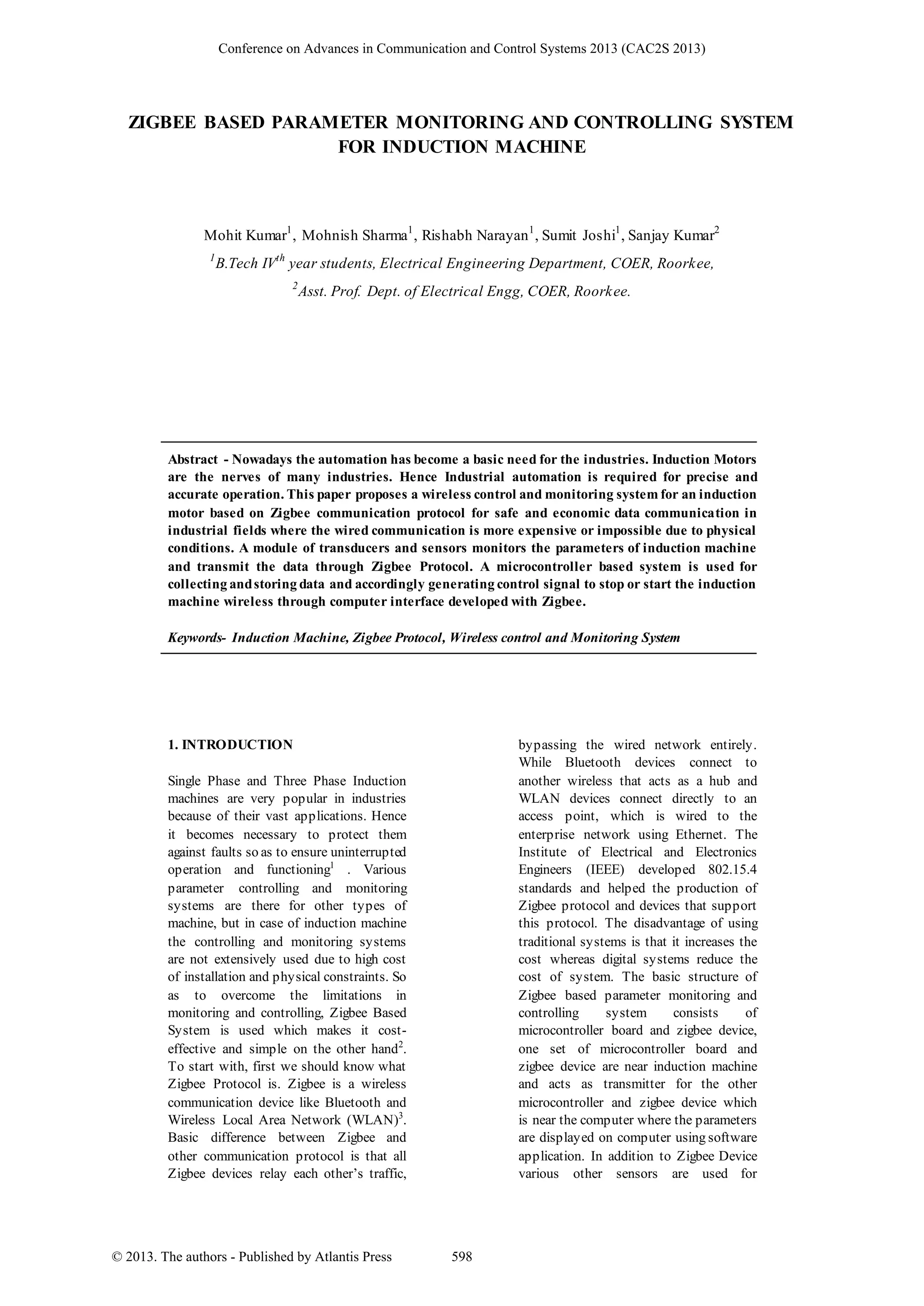
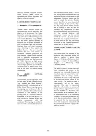
This document summarizes a Zigbee-based system for monitoring and controlling an induction machine. Sensors measure parameters like voltage, current, temperature, and speed. A microcontroller collects the data and transmits it wirelessly via Zigbee protocol. If parameters exceed limits, the microcontroller can stop the machine. A receiver displays data on a computer and allows remote start/stop control of the machine. The system aims to safely and cost-effectively monitor and control induction machines wirelessly.