The document presents a low-cost solution for controlling a DC motor using a Bluetooth module and ARM processor, focusing on energy scavenging through mechanical vibrations. It describes the prototype of a home automation system that integrates MEMS-based energy harvesting to create a self-powered DC motor. Additionally, it highlights the system's efficiency, expandability, and potential for energy conservation by using vibrational energy generated by the motor.
![TELKOMNIKA, Vol.17, No.1, February 2019, pp.481~488
ISSN: 1693-6930, accredited First Grade by Kemenristekdikti, Decree No: 21/E/KPT/2018
DOI: 10.12928/TELKOMNIKA.v17i1.11638 481
Received July 2, 2018; Revised November 13, 2018; Accepted December 12, 2018
Energy scavenging using vibrations from bluetooth
controlled DC motor
Ankita H Harkare
*1
, Sagar Welekar
2
, Abhishek Maheshwari
3
, Suraj Motwani
4
,
Saket Soholkar
5
1
Department of Electronics and Communication Engineering,
Shri Ramdeobaba College of Engineering and Management, Gittikhadan, Katol Road, Nagpur 440013
2,3,4,5
Department of Electronics and Communication Engineering,
Shri Ramdeobaba College of Engineering and Management, Nagpur
*Corresponding author, e-mail: harkareah@rknec.edu
Abstract
Wide spectrum of research for application-based solutions has grown due to the requirement of
automation of general electrical appliances. A low-cost solution is presented in this paper to control DC
motor using Bluetooth module and controlled by an ARM processor. The main objective here is to build an
efficient closed loop system which is wirelessly controlled by ARM processor 2103 using Bluetooth module
and Bluetooth dongle. The system suggested here is expandable and can be integrated with latest
technologies as well. The paper gives the details of the prototype for home automation system and gives
the expected results with 0.1% tolerance. It also suggests the ways to integrate this system with the mobile
phones and hence control the devices with the mobile handsets. The vibration frequency of the DC motor
is used to generate electrical potential using MEMS tecnonlogy. A novel idea of self powered DC motor is
thus presented by installing MEMS based energy harvester on the motor shaft.
Keywords: automation, ARM processor, bluetooth, energy harvester, MEMS, vibrations
Copyright © 2019 Universitas Ahmad Dahlan. All rights reserved.
1. Introduction
Automation has eased human efforts in operating complex as well as simple devices and
thus has become the need of hour. Automation based products have a huge market and thus
consumer requirements are being considered an important part of research as it is reliable and
saves a huge amount of time [1, 2]. Though Bluetooth technology is not a new one, it still
provides a wide range of comfort and usability in varied fields. The control has to be given to the
consumer is what is required and this is easily achieved using the Bluetooth technology. The
usability has also grown to ease the operation for especially abled consumers. It was reported
by the Allied Business Intelligence (ABI) [3] that in 2012 approximately 1.5 million automatic
home appliances were installed in the United States of America (USA) and the rate of increase
in these installations is about 45.2%. However, the controlling of the devices is still the major
concern. Most of the ardiuno based research work is being carried for controlling the
devices/appliances using wireless technologies such as Global System for Mobile (GSM) [4],
General Packet Radio Service (GPRS) [5], ZigBee [6], Z-Wave [7], Infrared [8], wireless fidelity
(Wi-Fi) [9, 10] and Bluetooth [11]; in the process wasting a lot of RAM and CPU cycles. Energy
efficiency needs to be taken care of in today’s scenario as more and more electrical
devices/appliances are being automated: thanks to the ever-evolving technologies. Hence, ARM
based control system has been presented here which uses minimum cycles as per the user
requirements and thus saving energy wastage in the process. Bluetooth has been selected for
wireless communication for low cost solution and ease of installation [12].
Researchers have worked extensilvely in this field to give automated solutions for easy
operation. N. Sriskanthan [13] et al. proposed a remote-controlled module for automation using
Bluetooth through the computer system. A layer built above the bluetooth communication was
suggested for appliances to communicate properly where the controller was connected to
appliances via I2C bus. However, such systems cannot be communicated easily through the
mobile handset and thus needs to be explored further. R. Piyare [14] et al designed wireless
solution for home automation using mobile handsets. However, it works on Symbian OS and](https://image.slidesharecdn.com/5811638-200804022703/85/Energy-scavenging-using-vibrations-from-bluetooth-controlled-DC-motor-1-320.jpg)
![TELKOMNIKA, Vol.17, No.1, February 2019, pp.481~488
ISSN: 1693-6930, accredited First Grade by Kemenristekdikti, Decree No: 21/E/KPT/2018
DOI: 10.12928/TELKOMNIKA.v17i1.11638 481
Received July 2, 2018; Revised November 13, 2018; Accepted December 12, 2018
Energy scavenging using vibrations from bluetooth
controlled DC motor
Ankita H Harkare
*1
, Sagar Welekar
2
, Abhishek Maheshwari
3
, Suraj Motwani
4
,
Saket Soholkar
5
1
Department of Electronics and Communication Engineering,
Shri Ramdeobaba College of Engineering and Management, Gittikhadan, Katol Road, Nagpur 440013
2,3,4,5
Department of Electronics and Communication Engineering,
Shri Ramdeobaba College of Engineering and Management, Nagpur
*Corresponding author, e-mail: harkareah@rknec.edu
Abstract
Wide spectrum of research for application-based solutions has grown due to the requirement of
automation of general electrical appliances. A low-cost solution is presented in this paper to control DC
motor using Bluetooth module and controlled by an ARM processor. The main objective here is to build an
efficient closed loop system which is wirelessly controlled by ARM processor 2103 using Bluetooth module
and Bluetooth dongle. The system suggested here is expandable and can be integrated with latest
technologies as well. The paper gives the details of the prototype for home automation system and gives
the expected results with 0.1% tolerance. It also suggests the ways to integrate this system with the mobile
phones and hence control the devices with the mobile handsets. The vibration frequency of the DC motor
is used to generate electrical potential using MEMS tecnonlogy. A novel idea of self powered DC motor is
thus presented by installing MEMS based energy harvester on the motor shaft.
Keywords: automation, ARM processor, bluetooth, energy harvester, MEMS, vibrations
Copyright © 2019 Universitas Ahmad Dahlan. All rights reserved.
1. Introduction
Automation has eased human efforts in operating complex as well as simple devices and
thus has become the need of hour. Automation based products have a huge market and thus
consumer requirements are being considered an important part of research as it is reliable and
saves a huge amount of time [1, 2]. Though Bluetooth technology is not a new one, it still
provides a wide range of comfort and usability in varied fields. The control has to be given to the
consumer is what is required and this is easily achieved using the Bluetooth technology. The
usability has also grown to ease the operation for especially abled consumers. It was reported
by the Allied Business Intelligence (ABI) [3] that in 2012 approximately 1.5 million automatic
home appliances were installed in the United States of America (USA) and the rate of increase
in these installations is about 45.2%. However, the controlling of the devices is still the major
concern. Most of the ardiuno based research work is being carried for controlling the
devices/appliances using wireless technologies such as Global System for Mobile (GSM) [4],
General Packet Radio Service (GPRS) [5], ZigBee [6], Z-Wave [7], Infrared [8], wireless fidelity
(Wi-Fi) [9, 10] and Bluetooth [11]; in the process wasting a lot of RAM and CPU cycles. Energy
efficiency needs to be taken care of in today’s scenario as more and more electrical
devices/appliances are being automated: thanks to the ever-evolving technologies. Hence, ARM
based control system has been presented here which uses minimum cycles as per the user
requirements and thus saving energy wastage in the process. Bluetooth has been selected for
wireless communication for low cost solution and ease of installation [12].
Researchers have worked extensilvely in this field to give automated solutions for easy
operation. N. Sriskanthan [13] et al. proposed a remote-controlled module for automation using
Bluetooth through the computer system. A layer built above the bluetooth communication was
suggested for appliances to communicate properly where the controller was connected to
appliances via I2C bus. However, such systems cannot be communicated easily through the
mobile handset and thus needs to be explored further. R. Piyare [14] et al designed wireless
solution for home automation using mobile handsets. However, it works on Symbian OS and](https://image.slidesharecdn.com/5811638-200804022703/75/Energy-scavenging-using-vibrations-from-bluetooth-controlled-DC-motor-1-2048.jpg)
![ ISSN: 1693-6930
TELKOMNIKA Vol. 17, No. 1, February 2019: 481-488
482
thus increases the complexity further including the range issues. H. Kanma [15, 16] et al
proposes a Bluetooth Home automation system which is operated by GPRS. Here a mobile
handset with bluetooth operates as host controller where a GSM modem provides the internet
connectivity. The issue is it always requires a strong internet connection for smooth working.
The researchers have given solutions without considering the energy saving and cost
effectiveness [17-19]. Also, the android application-based solutions consume a lot of power and
have not thought regarding the energy efficieny [19-21]. The solution proposed here is modified
and is not only energy efficient but can be extended further using MEMS technology to generate
potential energy as well. This potential energy can be stored using super capacitors to run
various other applications and hence our solution can be energy effivient and self driven.
In the past few years, Micro Electro Mechanical Systems (MEMS) offers potential power
source through mechanical vibrations. Micromachined vibration sensors and energy harvesters
play an important role in present day Microsystems. These Microsystems are also required to
accommodate electronics to harness raw signals into acceptable levels and also to make the
signal insensitive to the effects of signals which are outside the domain of the system.
Frequencies of ambient available vibration source are very low in the order of 40-400 Hz. The
conventional available vibration sensors are PASSIVE i.e. sensors which require external
driving source. This makes it difficult to use it in any applications. Also, minimizing power
consumption, eliminating physical buttons and controls, compensating for gravity and position
are advantages of MEMS based energy harvesters.
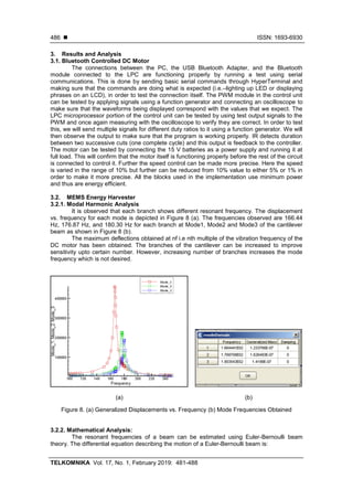
2. Research Method and Proposed Solution
A closed loop controller can be an analog circuit, a digital circuit made of logic gates, or
an ARM Controller. The prototype developed using a simple DC motor to check the feasibility of
the design. Generally, an ARM Controller is the option that will provide more design flexibility. It
aims at performing maily two tasks which involves: i) constantly adjust the average power
delivered to the motor to reach the required speed and ii) Precisely calculate the position/angle
of the motor's output shaft. The algorithm of the design is presented in the form of the flow chart
in Figure 1.
Figure 1. Flow chart describing working of the closed loop sytem](https://image.slidesharecdn.com/5811638-200804022703/85/Energy-scavenging-using-vibrations-from-bluetooth-controlled-DC-motor-2-320.jpg)
![TELKOMNIKA ISSN: 1693-6930
Energy scavenging using vibrations from Bluetooth controlled DC motor (Ankita H Harkare)
483
ARM2103 Controller is one of the most powerful controllers easily available. This
controller features both high-speed, large memory capacity and a host of useful peripheral
features for the most demanding embedded application. All mounted on a very compact board
with easy to connect headers, on-board regulator and direct program download [22-24]. Most
Bluetooth devices, especially those that are used in cell phones, are Class III Bluetooth devices.
The power consumption for a Class III Bluetooth device is approximately 1 mW per
transmission. This makes it a very useful communication method for short range communication
[22]. Here we are using Class A type of bluettoth which has a range upto 100 m sufficient for
controlling a DC Motor from any distance. Figure 1 explains the The PWM module in the control
unit can be tested by applying signals using a function generator and connecting an
oscilloscope to make sure that the waveforms being displayed correspond with the values that
we expect. The LPC microprocessor portion of the control unit can be tested by using test
output signals to the PWM and once again measuring with the oscilloscope to verify they are
correct. Figure 2 shows the block diagram to control the devices wirelessly. We can control
devices such as LED, LCD, relay, DC motor through PC.
Figure 2. Block diagram showing wireless control of devices [22]
Now by pressing different keyboard keys we can operate different devices connected to
different ports of arm processor. For example, when we press ‗B ‘all even numbered LEDs glow
and when we press ‗D ‘all odd numbered LEDs glow. Hence, in this way we can control devices
via PC. Here, after pressing the key the data is transmitted to the module of the kit via dongle
which is inserted in USB port of PC. Now, the module accepts the data and sends it to the arm
processor which transfers this data to respective output ports and also the respective
acknowledgement is sent to the PC [22].
Similarly, the closed loop has been desighed to control the speed of the DC motor. This
is explained in the block diagram of Figure 3. Here we try to maintain constant speed of dc
motor irrespective of load and input supply variations. The count for the speed which is to be
maintained constant is transferred through pc via Bluetooth dongle which is received by
Bluetooth module and is given to arm processor via serial port (UART1). This count is stored in
the arm processor as the “set” value. Initially the motor is rotated at 100% duty cycle to provide
the starting torque. After some rotations the count between two successive cuts which
correspond to one rotation is measured using IR and is compared with the set value. If the count
is less than the set value, then reduce the speed of dc motor which is done by decreasing the
duty cycle and vice-versa. This will maintain the count equal to the “set” value and thus the
speed is maintained constant.
Figure 4 states the cases that have been implemented using speed control of the DC Motor
implementation.
The proposed work where controlling the speed of the dc motor via Bluetooth has been
implemented. The Bluetooth module in arm LPC 2148 is connected to LPC 2103 kit and the
program is burned wirelessly in LPC 2103 IC runs the DC motor at desired duty cycle and also
controls its speed when a load is connected to it.](https://image.slidesharecdn.com/5811638-200804022703/85/Energy-scavenging-using-vibrations-from-bluetooth-controlled-DC-motor-3-320.jpg)
![ ISSN: 1693-6930
TELKOMNIKA Vol. 17, No. 1, February 2019: 481-488
484
These applications eg. DC motor generate certain amount of vibrations which can be
utilized by mounting a MEMS based piezoelectric energy havester on the shaft bearing of the
DC motor. A micro DC motor operating at 12 V produces a maximum speed of 18000 RPM i.e.
around 300 Hz of vibrations. Hence to optimize the same a vibration sensor operating in the
range of
100 to 300 Hz will be required to channelize this vibration energy and convert it into potential
energy. The model suggested by Kumar [25, 26] et al. is apt for this requirement. The structure
can be further extended to generate a wide range of frequencies. The block diagram of this
proposed structure for energy conservation is explained in Figure 5 where the vibration source
is the DC motor. The batch fabrication of this MEMS based energy harvester to be mounted will
reduce the cost of fabrication and the energy reusage will make the appliances self driven and
energy efficient.
Figure 3. Block diagram of speed control of
DC Motor [22]
Figure 4. The cases implemented
for speed control of DC Motor
Figure 5. Proposed structure for energy scavenging
This energy harvester has three cantilever-based arms which operate at different
frequencies. The suggested enrgy harvester can be modified and number of cantilevers can be
increased in parallel configuration in order to increase the range of frequencies. The simulations
are performed in comsol Multiphysics. The energy harvester was designed based on the
piezoelectric effect. The design included a simple cantilever beam with PZT deposition and a
proof mass at its tip.](https://image.slidesharecdn.com/5811638-200804022703/85/Energy-scavenging-using-vibrations-from-bluetooth-controlled-DC-motor-4-320.jpg)

![ ISSN: 1693-6930
TELKOMNIKA Vol. 17, No. 1, February 2019: 481-488
488
supervision and stimulation facilitated to triumph grand altitudes. We express our gratitude
towards him for constant reinforcement and motivation.
References
[1] D. Chowdhry, R. Paranjape, P. Laforge. Smart home automation system for intrusion detection. 2015
IEEE 14
th
Canadian Workshop on Intormation Theory (CWTT). 2015; 75-78.
[2] N. Skeledzija, J.C. Edin, V. Bachler, H. N. Vucemilo, H. Dzapo. Smart home automation system for
energy efficient housing. 37
th
International Convention on Information and Communication Technology
Electronics and Microelectronics (MIPRO). 2014; 166-171.
[3] ABI Research Report 2012.
[4] A. Pramanik, Rishikesh, V. Nagar, S. Dwivedi, B. Choudhury. GSM based Smart home and digital
notice board. 2016 International Conference on Computational Techniques in Information and
Communication Technologies (ICCTICT), 2016; 41-46.
[5] X. Wu, C. Hu, C. Zheng, Q. Zhang. Solar street lamp system using GPRS and ZIGBEE technology.
2016 IEEE 11
th
Conference on Industrial Electronics and Applications (ICIEA). 2016; 2561-2564.
[6] A. R. Al-Ali, M. Qasaimeh, M. Al-Mardini, S. Radder, I. A. Zualkernan. ZigBee-based irrigation system
for home gardens. Communications Signal Processing and their Applications (ICCSPA) 2015
International Conference on. 2015; 1-5.
[7] M. B. Yassein, W. Mardini, A. Khalil. Smart homes automation using Z-wave protocol. 2016
International Conference on Engineering & MIS (ICEMIS) 2016; 1-6.
[8] N. M. Morshed, G. M. Muid-Ur-Rahman, M. R. Karim, H. U. Zaman. Microcontroller based home
automation system using Bluetooth GSM Wi-Fi and DTMF. 2015 International Conference on
Advances in Electrical Engineering (ICAEE) 2015; 101-104.
[9] R. K. Kodali, V. Jain, S. Bose, L. Boppana. IoT based smart security and home automation system.
2016 International Conference on Computing Communication and Automation (ICCCA) 2016;
1286-1289.
[10] M. Asadullah, A. Recai Celik. An Effective Approach to Build Smart Building Based on Internet of
Things (loT). Journal of Basic and Applied ScientificResearch (JBASR). 2016; 6(5): 56-62.
[11] V. Puri, A. Nayyar. Real time smart home automation based on PIC microcontroller Bluetooth and
Android technology. 2016 3
rd
International Conference on Computing for Sustainable Global
Develovment (JNDIACom). 2016; 1478-1484.
[12] S. Palaniappan, N. Hariharan, N. T Kesh, V. S A. Deborah S. Home automation systems-A study.
International Journal of Computer Applications. 2015; 116(11): 11-18.
[13] N. Sriskanthan and Tan Karande. Bluetooth Based Home Automation System. Journal of
Microprocessors and Microsystems. 2002; 26: 281-289.
[14] R. Piyare, M. Tazi. Bluetooth Based Home Automation System Using Cell Phone. 2011 IEEE 15
th
International Symposium on Consumer Electronics. 2011.
[15] H. Kanma, N. Wakabayashi, R. Kanazawa, H. Ito. Home Appliance Control System over Bluetooth
with a Cellular Phone. IEEE Transactions on Consumer Electronics. 2003; 49(4): 1049-1053.
[16] R. Piyare M. Tazil. Bluetooth based home automation system using cell phone. 2011 IEEE 15
th
InternationalSymposium on Consumer Electronics (ISCE). 2011;192-195.
[17] Ramlee Ridza Azri et al. Bluetooth remote home automation system using android application. The
International Journal of Engineering and Science (The IJES). 2013; 2(1): 149-153.
[18] B. Ghazal, K. AI-Khatib. Smart home automation system for elderly and handicapped people using
XBee. International Journal of Smart Home. 2015; 9(4): 203-210.
[19] R. A. Ramlee, M. A. Othman, M. H. Leong, M. M. Ismail, S. S. S. Ranjit. Smart home system using
android application. 2013 International Conference of Information and Communication Technology
(ICoICT). 2013: 277-280.
[20] Rahul Gogawale et al. Bluetooth remote home automation system using android application.
International Engineering Research Journal (IERJ). 2016; 2(2): 848-850.
[21] M. Asadullah, A. Raza. An overview of home automation systems. 2016 2
nd
International Conference
on Robotics and Artificial Intelligence (ICRAI). 2016; 27-31.
[22] Ankita Kumar, Abhishek Maheshwari, Sagar Welekar, Suraj Motwani. Interfacing and Application of
Bluetooth Module using ARM processor. Nagpur, Shri Ramdeobaba Kamla Nehru Engineering
College. 2009.
[23] David Seal. ARM Architecture Reference Manual. Second Edition. Addison-Wesley. 2001. The
definitive reference for the ARM architecture definition.
[24] Steve Furber. ARM System-on-Chip Architecture. Second Edition. Addison-Wesley. 2000. Covers the
hardware aspects of ARM processors and SOC design.
[25] Kumar, Ankita, Balpande SS. Energy Scavenging from Ambient Vibrations Using MEMS Device.
International Journal of Scientific Progress and Research (IJSPR). 2014; 05(-01), ISSN: 2349-4689.
[26] Kumar, Ankita, Balpande SS, Anjankar SC. Electromagnetic Energy Harvester for Low Frequency
Vibrations. Procedia Computer Science. Elsevier. 2016; 79: 785-792.](https://image.slidesharecdn.com/5811638-200804022703/85/Energy-scavenging-using-vibrations-from-bluetooth-controlled-DC-motor-8-320.jpg)