The document presents a novel design for a refreshable braille cell utilizing electrothermal microactuators that harness the hydraulic pressure from the volumetric expansion of melted paraffin wax contained within silicon containers. The braille cell, fabricated through bulk micromachining, aims to create a compact and efficient tactile display for blind and partially sighted users, addressing the limitations of conventional piezoelectric braille displays. Key innovations include specific thermal management techniques and the use of microheaters to control dot height, ensuring reliable and responsive tactile feedback.
![JOURNAL OF MICROELECTROMECHANICAL SYSTEMS, VOL. 14, NO. 4, AUGUST 2005 673
A Micromachined Refreshable Braille Cell
Jun Su Lee and Stepan Lucyszyn, Senior Member, IEEE
Abstract—A new concept for the realization of a refreshable
Braille cell is presented. An electrothermally controlled microac-
tuator that exploits the hydraulic pressure due to the volumetric
expansion of melted paraffin wax is described. The paraffin
wax is contained within a bulk micromachined silicon container.
The container is sealed using an elastic diaphragm of silicone
rubber. The container is heated using gold microheaters located
on an underlying glass substrate. All the layers used to make
up the containers are bonded together using an overglaze paste.
The complete 3 2 dot Braille cell has air gaps between con-
tainers, to prevent unwanted actuation by means of heat leakage
from adjacent containers. The prototype Braille cell measures
7 8.5 2 mm3 and its raised dots are held in equilibrium by
pulsed actuation voltages. To maintain a dot height at 50% of
its maximum, a duty factor of more than 0.8 was found, with an
average power of 0.30 W (PRF = 0 027 Hz). The total actuation
time for a dot on an up/down cycle was 50 s. The dot height
increases with an increasing duty factor with a fixed PRF, and
increases with decreasing PRF with a fixed duty factor. A stable
maximum dot height was achieved by reducing the cooling time.
[1381]
Index Terms—Bulk micromachining, electrothermal microactu-
ators, paraffin wax, refreshable Braille display.
I. INTRODUCTION
ATACTILE display provides information to a user by
stimulating their sense of touch. This information could
be presented using characters, symbols, signals, or physical
forces (e.g., pressure and electrical stimulation). In the field of
tactile technology, research has been conducted into devices
for disabled people and medical instruments of teletaction for
teleoperation (i.e., remote surgery). Refreshable Braille displays
contain tactile devices for the blind and partially sighted,
translating text from a computers into readable characters. A
Braille display consists of a number of Braille cells, with each
containing either six or eight dots arrayed in two columns.
Conventional refreshable Braille cells employ metal pins that
are independently raised. Today, demand for refreshable Braille
displays is increasing, among those within the blind and partially
sighted community that wishes to access modern information
systems.
Since the mid-1970s, piezoelectric and magnetic technolo-
gies have been developed as commercial pin actuators for
refreshable Braille displays; the piezoelectric actuator being
the most common in most displays [1], since the complica-
tions associated with magnetic actuators are avoided. Large
piezoelectric bimorph bars are needed under the pins. The
Manuscript received July 14, 2004; revised October 27, 2004. Subject Editor
G. B. Hocker.
The authors are with the Optical and Semiconductor Devices Group, De-
partment of Electrical and Electronic Engineering, Imperial College London,
London, SW7 2AZ, U.K. (e-mail: jun-su.lee@imperial.ac.uk).
Digital Object Identifier 10.1109/JMEMS.2005.845415
bars push the pins as high as the displacement of their piezo-
electric deformation, by means of an applied electric field.
A typical piezoelectric Braille cell has eight dots (pins) and
eight piezobimorph bars [2], as shown in Fig. 1(a). In prac-
tice, commercial piezoelectric Braille displays consist of only
a single line of 40 or 80 cells, because of the high cost and
large volume of the individual cells. For this reason, a full-page
Braille display is not easy to realize and not affordable using
existing commercial technology.
In recent years, alternative Braille cell actuation technologies
have been investigated. With basic actuators, tactile devices
have been driven using the mechanical movement of pins [3],
electromagnetic [4] and pneumatic forces [5]. Actuators can
also exploit unique material properties, such as shape memory
alloys (SMA) and electrorheological (ER) fluids or gels. As
SMAs can generate considerably large forces, they have been
widely investigated as a method of actuation. An array of
sixty-four tactile elements was connected with SMA (NiTi
alloy) wires [6]. Tactile devices using ER fluids [7] and gels [8]
exploit the property of changing their viscosity to stiffen when
a high electric field (3 to 4 kV/mm) is applied.
Pneumatic and thermopneumatic actuation, using air or gas
pressure, are favorable alternative methods for a refreshable
Braille display because the structure and operation of these
actuators is relatively simple. To create and control Braille
dots, compressed air and active valves are required for these
pneumatic devices. In recent years, with bulk micromachining
technology, electrostatic microvalves are fabricated for pneu-
matic tactile displays [9], [10]. In addition, thermopneumatic
actuators using phase change materials (PCMs, especially
those changing from liquid to gas) have been investigated. Due
to its high vapor pressure, acetone can be used as a suitable
PCM in a thermopneumatic actuator [11]. Although various
actuation methods have been investigated, in relation to Braille
displays, these technologies may have significant obstacles for
the manufacture of full-page Braille displays.
As an alternative PCM, paraffin wax can be used. When
paraffin wax melts, a volumetric expansion of % occurs.
Since the paraffin wax can produce a very large hydraulic
force under expansion, the application of this hydraulic force
has been investigated for applications in macroactuators and
microactuators. Indeed, the Starsys Research Corporation has
developed a linear micropositioning paraffin wax actuator [12],
[13]. For medical applications, a paraffin wax microactuator for
the manipulation of surgical instruments, within an endoscope,
can give pressures of more than 20 MPa [14]. In recent years,
micromachined paraffin wax microactuators [15]–[18] and
paraffin-actuated microvalves [19], [20] have also been studied.
This paper describes a new application of a paraffin wax mi-
croactuator to realize a very thin and compact Braille cells for re-
freshable full-page Braille displays. The Braille cell, composed
1057-7157/$20.00 © 2005 IEEE](https://image.slidesharecdn.com/ieeeprotechnosolutions-ieeeembeddedprojectamicromachinedrefreshablebraillecell-160128120658/85/Ieeepro-techno-solutions-ieee-embedded-project-a-micromachined-refreshable-braille-cell-1-320.jpg)
![JOURNAL OF MICROELECTROMECHANICAL SYSTEMS, VOL. 14, NO. 4, AUGUST 2005 673
A Micromachined Refreshable Braille Cell
Jun Su Lee and Stepan Lucyszyn, Senior Member, IEEE
Abstract—A new concept for the realization of a refreshable
Braille cell is presented. An electrothermally controlled microac-
tuator that exploits the hydraulic pressure due to the volumetric
expansion of melted paraffin wax is described. The paraffin
wax is contained within a bulk micromachined silicon container.
The container is sealed using an elastic diaphragm of silicone
rubber. The container is heated using gold microheaters located
on an underlying glass substrate. All the layers used to make
up the containers are bonded together using an overglaze paste.
The complete 3 2 dot Braille cell has air gaps between con-
tainers, to prevent unwanted actuation by means of heat leakage
from adjacent containers. The prototype Braille cell measures
7 8.5 2 mm3 and its raised dots are held in equilibrium by
pulsed actuation voltages. To maintain a dot height at 50% of
its maximum, a duty factor of more than 0.8 was found, with an
average power of 0.30 W (PRF = 0 027 Hz). The total actuation
time for a dot on an up/down cycle was 50 s. The dot height
increases with an increasing duty factor with a fixed PRF, and
increases with decreasing PRF with a fixed duty factor. A stable
maximum dot height was achieved by reducing the cooling time.
[1381]
Index Terms—Bulk micromachining, electrothermal microactu-
ators, paraffin wax, refreshable Braille display.
I. INTRODUCTION
ATACTILE display provides information to a user by
stimulating their sense of touch. This information could
be presented using characters, symbols, signals, or physical
forces (e.g., pressure and electrical stimulation). In the field of
tactile technology, research has been conducted into devices
for disabled people and medical instruments of teletaction for
teleoperation (i.e., remote surgery). Refreshable Braille displays
contain tactile devices for the blind and partially sighted,
translating text from a computers into readable characters. A
Braille display consists of a number of Braille cells, with each
containing either six or eight dots arrayed in two columns.
Conventional refreshable Braille cells employ metal pins that
are independently raised. Today, demand for refreshable Braille
displays is increasing, among those within the blind and partially
sighted community that wishes to access modern information
systems.
Since the mid-1970s, piezoelectric and magnetic technolo-
gies have been developed as commercial pin actuators for
refreshable Braille displays; the piezoelectric actuator being
the most common in most displays [1], since the complica-
tions associated with magnetic actuators are avoided. Large
piezoelectric bimorph bars are needed under the pins. The
Manuscript received July 14, 2004; revised October 27, 2004. Subject Editor
G. B. Hocker.
The authors are with the Optical and Semiconductor Devices Group, De-
partment of Electrical and Electronic Engineering, Imperial College London,
London, SW7 2AZ, U.K. (e-mail: jun-su.lee@imperial.ac.uk).
Digital Object Identifier 10.1109/JMEMS.2005.845415
bars push the pins as high as the displacement of their piezo-
electric deformation, by means of an applied electric field.
A typical piezoelectric Braille cell has eight dots (pins) and
eight piezobimorph bars [2], as shown in Fig. 1(a). In prac-
tice, commercial piezoelectric Braille displays consist of only
a single line of 40 or 80 cells, because of the high cost and
large volume of the individual cells. For this reason, a full-page
Braille display is not easy to realize and not affordable using
existing commercial technology.
In recent years, alternative Braille cell actuation technologies
have been investigated. With basic actuators, tactile devices
have been driven using the mechanical movement of pins [3],
electromagnetic [4] and pneumatic forces [5]. Actuators can
also exploit unique material properties, such as shape memory
alloys (SMA) and electrorheological (ER) fluids or gels. As
SMAs can generate considerably large forces, they have been
widely investigated as a method of actuation. An array of
sixty-four tactile elements was connected with SMA (NiTi
alloy) wires [6]. Tactile devices using ER fluids [7] and gels [8]
exploit the property of changing their viscosity to stiffen when
a high electric field (3 to 4 kV/mm) is applied.
Pneumatic and thermopneumatic actuation, using air or gas
pressure, are favorable alternative methods for a refreshable
Braille display because the structure and operation of these
actuators is relatively simple. To create and control Braille
dots, compressed air and active valves are required for these
pneumatic devices. In recent years, with bulk micromachining
technology, electrostatic microvalves are fabricated for pneu-
matic tactile displays [9], [10]. In addition, thermopneumatic
actuators using phase change materials (PCMs, especially
those changing from liquid to gas) have been investigated. Due
to its high vapor pressure, acetone can be used as a suitable
PCM in a thermopneumatic actuator [11]. Although various
actuation methods have been investigated, in relation to Braille
displays, these technologies may have significant obstacles for
the manufacture of full-page Braille displays.
As an alternative PCM, paraffin wax can be used. When
paraffin wax melts, a volumetric expansion of % occurs.
Since the paraffin wax can produce a very large hydraulic
force under expansion, the application of this hydraulic force
has been investigated for applications in macroactuators and
microactuators. Indeed, the Starsys Research Corporation has
developed a linear micropositioning paraffin wax actuator [12],
[13]. For medical applications, a paraffin wax microactuator for
the manipulation of surgical instruments, within an endoscope,
can give pressures of more than 20 MPa [14]. In recent years,
micromachined paraffin wax microactuators [15]–[18] and
paraffin-actuated microvalves [19], [20] have also been studied.
This paper describes a new application of a paraffin wax mi-
croactuator to realize a very thin and compact Braille cells for re-
freshable full-page Braille displays. The Braille cell, composed
1057-7157/$20.00 © 2005 IEEE](https://image.slidesharecdn.com/ieeeprotechnosolutions-ieeeembeddedprojectamicromachinedrefreshablebraillecell-160128120658/75/Ieeepro-techno-solutions-ieee-embedded-project-a-micromachined-refreshable-braille-cell-1-2048.jpg)
![674 JOURNAL OF MICROELECTROMECHANICAL SYSTEMS, VOL. 14, NO. 4, AUGUST 2005
Fig. 1. Braille cell technology comparison: (a) commercial piezoelectric actuator for an eight dot cell [2] and (b) proposed concept using an electrothermal
actuator for a six dot cell.
of six dots is fabricated by means of bulk micromachining and
novel bonding techniques. A full-page refreshable Braille dis-
play may be realized by tiling these Braille cells, as illustrated
in Fig. 1(a). This paper discusses the physical and thermal prop-
erties of paraffin wax as a stable hydraulic material, outlines the
novel fabrication processes for realize individual Braille dots
and a complete Braille cells. Finally, the control of the dot height
under dc and pulsed voltage conditions is investigated.
II. CHARACTERISTICS OF PARAFFIN WAX
PCMs are substances that change their phase, from solid to
liquid or from liquid to gas, by means of the variation of ex-
ternal conditions such as temperature or pressure. In general,
during phase changes, their volume also expands or shrinks.
The hydraulic force from the volumetric variation may be ex-
ploited to realize microactuators. Normally, when a crystalline
material melts to a liquid its volume is expanded by phase trans-
formation, since a crystal structure of close-packed atoms or
molecules becomes a liquid state of slack amorphous atomic
structure after melting. Therefore, the volume of the material
increases, because the distance between its atoms increases.
In order to use a suitable PCM as a microactuator for a Braille
cell, the following conditions would be desirable: i) large vol-
umetric change when the phase transforms; ii) reversible reac-
tion on melting (expansion) and solidification (shrinkage); and
iii) sensitive response to the small variation of excitation condi-
tions. From these criteria, paraffin wax is a reasonably suitable
PCM for this purpose.
Paraffinic hydrocarbons are straight-chain or branch-sat-
urated organic compounds with the composition .
The paraffin wax can give a mixture of various hydrocarbon
groups, especially paraffins and cycloalkanes, which are solid
at ambient temperature [21]. When paraffin wax melts, a
volumetric expansion of % occurs over a very narrow
temperature range, around its melting point, as illustrated in
Fig. 2(a). Upon cooling, the same level of shrinkage occurs.
The volumetric expansion during melting generates very large
hydraulic pressures. This pressure has been exploited as an
actuation mechanism for the Braille dots in this research.
The melting point of paraffin wax increases according to
the number of carbon atoms in its composition (i.e., in-
creasing molecular weight). Thus, a paraffin wax can be chosen
with a certain melting point suitable for this application. For
the present research, Fluka 76228 (having a melting point of
Fig. 2. Characteristics of paraffin wax: (a) typical volumetric expansion curve
and (b) measured DSC analysis for Fluka 76 228.
44–46 C) was chosen. The melting and solidifying points were
measured using a TA Instruments 2200 thermal analyzer, fitted
with a 2010 differential scanning calorimeter (DSC), under
high purity Ar (up to 373 K) with a heating rate of 1 K/min.
The result of the measurements showed that actual melting
of the paraffin wax commences at 38.0 C, as illustrated in
Fig. 2(b), and ended at 47.5 C. Thus, the actual melting of the
paraffin wax occurred within a temperature range of C. A
solid-state transition in the crystalline structures, from -phase
to -phase, occurs below the melting point of the paraffin
wax. The - and -phases represent two different crystalline](https://image.slidesharecdn.com/ieeeprotechnosolutions-ieeeembeddedprojectamicromachinedrefreshablebraillecell-160128120658/85/Ieeepro-techno-solutions-ieee-embedded-project-a-micromachined-refreshable-braille-cell-2-320.jpg)
![LEE AND LUCYSZYN: A MICROMACHINED REFRESHABLE BRAILLE CELL 675
Fig. 3. Micromachined Braille cell design: (a) exploded view, (b) illustrated dimensions for International Building Standards, and (c) structure of a paraffin wax
container.
structures within the solid-state paraffin wax. The transition is
accompanied by a release of heat. However, the heat released
was not detected using this DSC analysis. The reason is that the
paraffin wax is not pure but a mixture of several paraffin waxes
that have different melting points. On cooling, solidification
of the molten paraffin wax starts at a temperature of 45 C,
indicating that the rate of cooling is more rapid than the rate of
heating.
III. DESIGN OF THE BRAILLE CELLS
The basic concept in the design of the novel Braille cell is that
paraffin wax fills silicon micromachined containers, which have
integrated microheaters on a bottom glass substrate; the top of
the containers are sealed using elastomer diaphragms of silicone
rubber, as illustrated in Fig. 3(a). In this paper, the dimensions
for the Braille cells were based on the International Building
Standard, given in Table I. This table shows various standard
dimensions for Braille cells. The dot heights vary from a min-
imum of 0.25 mm to a maximum of 1.0 mm.
A. Design of Paraffin Wax Containers
The International Building Standard for Braille dot height
is 0.6 mm, with a bottom diameter of 1.5 mm, as illustrated in
TABLE I
VARIOUS BRAILLE CELL DIMENSIONS [22]
Fig. 3(b). In order to determine the required volume of paraffin
wax to fill the container, the volume within an activated dot was
first calculated using the dome dimension given in Fig. 3(b). The
volume of an activated dome shape dot can be calculated using
the following volume integral:
(1)
where is a spherical radius. The activated dot is part of a
complete hemisphere on the - axis, as shown in Fig. 3(b).](https://image.slidesharecdn.com/ieeeprotechnosolutions-ieeeembeddedprojectamicromachinedrefreshablebraillecell-160128120658/85/Ieeepro-techno-solutions-ieee-embedded-project-a-micromachined-refreshable-braille-cell-3-320.jpg)
![676 JOURNAL OF MICROELECTROMECHANICAL SYSTEMS, VOL. 14, NO. 4, AUGUST 2005
The limits of the integral, and , are shown as points on the
axis. From the dome dimensions, mm and
mm. Using (1), the volume of an activated dot
is, therefore, 0.644 mm . Assuming the volumetric expansion
for the melted paraffin wax is 15 vol. %, the calculated volume
within a raised dot is 15% of the volume of the paraffin wax
within the container before melting. Therefore, the volume of
paraffin wax inside the container is approximately 4.29 mm ,
which is also the volume of a container. Considering the In-
ternational Building Standard dimension for a complete Braille
cell, the structure chosen for the container is a boot shape, as
illustrated in Fig. 3(c). The boot shape container can reduce the
overall thickness of the Braille cell, compared with a cylindrical
column shape. Furthermore, efficient heat delivery to paraffin
wax is possible due to the wide surface area on the bottom sub-
strate. The containers are fabricated using three 525 m thick
silicon wafers, which have been bulk micromachined to realize
the holes needed to construct the containers.
B. Microheaters
Gold microheaters were located on the bottom of the con-
tainers to heat the paraffin wax. The microheaters generate
enough thermal energy, through Joules heating, to melt the
paraffin wax. High density microheaters, covering the en-
tire underside of the container, can be realized with a long
meander track, since gold has very low electrical resistivity
( m at 300 K). In this way, the microheaters
can uniformly heat the paraffin wax. The long tracks in the
high density microheaters were fabricated with a thickness of
3000 Å and a width of 40 m. To confirm the heating per-
formance, finite element thermal simulations were overtaken
using ANSYS.
C. Microscale Thermal Conduction
The microactuator for this refreshable Braille cell is under
electrothermal control, since these devices are driven by means
of heating the paraffin wax using an applied actuation voltage.
Thermal management at a microscale is of crucial importance
in the design of the complete Braille cell. Specifically, thermal
leakage, by means of mutual heat conduction, from activated
dots to an adjacent unactivated dot may cause unwanted self-ac-
tuation. With a view to understanding the effect of heat transfer,
the thermal conductivity for the various materials used in this
Braille cell design is compared in Table II. It can be seen that
there are large differences in thermal conductivities between
the metal and polymer, and between the crystalline and amor-
phous materials. In metals, thermal conduction is generally very
rapid, since it involves energy transfer from a hot region to a
cold region by means of conduction electrons. However, thermal
conduction in nonmetals depends on the propagation of lattice
vibrations (phonons) and is thus dependent on the strength of
covalent bonds. As a consequence, materials that have strong
atomic bonding, such as diamond or single-crystal silicon, gen-
erally have a high thermal conductivity. In the case of weak
atomic bonds, such as in polymers or paraffin wax, their thermal
conductivities may be low. Heat conduction in silicon is, there-
fore, dominated by phonon propagation, even in the presence
TABLE II
THERMAL CONDUCTIVITY FOR VARIOUS MATERIALS [23]
Fig. 4. Simulated heat distribution on glass.
of large concentrations of free charge carriers [24], [25]. As
shown in Table II, silicon has a much higher thermal conduc-
tivity when compared to that of glass. With single-crystal sil-
icon, phonons propagate efficiently through the ordered three-
dimensional (3-D) atomic lattice, without significant scattering.
For this reason, the heat transfer between adjacent heaters may
be difficult to prevent if the bottom heater layer is made using
a silicon wafer. On the other hand, silicon’s thermal character-
istic is advantageous for the container layers, to minimize the
cooling response times.
In contrast, glass has an amorphous structure and, hence,
there is no regular ordered atomic lattice. The amorphous struc-
ture prohibits heat conduction by means of phonon scattering
[26]. As a result, glass has a very low thermal conductivity
and so heat leakage between the microheaters can be prevented
using a glass substrate. Moreover, glass is an excellent elec-
trical insulator. Fig. 4 shows the results for a 2-D finite element
simulation for heat distribution of the microheaters on the
glass heater layer for a complete Braille cell. The results show
the temperature of an unactivated heater after 1 h, when the
five adjacent heaters are heated to an extreme temperature of
100 C. Although the simulated heaters are slightly different
from the final fabricated microheater design, the unheated area
maintained its initial temperature of C throughout. From
this analysis, it was found that air gaps are needed in the silicon
layers, to thermally isolate individual container, as illustrated
in Fig. 3(a).](https://image.slidesharecdn.com/ieeeprotechnosolutions-ieeeembeddedprojectamicromachinedrefreshablebraillecell-160128120658/85/Ieeepro-techno-solutions-ieee-embedded-project-a-micromachined-refreshable-braille-cell-4-320.jpg)
![LEE AND LUCYSZYN: A MICROMACHINED REFRESHABLE BRAILLE CELL 677
Fig. 5. OM and SEM images of the different layers: (a) bulk micromachined layer 3, (b) bulk micromachined layers 1, 2, and (c) patterned gold microheater on
glass.
IV. FABRICATION OF THE BRAILLE CELLS
A. Bulk Silicon Micromachining Using Deep
Reactive Ion Etching
The paraffin wax containers were manufactured using deep
reactive ion etching (DRIE). As a dry etching process, DRIE
permits the production of vertical walls and high-aspect-ratio
silicon structures. The technique relies on alternative passiva-
tion and etching steps: the former using C F and the latter using
SF , to obtain anisotropic profiles in silicon. To make the
container holes in silicon, DRIE was required. For this process,
a thick photoresist (AZ9260) mask was employed, since DRIE
selectivity of silicon to photoresist is larger than 150:1. A dark
field halo mask patterned with narrow channels having uniform
width, was used to obtain a uniform etch rate in the silicon wafer
[27].
Four-inch silicon wafers of thickness m were used.
The first step in the DRIE processes was to sputter a 1000
coating of chromium (Cr) on the back-side of a silicon wafer.
The Cr layer was used as an etch-stop to prevent DRIE over-
etching into the substrate plate. The AZ9260 photoresist was
spin-coated onto the silicon wafer, to a thickness of 15 m. A
dummy wafer was attached to the patterned wafer for support,
since the patterned wafer underwent through-silicon etching and
dicing. A thin layer of cool grease was applied to attach the
dummy wafer to the underside of the patterned wafer. The cool
grease functions as a heat transfer, from the upper patterned
wafer to the underlying dummy wafer, during DRIE. The sand-
wiched wafers were etched for a total of 4 h and 30 min. Then,
the wafers were separated using acetone and the fabricated con-
tainer layers were inspected in a LEO 1450VP scanning electron
microscope. Fig. 5(a) and (b) shows the container layers fabri-
cated using the DRIE process. The inside walls of the containers
and air gaps were very vertical, as expected.
B. Fabrication of Microheaters
Based on the findings from the simulations, Au microheaters
were implemented on a glass wafer. Since glass has very low
thermal conductivity, as shown in Table II, thermal leakage from
adjacent heaters could be prevented without the need for air-
gaps between the microheaters. The melting temperature of the
paraffin wax may be easily obtained using the gold microheaters
even with the limited real-estate available. Even though gold is a
very good electrical conductor, the heater’s electrical resistance
can be increased through modifications of its dimensions (e.g.,
thickness, width, and length of the meandered tracks).
The gold heaters were fabricated on a glass (Pyrex) wafer
using normal gold patterning techniques. At first, chromium
(Cr) was sputter-coated onto the glass wafer, with a thickness of
250 , to act as an adhesion between the glass surface and gold.
Gold was then sputter-coated onto the Cr layer, with a thick-
ness of 3000 . Subsequently, the metal coated glass wafer was
heated to 120 C for 10 min in an oven. A thin photoresist mask
layer was deposited using a spin-coater, allowing very fine struc-
tures to be patterned. After a photolithographic process, the gold
layer was etched to form the microheater. The excess Cr adhe-
sion layer was later removed using a Cr etchant. An optical mi-
croscope image of the fabricated gold microheater is shown in
Fig. 5(c).
C. Bonding and Assembly
The proposed prototype Braille cell consists of four layers, as
shown in Fig. 3(a). These fabricated layers need to be bonded to-
gether. The attached interface between the layers cannot permit
any leakage of molten paraffin wax, because they have to main-
tain hydraulic pressure. Hence, each layer needs to be sealed.
Various wafer bonding technologies are known (e.g., anodic,
eutectic, fusion, sol-gel, and methods using various adhesives).
However, these well-known wafer bonding technologies may](https://image.slidesharecdn.com/ieeeprotechnosolutions-ieeeembeddedprojectamicromachinedrefreshablebraillecell-160128120658/85/Ieeepro-techno-solutions-ieee-embedded-project-a-micromachined-refreshable-braille-cell-5-320.jpg)
![LEE AND LUCYSZYN: A MICROMACHINED REFRESHABLE BRAILLE CELL 681
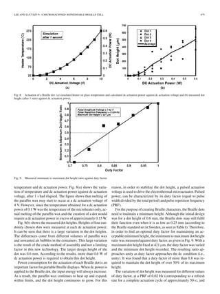
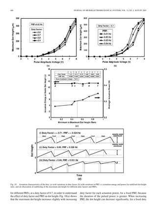
factor, because the average power is reduced, as shown in
Fig. 10(b). This demonstrates that the longer the duration of the
pulse, the more effective is the process of raising the Braille
dot. In addition, it is found from the relationship between
the duty factor and PRF that the melting of the paraffin wax
is a much more time-consuming process than solidification.
The reason is the difference between the small heating area
and large cooling area; heating is only performing from the
bottom heater area (i.e., two-dimensionally), but cooling is
by means of thermal conduction through the whole area (i.e.,
three-dimensionally) of the container. Therefore, a longer pulse
of power may be more effective than several shorter pulses. In
other words, actuation with a large duty factor and lower PRF is
most effective to maintain a relatively stable Braille dot height.
Since these measurements showed that the actuation dot
height depends significantly on the OFF duration (i.e., cooling
period), steady-state stabilization for a uniform dot height was
found using a reduced OFF duration whilst maintaining ap-
proximately constant actuation energy . If the ON duration
(i.e., to heating period ) is kept constant and changes are
only made to the OFF duration , the values of duty factor
and PRF are also varied. The energy per pulse is calculated
from
(2)
where is the measured resistivity of the microheater and
is now the pulsed amplitude voltage. Fig. 10(c) shows the ac-
tuation energy and power for a stabilized dot height ratio. As
the minimum to maximum dot height ratio tends to unity, dot
height does not undergo significant fluctuation. In Fig. 10(c),
point has the shortest OFF duration, whereby the cooling
time is reduced in order to maintain a stable dot height. Mean-
while, the average power increases with increasing duty factor.
A steady-state minimum to maximum dot height ratio of 0.9 was
achieved with an average power of 0.35 W by increasing the
duty factor to 0.94. Fig. 10(d) shows a simplistic representation
of dot height stabilization. When the OFF duration is longer than
the time requires for cooling the paraffin wax, the maximum dot
height is equal in each cycle, as shown in (i) of Fig. 10(d) . By re-
ducing the OFF duration, the molten paraffin wax does not fully
solidify before being heated again in the next cycle. Therefore,
even though the maximum dot height also initially increases, it
eventually reaches a stable maximum height. This phenomenon
is due to the complicated equilibrium relationship between heat
gain and loss, the expansion pressure of paraffin wax, coupled
with the elastic tension of the silicone rubber diaphragm.
VI. CONCLUSION
A Braille cell, having six dots, was fabricated using bulk mi-
cromachining and novel bonding techniques with silicon and
glass wafers, respectively. These cells were easily fabricated,
requiring only three masks, and a novel process using overglaze
paste was applied for high integrity wafer bonding. The max-
imum actuation dot height of the prototype Braille cell was 654
m. The dot height approached the target height after a 15 vol.%
expansion of the paraffin wax. To maintain a dot height at 50%
of its maximum, a duty factor of more than 0.8 was found, with
an average power of 0.30 W ( Hz). The dot height
increases with an increasing duty factor, with a fixed PRF, and
decreasing PRF, with a fixed duty factor. A stable maximum dot
height was achieved by reducing the cooling time.
A new technology has been developed for realizing a man-
ufacturable, and potentially low cost full-page Braille display.
Here, ultra thin micromachined refreshable Braille cells actu-
ated using hydraulic pressures from the volumetric expansion
of paraffin wax, have been successfully realized and tested. This
technology has used a specific paraffin wax, as the phase change
material, however, other paraffin wax compositions and, indeed,
other materials could be used to reduce the average actuation
power. Moreover, in order to reduce production cost even fur-
ther, the bulk micromachining of the silicon wafers and subse-
quent assembly can be replaced with micro hot embossing tech-
niques, applied to an appropriate alternative to silicon [28].
ACKNOWLEDGMENT
The authors would like to acknowledge Dr. J. Stagg for un-
dertaking the DRIE and Dr. M. Ahmad for his general advice.
In addition, special thanks go to Dr. K.-B. Kim, for undertaking
the DSC analysis of the Fluka 76 228 paraffin wax.
REFERENCES
[1] “Refreshable Braille Now and in the Years Ahead”, D. Blazie. [Online].
Available: http://www.nfb.org/bm/bm00/bm0001/bm000 110.htm
[2] [Online]. Available: http://www.metec-ag.de/b10.pdf
[3] J. M. Lee, C. R. Wagner, S. J. Lederman, and R. D. Howe, “Spatial low
pass filters for pin actuated tactile displays,” in IEEE Proc. HAPTICS
03, 2003, pp. 57–62.
[4] P. Kammermeier, M. Buss, and G. Schmidt, “Dynamic display of dis-
tributed tactile shape information by a prototypical actuator array,” in
IEEE Proc. Conf. Intelligent Robots and Systems, 2000, pp. 1119–1124.
[5] G. Moy, C. Wagner, and R. S. Fearing, “A compliant tactile display
for teletaction,” in IEEE Proc. Conf. Robot. Automation, 2000, pp.
3409–3415.
[6] P. M. Taylor, A. Moser, and A. Creed, “A sixty-four element tactile dis-
play using shape memory alloy wires,” Displays, vol. 18, pp. 163–168,
1998.
[7] P. M. Taylor, D. M. Pollet, A. Hosseini-Sianaki, and C. J. Varley, “Ad-
vances in an electrorheological fluid based tactile array,” Displays, vol.
18, pp. 135–141, 1998.
[8] K. Matsuura, T. Yakoh, and T. Aoyama, “Smooth tactile display in
mouse using electro-rheological gel,” in IEEE Proc. Symp. Ind. Elec-
tron., vol. 2, Jul. 2002, pp. 424–429.
[9] L. Yobas, M. A. Huff, F. J. Lisy, and D. M. Durand, “A novel bulk mi-
cromachined electrostatic microvalve with a curved-compliant structure
applicable for a pneumatic tactile display,” J. Microelectromech. Syst.,
vol. 10, no. 2, pp. 187–196, Jun. 2001.
[10] L. Yobas, D. M. Durand, G. G. Skebe, F. J. Lisy, and M. A. Huff, “A
novel integrable microvalve for refreshable Braille display system,” J.
Microelectromech. Syst., vol. 12, no. 3, pp. 252–263, Jun. 2003.
[11] F. V. Verdú and R. N. González, “Thermopneumatic actuator for tactile
displays,” in 18th Conf. Design of Circuits and Integrated Syst. DCIS
2003, 2003, pp. 629–633.
[12] S. F. Tibbitts, “High-output paraffin linear motors: Utilization in adap-
tive systems,” in SPIE Proc., vol. 1543, 1991, pp. 388–399.
[13] D. E. Dowen, “Design and implementation of a paraffin based microp-
ositioning actuator,” in SPIE, vol. 3132, 1997, pp. 127–134.
[14] N. Kabei, M. Kosuda, H. Kagamibuchi, R. Tashiro, H. Mizuno, Y.
Ueda, and K. Tsuchiya, “A thermal-expansion-type microactuator with
paraffin as the expansive material,” JSME Int. J., ser. C, vol. 40, no. 4,
pp. 736–742, 1997.
[15] E. T. Carlen and C. H. Mastrangelo, “Electrothermally activated paraffin
microactuators,” J. Microelectromech. Syst., vol. 11, no. 3, pp. 165–173,
Jun. 2002.](https://image.slidesharecdn.com/ieeeprotechnosolutions-ieeeembeddedprojectamicromachinedrefreshablebraillecell-160128120658/85/Ieeepro-techno-solutions-ieee-embedded-project-a-micromachined-refreshable-braille-cell-9-320.jpg)
![682 JOURNAL OF MICROELECTROMECHANICAL SYSTEMS, VOL. 14, NO. 4, AUGUST 2005
[16] L. Klintberg, M. Karlsson, L. Stenmark, J.-Å. Schweitz, and G. Thornell,
“A large stroke, high force paraffin phased transition actuator,” Sens.
Actuators A, vol. 96, pp. 189–195, 2002.
[17] L. Klintberg, M. Svedberg, F. Nikolajeff, and G. Thornell, “Fabrication
of a paraffin actuator using hot embossing of polycarbonate,” Sens. Ac-
tuators A, vol. 103, pp. 307–316, 2003.
[18] L. Klintberg, M. Karlsson, L. Stenmark, and G. Thornell, “A thermally
activated paraffin-based actuator for gas-flow control in a satellite elec-
trical propulsion system,” Sens. Actuators A, vol. 105, pp. 237–246,
2003.
[19] P. Selvaganapathy, E. T. Carlen, and C. H. Mastrangelo, “Electrother-
mally actuated inline microfluidic valve,” Sens. Actuators A, vol. 3647,
pp. 1–8, 2003.
[20] E. T. Carlen and C. H. Mastrangelo, “Surface micromachined
paraffin-actuated microvalve,” J. Microelectromech. Syst., vol. 11,
no. 5, pp. 408–420, Oct. 2002.
[21] M. Freund, R. Csikõs, S. Keszthelyi, and G. Y. Mõzes. (1982) Paraffin
Products: Properties, Technologies, Applications [Online]
[22] [Online]. Available: http://www.tiresias.org/reports/braille_cell.htm
[23] Handbook of Chemistry and Physics, 81st ed., CRC, Boca Raton, FL,
2000. D. R. Lide (Editor-in Chief) and H. P. R. Frederikse.
[24] M. Asheghi, K. Kurabayashi, R. Kasnavi, and K. E. Goodson, “Thermal
conduction in doped single-crystal silicon films,” J. Appl. Phys., vol. 91,
no. 8, 2002.
[25] A. D. McConnell, S. Uma, and K. E. Goodson, “Thermal conductivity
of doped polysilicon layers,” J. Microelectromech. Syst., vol. 10, no. 3,
Sep. 2001.
[26] D. G. Cahill and R. O. Pohl, “Lattice vibrations and heat transport in
crystals and glasses,” Ann. Rev. Phys. Chem., vol. 39, pp. 93–121, 1988.
[27] A. A. Ayón, R. L. Bayt, and K. S. Breuer, “Deep reactive ion etching:
A promising technology for micro- and nanosatellites,” Smart Mater.
Structures, vol. 10, pp. 1135–1144, 2001.
[28] X. C. Shan, R. Maeda, and Y. Murakoshi, “Micro hot embossing for
replication of microstructures,” Japan. J. Appl. Phys., vol. 42, pp.
3859–3862, Jun. 2003.
Jun Su Lee was born in South Korea in 1970. He re-
ceived the M.Sc. degree in metallurgical engineering
from Yonsei University, Seoul, in 1999.
From 2000 to 2001, he worked as an Intern
Researcher, within the metal processing research
center of the Materials Science and Technology
Division, Korea Institute of Science and Technology
(KIST, Seoul). Presently, he is working toward the
Ph.D. degree in electrical and electronic engineering
at Imperial College London, U.K. His current
interests are in intelligent materials for MEMS and
microfluidic devices.
Stepan Lucyszyn (M’91–SM’04) received the B.Sc.,
M.Sc., Ph.D., and C.Eng. degrees.
He joined Imperial College London, U.K., in June
2001, as a Senior Lecturer within the Optical and
Semiconductor Devices Group. Prior to this, he was
a Senior Lecturer with the University of Surrey,
Surrey, U.K. He was the Principal Investigator on,
and Coordinator for, two large multi-university
milimeterwave research projects, and also a Co-In-
vestigator on other projects. During the summer
of 2002, he was a Guest Researcher within the
Microelectromechanical Systems (MEMS) Laboratory, National Institute of
Advanced Industrial Science and Technology, Tsukuba, Japan. For the past
seven years, he has taught MMIC measurement techniques at the IEE Vacation
Schools on Microwave Measurements, National Physical Laboratory (NPL),
Teddington and Malvern, U.K. He has authored or coauthored 78 research
papers in both national and international conferences and journals in the broad
area of microwave and milimeter-wave engineering. In addition, he co-edited
and wrote three chapters in MMic Design (London, U.K.: IEE Press, 1995) and
four chapters in RFIC and MMIC Design and Technology (London, U.K.: IEE
Press, 2001).
Dr. Lucyszyn has recently been awarded two Engineering and Physical
Sciences Research Council (EPSRC) research grants. The first is to in-
vestigate milimeter-wave RF MEMS filters, utilizing conventional Surface
micromachining techniques on silicon. The second is to develop ultraquiet
milimeter-wave detectors using C AT’s nanowhiskers. He was the sole appli-
cant to represent Imperial College within the European Union’s Framework
VI Network of Excellence on Advanced MEMS for RF and Millimeter Wave
Communications (AMICOM).](https://image.slidesharecdn.com/ieeeprotechnosolutions-ieeeembeddedprojectamicromachinedrefreshablebraillecell-160128120658/85/Ieeepro-techno-solutions-ieee-embedded-project-a-micromachined-refreshable-braille-cell-10-320.jpg)