Downloaded 332 times
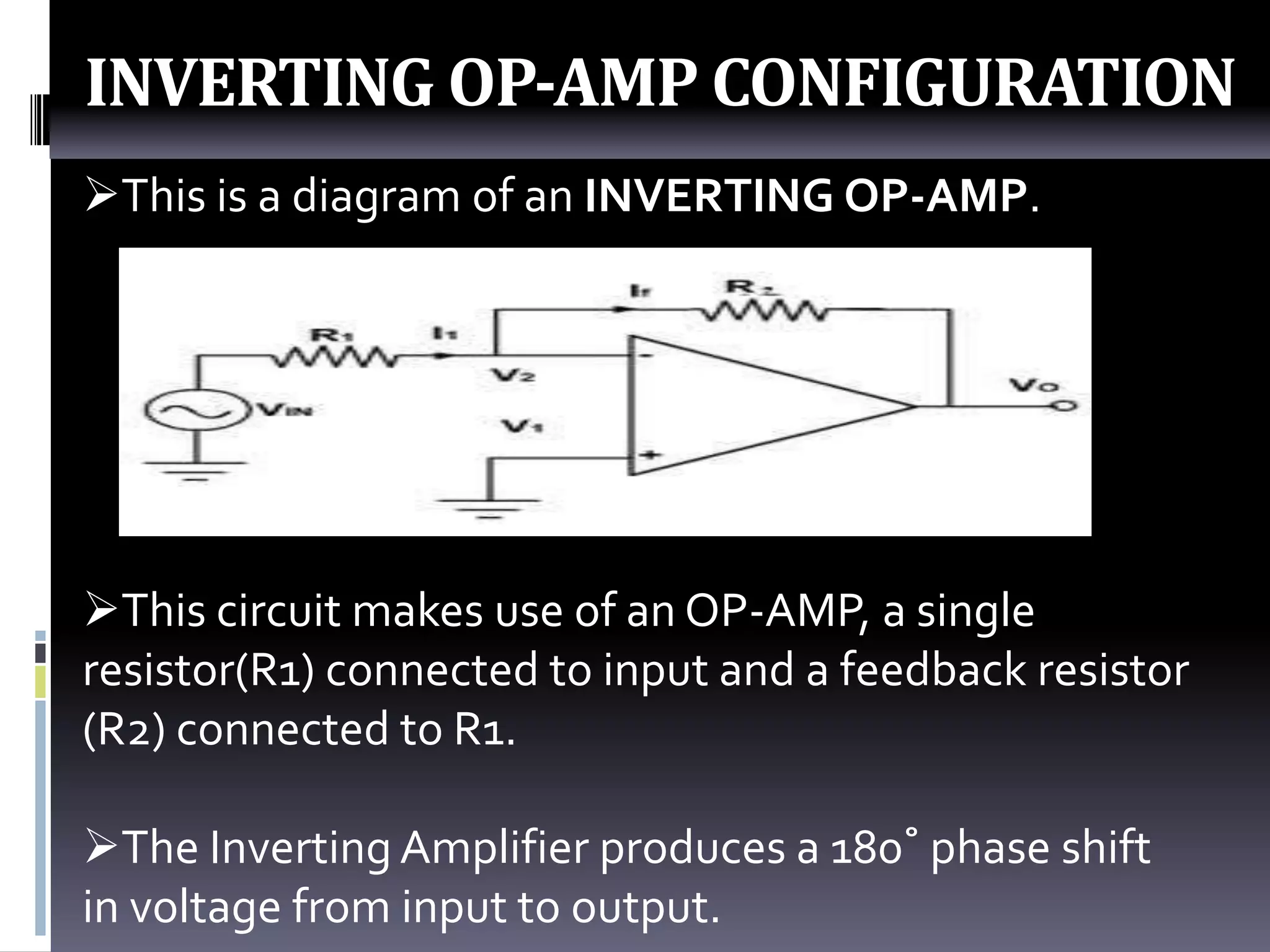
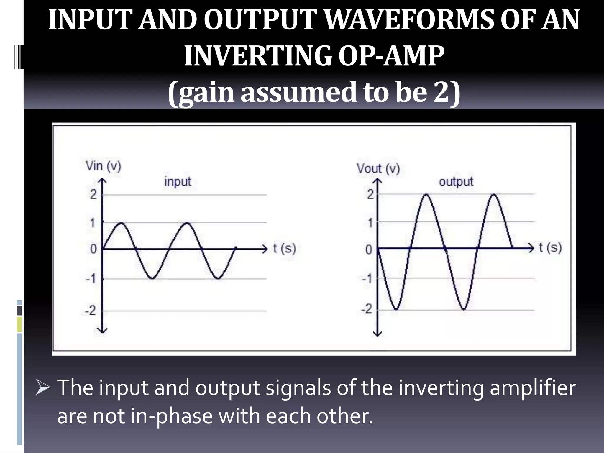

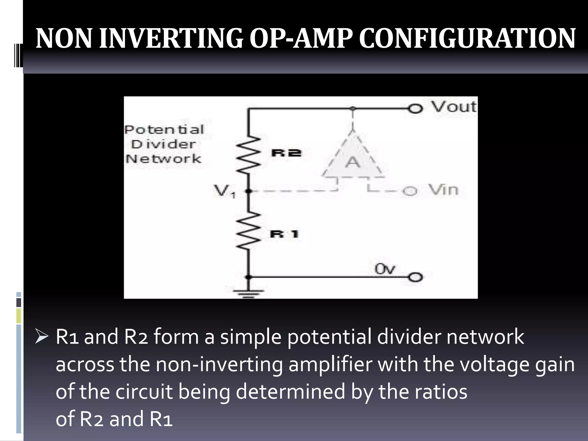


The document discusses two configurations of operational amplifiers (OP-AMPs): inverting and non-inverting. The inverting configuration uses a single resistor connected to the input and a feedback resistor, producing a 180 degree phase shift between input and output. The non-inverting configuration uses a resistor connected to ground and a feedback resistor, with the input directly applied to the non-inverting terminal and the output in phase with the input. Circuit diagrams, input/output waveforms, and voltage gain calculations are provided for both configurations.


