Downloaded 10 times
![Int. Journal of Electrical & Electronics Engg. Vol. 2, Spl. Issue 1 (2015) e-ISSN: 1694-2310 | p-ISSN: 1694-2426
45 NITTTR, Chandigarh EDIT-2015
Area Efficient 4-Bit Full Adder Design using
CMOS 90 nm Technology
Anurag Yadav
ME Scholar, Department Of ECE, NITTTR, Chandigarh, India
anuraglko2014@gmail.com
Abstract— To any digital circuit reduction of surface area is
one of the important parameter. Very large scale integration
VLSI provides the way to reduce the silicon area. In this
paper area efficient design of 4 bit full adder is developed.
Adder is one important element in computer arithmetic. It
uses for the addition of binary numbers. To design 4-bit full
adder two different methods are used in this paper. First is
fully auto CMOS design and second is semicustom design. In
first fully automatic CMOS design schematic and layout of 4-
bit full adder are developed. In second semicustom design
method layout of 4-bit full adder is developed by using
number of fringers. The layouts of both techniques are
simulated using 90nm technology. It can be observed from the
simulated results that semicustom layout results in 72%
reduction of silicon area as compared to full automatic
CMOS design.
Keywords— CMOS, VLSI, ADDER, MICROWIND
I. INTRODUCTION
Advances in CMOS technology increase interest in the
design of functions for digital systems. For over a century
changes in technology and operating constraints have
required improvements in design the functions in digital
systems [1]. With the technology scaling to micron the
speed of a circuit increases. Digital circuits make use of
arithmetic operations which encloses the study of
representation of numbers implementation of arithmetic
units in hardware. Among several arithmetic operations
addition is most functional and important arithmetic
operation. Adders are not only used for addition but it can
use for implementation of subtraction, multiplication and
division [2].
The adders selected for this design was also classified
according to the logic function realization. Using this
approach we have presented on analysis of the possible
impact of logic function selection and it is not just circuit
selection on the performance of the 4-bit full adder [3].
Adder selects on the basis of reduce surface area. So that 4
-bit full adder can implement in a small surface area. This
paper gives the analysis of surface area, width and height
parameters with different design method. To achieve high
performance hardware implementation it is necessary to
optimize the circuit’s critical path. In most of the circuits
this critical path is the carry chain. Which used in logic and
arithmetic operations [4]. In 4 bit full adder this carry chain
operation shows the carries transfer from bit to bit
position. In design 4 bit full Adder basic aim is to reduce
surface area and power consumption as minimum as
possible. In the constantly growing portable market it is
necessary to search for reduce surface area techniques with
power consumption. This work focuses specially on all
audio like mobile phones, audio chip sets and also in
biomedical applications where requirement of both surface
area and energy consumption are imposed [5]. In this time
many small sized adder multiplier or divider circuits have
been proposed that offer lower power consumption.VLSI
design can use to implement the reduced area circuit
design. There are several ways for logic designs each has
its own profits in terms of speed, chip surface area and
power dissipation [6].VLSI systems add many high
performance functional modules such as communication
and multi-media processors this is due to CMOS
technology [7].
II. 4 BIT FULL ADDER
Adder is very important element in computers. Binary
addition is one of the important operation in computer
arithmetic. The 4- bit full adder can add two four binary
numbers using four binary full adders with latency 4ta
where ta represents the delay of binary full adder [8]. It is
also known as ripple carry adder .An adder or summer is a
digital element that does addition. It adds binary number
and provide sum and carry at the output. CMOS circuit is
used for improving number of application with reduced
surface area and minimum power consumption [9]. The
most important applications in integrated circuits needed
arithmetic and logic circuits for calculation purpose. The
basic block element in 4- bit full adder that can be used for
calculation is a full adder circuit. Figure 1 shows the block
diagram of 4-bit full adder.
Figure1. Block diagram of 4- bit Full Adder.
A 0 , A1
, A 2
, A 3 , B0 , B1
, B 2
, B 3 are the input bits and
C IN ,C0 ,C1
, C 2
,are the carry input bits, S0 , S1
, S 2
, S 3
are the output bits C 3 is the output carry bit.
The basic adder is known as a full adder. It calculates
a one bit Sum and Carry from the two addends and a carry
in. The equations for full adder are as following –
S i
= a i
b i
c i
(1)](https://image.slidesharecdn.com/id18-150525174016-lva1-app6891/85/Area-Efficient-4-Bit-Full-Adder-Design-using-CMOS-90-nm-Technology-1-320.jpg)
![Int. Journal of Electrical & Electronics Engg. Vol. 2, Spl. Issue 1 (2015) e-ISSN: 1694-2310 | p-ISSN: 1694-2426
45 NITTTR, Chandigarh EDIT-2015
Area Efficient 4-Bit Full Adder Design using
CMOS 90 nm Technology
Anurag Yadav
ME Scholar, Department Of ECE, NITTTR, Chandigarh, India
anuraglko2014@gmail.com
Abstract— To any digital circuit reduction of surface area is
one of the important parameter. Very large scale integration
VLSI provides the way to reduce the silicon area. In this
paper area efficient design of 4 bit full adder is developed.
Adder is one important element in computer arithmetic. It
uses for the addition of binary numbers. To design 4-bit full
adder two different methods are used in this paper. First is
fully auto CMOS design and second is semicustom design. In
first fully automatic CMOS design schematic and layout of 4-
bit full adder are developed. In second semicustom design
method layout of 4-bit full adder is developed by using
number of fringers. The layouts of both techniques are
simulated using 90nm technology. It can be observed from the
simulated results that semicustom layout results in 72%
reduction of silicon area as compared to full automatic
CMOS design.
Keywords— CMOS, VLSI, ADDER, MICROWIND
I. INTRODUCTION
Advances in CMOS technology increase interest in the
design of functions for digital systems. For over a century
changes in technology and operating constraints have
required improvements in design the functions in digital
systems [1]. With the technology scaling to micron the
speed of a circuit increases. Digital circuits make use of
arithmetic operations which encloses the study of
representation of numbers implementation of arithmetic
units in hardware. Among several arithmetic operations
addition is most functional and important arithmetic
operation. Adders are not only used for addition but it can
use for implementation of subtraction, multiplication and
division [2].
The adders selected for this design was also classified
according to the logic function realization. Using this
approach we have presented on analysis of the possible
impact of logic function selection and it is not just circuit
selection on the performance of the 4-bit full adder [3].
Adder selects on the basis of reduce surface area. So that 4
-bit full adder can implement in a small surface area. This
paper gives the analysis of surface area, width and height
parameters with different design method. To achieve high
performance hardware implementation it is necessary to
optimize the circuit’s critical path. In most of the circuits
this critical path is the carry chain. Which used in logic and
arithmetic operations [4]. In 4 bit full adder this carry chain
operation shows the carries transfer from bit to bit
position. In design 4 bit full Adder basic aim is to reduce
surface area and power consumption as minimum as
possible. In the constantly growing portable market it is
necessary to search for reduce surface area techniques with
power consumption. This work focuses specially on all
audio like mobile phones, audio chip sets and also in
biomedical applications where requirement of both surface
area and energy consumption are imposed [5]. In this time
many small sized adder multiplier or divider circuits have
been proposed that offer lower power consumption.VLSI
design can use to implement the reduced area circuit
design. There are several ways for logic designs each has
its own profits in terms of speed, chip surface area and
power dissipation [6].VLSI systems add many high
performance functional modules such as communication
and multi-media processors this is due to CMOS
technology [7].
II. 4 BIT FULL ADDER
Adder is very important element in computers. Binary
addition is one of the important operation in computer
arithmetic. The 4- bit full adder can add two four binary
numbers using four binary full adders with latency 4ta
where ta represents the delay of binary full adder [8]. It is
also known as ripple carry adder .An adder or summer is a
digital element that does addition. It adds binary number
and provide sum and carry at the output. CMOS circuit is
used for improving number of application with reduced
surface area and minimum power consumption [9]. The
most important applications in integrated circuits needed
arithmetic and logic circuits for calculation purpose. The
basic block element in 4- bit full adder that can be used for
calculation is a full adder circuit. Figure 1 shows the block
diagram of 4-bit full adder.
Figure1. Block diagram of 4- bit Full Adder.
A 0 , A1
, A 2
, A 3 , B0 , B1
, B 2
, B 3 are the input bits and
C IN ,C0 ,C1
, C 2
,are the carry input bits, S0 , S1
, S 2
, S 3
are the output bits C 3 is the output carry bit.
The basic adder is known as a full adder. It calculates
a one bit Sum and Carry from the two addends and a carry
in. The equations for full adder are as following –
S i
= a i
b i
c i
(1)](https://image.slidesharecdn.com/id18-150525174016-lva1-app6891/75/Area-Efficient-4-Bit-Full-Adder-Design-using-CMOS-90-nm-Technology-1-2048.jpg)
![Int. Journal of Electrical & Electronics Engg. Vol. 2, Spl. Issue 1 (2015) e-ISSN: 1694-2310 | p-ISSN: 1694-2426
NITTTR, Chandigarh EDIT -2015 46
C 1i = a i
b i
+a i
c i
+ b i
c i
(2)
S = Sum at ith
satge.
C 1i = carry out of the ith
stage.
The n bit adder built from n one bit full adders is known as
a n- bit full adder or ripple carry adder because of the way
the carry is calculated [10]. Figure 2 shows the gate level
design of 4-bit full adder.
Figure2. Gate level design of 4-bit Full Adder
Reduction is an important parameter in designing Very
large scale integrated circuit. The growth of VLSI
technology increases because it provides portable devices
that has less surface area, power consumption minimum
and also provide better speed for operation of devices. To
reduce the size of circuit it is very important reduce
number of transistors in the designing of full adder. The
full adder is one of the most important element of many
digital VLSI circuits. Many improvements have been made
regarding its circuit. The aim of these improvements to
reduce the number of transistors. One of the main benefits
in reducing the number of transistors is to put more devices
on a single silicon chip. It results in reduce surface area of
design [11]. In this paper two different design methods are
used. These design methods provide better solution for
reduce the surface area with minimum power consumption.
Manufacturing of digital integrated circuits is challenging
job to reduce surface area with minimum power
consumption. Scaling improves transistor density and
functioning on a chip. It helps to improve frequency of
operation and speed. It improves high performance of the
chip [12].
III. FULLY AUTO CMOS DESIGN
In fully auto CMOS design uses DSCH to create schematic
of digital circuit. It gives the simulation in terms of timing
diagram. It is helpful in find out the behaviour of the
digital circuits. It provides the platform to create a verilog
file which compile in Microwind which creates the layout
of the schematic. In this paper 4-bit full adder is designed.
First create a schematic with the help of N-MOS and P-
MOS. Figure 3 shows the schematic of 4-bit Full Adder.
This Schematic is designed on DSCH. In designing of
schematic it is important to reduce number of N-MOS and
P-MOS .XOR gate is one important element in design of 4-
bit full adder .There are number of ways to design XOR
gate but it is important which required less area to design.
So to design area efficient digital circuit it is necessary to
use reduce number of N-MOS and P-MOS.
Figure3. Fully Auto CMOS Design of 4-bit Full Adder
Figure 4 shows the timing diagram for 4 bit full adder
where A 0 ,A1
, A 2
, A3 , B 0 , B1
, B 2
, B3 are the input bit
waveforms and C IN ,C 0 ,C1
, C 2
,are the carry input bit
waveforms, S 0 ,S1
, S 2
, S3 are the output bit waveform C
3 is the output carry bit waveform. It gives the behaviour of
4-bit full adder with different input waveforms.
Figure4.Timing Diagram Fully Auto CMOS Design.
Verilog file is created from DSCH. This file compiles in
Microwind. It gives the Layout of fully auto CMOS
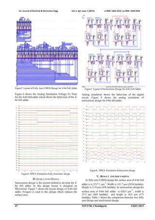
design of 4-bit full adder . Figure 5 shows the layout of
Fully Auto CMOS design of 4- bit full adder.](https://image.slidesharecdn.com/id18-150525174016-lva1-app6891/85/Area-Efficient-4-Bit-Full-Adder-Design-using-CMOS-90-nm-Technology-2-320.jpg)
![Int. Journal of Electrical & Electronics Engg. Vol. 2, Spl. Issue 1 (2015) e-ISSN: 1694-2310 | p-ISSN: 1694-2426
NITTTR, Chandigarh EDIT -2015 48
Table1. Comparison of parameters for two design method
Parameters Fully Auto
CMOS Design
Semicustom
Design
Width (μm) 101.7 33.5
Height (μm) 21.8 18.6
Surface Area(μm 2
)
2217.1 620.5
The semicustom design reduces the width from 101.7 μm
to 33.5 μm. In fully auto CMOS design, height reduces
from 21.8 μm to 18.6 μm. So semicustom design reduces
the surface area from 2217.1 μm
2
to 620.5 μm
2
. There is
some degradation in low level logic in the 4-bit full adder
in case of semicustom design. It will be improved in
future work.
Figure9. Graphical comparison of different parameters.
Figure 9 shows the graphical compression width and
height in μm between fully auto CMOS design and
semicustom design and it also shows graphical
compression surface area in μm
2
between fully auto
CMOS design and semicustom design.
VI.CONCLUSIONS
In this paper 4- bit full adder is designed with two design
method. One is Fully Auto CMOS design and second is
semicustom design. Second design which is semicustom
design has less steps to generate the layout of 4-bit full
adder as comparison with fully auto CMOS design. After
comparison of parameters in terms of width, height and
surface area. It has been observed that semicustom design
is better than fully auto CMOS design due to reduction in
width from 101.7 μm to 33.5 μm and height from 21.8 μm
to 18.6 μm. Due to reduction in width and height surface
area also reduces. Surface area in fully auto CMOS design
is 2217.1 μm
2
. Surface area of 4-bit full adder in
semicustom design is 620.5 μm
2
. So, semicustom design
reduces the surface area of 4-bit full adder. Simulation of
4-bit full adder is obtained with 90nm technology.
ACKNOWLEDGEMENT
I would like to thank Mr. Rajesh Mehra (Associate
Professor), Electronics and Communication Engineering
Department, National Institute of Technical Teachers
Training and Research, Chandigarh for his support and
valuable guidance.
REFERENCES
[1] Bart R. Zeydel, Dursun Baran, Vojin G. Oklobdzija “Energy
-Efficient Design Methodologies: High Performance VLSI
Adders” IEEE Journal of solid-state circuits, Vol. 45, no. 6,
pp.1220-1233, June 2010.
[2] Romana Yousuf and Najeeb-ud-din, “Synthesis of Carry
Select Adder in 65 nm FPGA” IEEE region 10 conference,
pp.1-6,2008
[3] Sohan Purohit and Martin Margala, “Investigating the
Impact of Logic and Circuit Implementation on Full Adder
Performance” IEEE Transaction Very Large Scale
Integration (VLSI) Systems, Vol. 20, no.7, pp.1327-1331,
July 2012.
[4] Scott Hauck, Matthew M. Hosler, and Thomas W. Fry
“High-Performance Carry Chains for FPGA’s” IEEE
Transaction on Very Large Scale Integration (VLSI)
Systems, Vol. 8, no. 2, pp.138-147, April 2000.
[5] Flavio Carbognani, Felix Buergin, Norbert Felber, Hubert
Kaeslin, and Wolfgang Fichtner, “Transmission Gates
Combined With Level-Restoring CMOS Gates Reduce
Glitches in Low-Power Low Frequency Multipliers” IEEE
Transaction on Very Large Scale Integration (VLSI)
Systems, Vol. 16, no. 7, pp. 830-836, July 2008.
[6] C.Senthilpari, S.Kavitha and Jude Joseph “Lower Delay and
Area Efficient Non-Restoring Array Divider by Using
Shannon Based Adder Technique” ICSE 2010 proc., melaka,
Malaysia, pp.140-144, 2010.
[7] Yongtae Kim, Yong Zhang and Peng Li “An Energy
Efficient Approximate Adder with Carry Skip for Error
Resilient Neuromorphic VLSI Systems” , computer –aided
design (ICCAD) IEEE/ACM international conference ,
pp.130-137,2013
[8] Keshab K. Parhi, “Low-Energy CSMT Carry Generators and
Binary Adders” IEEE Transactions on Very Large Scale
Integration (VLSI) Systems, Vol. 7, no. 4, pp. 450 -
462,December 1999
[9] Arun Gangwar and Rajesh Mehra “CMOS Design and Low
Power Full Adder Using .12 Micron Technology”
International Journal of research in computer applications
and robotics ISSN 2320-7345 Vol.1, Issue.2, pp1-6, March-
April 2013
[10] Waney Wolf, “Modern VLSI Design System on chip
Design”, Pearson Education third edition, pp. 342, 2008.
[11] Vandana Choudhary and Rajesh Mehra,“2- Bit Comparator
Using Different Logic Style of Full Adder” International
Journal of Soft Computing and Engineering (IJSCE) ISSN:
2231-2307, Volume-3, Issue-2, pp.227-279, May 2013.
[12] Pushpa Saini and Rajesh Mehra “Leakage Power Reduction
in CMOS VLSI Circuits”, International Journal of Computer
Applications (0975 – 8887)Volume 55– No.8, pp.42-48,
October 2012.
0
500
1000
1500
2000
2500
Width
(μm)
Height
(μm)
Surface
Area
Fully Auto
CMOS Design
Semicustom
Design](https://image.slidesharecdn.com/id18-150525174016-lva1-app6891/85/Area-Efficient-4-Bit-Full-Adder-Design-using-CMOS-90-nm-Technology-4-320.jpg)

This document describes the design of an area efficient 4-bit full adder using two different methods in a 90nm CMOS technology. The first method is a fully automatic CMOS design where the schematic and layout are developed automatically. The second method is a semicustom design where the layout is developed manually using fringes to reduce area. Simulation results show that the semicustom design reduces the silicon area by 72% compared to the fully automatic design, from 2217.1 μm2 to 620.5 μm2.


![[Deck] What's New in Spark-Iceberg Integration via DSV2.pptx](https://cdn.slidesharecdn.com/ss_thumbnails/deckwhatsnewinspark-icebergintegrationviadsv2-260210005337-25955b12-thumbnail.jpg?width=640&height=640&fit=bounds)


