
Recommended
Recommended
More Related Content
What's hot
What's hot (19)
Similar to Thermo Structural Analysis on Cylinder Head of 4 Stroke VCR Diesel Engine
Similar to Thermo Structural Analysis on Cylinder Head of 4 Stroke VCR Diesel Engine (20)
More from Dr. Amarjeet Singh
More from Dr. Amarjeet Singh (20)
Recently uploaded
Recently uploaded (20)
Thermo Structural Analysis on Cylinder Head of 4 Stroke VCR Diesel Engine
- 1. International Journal of Engineering and Management Research e-ISSN: 2250-0758 | p-ISSN: 2394-6962 Volume-10, Issue-2 (April 2020) www.ijemr.net https://doi.org/10.31033/ijemr.10.2.9 96 This work is licensed under Creative Commons Attribution 4.0 International License. Thermo Structural Analysis on Cylinder Head of 4 Stroke VCR Diesel Engine Dr. K Satyanaraya1 and A Swathi2 1 Associate Professor, Department of Mechanical Engineering, ANITS, INDIA 2 Assistant Professor, Department of Mechanical Engineering, Aditya College of Engineering and Technology, INDIA 2 Corresponding Author: swathiayithampudi@gmail.com ABSTRACT The main aim of the project is to analyse the design performance of VCR 4 stroke Diesel engine cylinder head at the compression ratio 16.5 using Ansys software. The basic modelling is done on CATIA V5 software. The design exposition can be done structurally and thermally in ansys. By the structural analysis the maximum and minimum von misses stress, total deformation can be determined, the maximum gas pressure required for this analysis is taken from the experimental set up of VCR engine. With the steady state thermal analysis we will get the maximum temperature distribution and total heat flux of the cylinder head with the initial pressure value. The results of both the expositions are used to decide the critical areas of the cylinder head which require further amendment and also the quality of design. If the maximum stress is less than the material strength of the cylinder head then the basic design criteria can be achieved. Keywords-- Cylinder, VCR, Diesel Engine, 4 Stroke, Crank I. INTRODUCTION The diesel engine is one kind of Internal Combustion engine. An internal means “Inside” and combustion is similar word for “Burning”, So an Internal Combustion engine is simply one where the fuel is burned inside the cylinder where power is produced. That’s very different from an External Combustion engine such as those used by old fashioned steam locomotives. CYLINDER: The cylinder of an I.C. engine contains the working fluid and guides the piston. The cylinder has to withstand high temperature due to the combustion of fuel; So that, some arrangement must be provided to cool the cylinder. AIR COOLED CYLINDER: Air cooled cylinder is commonly applicable for small engines say up to 20KW. In this type of cylinder fins are provided on the cylinder walls. Heat produced due to combustion in the engine cylinder and heat will be easily dissipated to air by help of provided fins. WATER COOLED CYLINDER: In this type of cylinder water jackets are provided around the cylinder. The water when circulated through the jackets, It absorb heat of combustion. Its mainly used in heavy engines having capacity above 20 KW. CYLINDER HEAD: In an Internal combustion engine the cylinder head located above the cylinder on top of the cylinder block. It closes the top of the cylinder and forming the combustion chamber. This joint is sealed by use of head gasket. The head also gives space for the passages that feed air and fuel to the cylinder and that allow the exhaust to escape. The cylinder head can also be a place to mount the valves, fuel injectors and spark plugs. The cylinder head are also either Air cooled or Water cooled. AIR COOLED CYLINDER HEAD: In this type of cylinder head fins are provided on the outer surface of cylinder head. Heat produced due to combustion in the engine cylinder and heat will be easily dissipated to air by help of provided fins on cylinder head. WATER COOLED CYLINDER HEAD: In this type of cylinder head water jackets are provided around the outer surface of cylinder head. The water when circulated through the jackets, It absorb heat of combustion. Loads acting on the cylinder head are :(1)Inertia force on cylinder due to unbalance forces from piston and connecting rod setup.(2) Vibration force in cylinder due to the speed variation in crankshaft.(3) Thermal load on cylinder and cylinder head due to improper temperature distribution. Mechanical load on cylinder head due to the improper stress distribution. (4) Fatigue load due to cyclic load on cylinder head.(5) Load on cylinder due to the explosion of fuel gases. (6)Load on cylinder due to compression of fuel gases. II. MATERIAL PROPERTIES The Cylinder head material should be readily cast with complicated internal shapes for both the coolant passages and for the inlet and exhaust ports. The material generally used are Grey Cast Iron and Aluminium alloys. Mostly preferred Cast Iron as its show good mechanical properties such as hardness, high melting temperature which are suitable for engine head. The properties of cast iron are illustrated below in table 1. TABLE 1
- 2. International Journal of Engineering and Management Research e-ISSN: 2250-0758 | p-ISSN: 2394-6962 Volume-10, Issue-2 (April 2020) www.ijemr.net https://doi.org/10.31033/ijemr.10.2.9 97 This work is licensed under Creative Commons Attribution 4.0 International License. Property name Value Tensile strength 414mpa Yield strength 276mpa Elongation 18% Density 7800 kg/m3 Poisons ratio 0.21 III. LITERATURE REVIEW The design and analysis of engine components has become more complex. One of these components is the engine cylinder head .The cylinder head of a diesel engine is usually subjected to periodically changing thermal and mechanical loads. Cylinder head simulation and strength analysis has been an important area of research which has attracted great research interim age. IV. GEOMETRY The image below shows the geometry of the cylinder head . The cylinder head is created by catia v5 and further imported to ansys software for further analysis. The following three types of boundary conditions are applied. Heat transfer co-efficient on the top of the cylinder head and pressure Forces which ia nearer to inlet and out let valves. Finite Element Model The element selected for meshing the piston model’s solid187 tetrahedral element. The meshing size Elements are 63,447 and no. Of nodes are 1,15,057. Fig 1:- Cylinder Head Geometric 3D Model. Fig 2:- Cylinder Head Meshing V. EXPERIMENTAL ANALYSIS & CALCULATIONS 5.1 Computerized VCR diesel engine specifications and Description Description: The setup consists of single cylinder, four stroke, VCR (Variable Compression Ratio) Diesel engine connected to eddy current type dynamometer for loading. Setup is provided with necessary instruments for combustion pressure and crank‐ angle measurements. These signals are interfaced to computer through engine indicator for Pθ & PV diagrams. Provision is also made for interfacing airflow, fuel flow, temperatures and load measurement. The setup has stand‐ alone panel box consisting of air box, two fuel tanks for duel fuel test, manometer, fuel measuring unit, transmitters for air and fuel flow measurements, process indicator and engine indicator. Rota meters are provided for cooling water and calorimeter water flow measurement. TABLE 2 Engine specifications Features Specifications Make Make Kirloskar Type Four stroke, Water cooled Diesel No of cylinders One Combustion Principle Compression ignition Max speed Crank Radius 55mm Connecting Rod Length 300mm Cylinder diameter 80mm Compression ratio Variable Stroke length 110mm
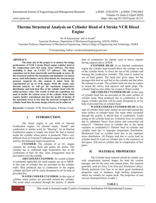
- 3. International Journal of Engineering and Management Research e-ISSN: 2250-0758 | p-ISSN: 2394-6962 Volume-10, Issue-2 (April 2020) www.ijemr.net https://doi.org/10.31033/ijemr.10.2.9 98 This work is licensed under Creative Commons Attribution 4.0 International License. TABLE 3 Readings from experimentation Features Specifications Load 21.27 N Speed 1470 rpm Fuel rate 2.06 kg/hr Air rate 16.20 m3/hr Water Flow 40.80 cc/sec Cooling Water inlet Temp 26.70 0C Cooling Water outlet Temp 30.800C 5.2 Calculations Based on these inputs following parameters for thermal analysis is calculated: Total heat lost through water jacket = 20.59 watts Average temperature of the cylinder head =348.22 0C Heat transfer coefficient on top surface (h) = 190.33 w/m2k Heat transfer coefficient of water coolant =140.33 w/mk 5.3 Variation of pressure Force with Crank Angle Fig 3:- Variations of pressure force with crank angle 5.4 Variation of temperature with Crank Angle Fig 4:- Variation of temperature with crank angle. VI. RESULTS By applying the boundary conditions heat transfer analysis is carried out. 6.1 Based on thermal analysis Fig 5:- Cylinder head total flux Fig 6:- Cylinder head temperature distribution TABLE 4 Steady State Thermal Analysis Type Maximum Minimum Temperature Distribution 1.27e^5 W/m^2 2.49e^-5 W/m^2 Total Heat Flux 211.96 degree centigrade 135.66 degree centigrade
- 4. International Journal of Engineering and Management Research e-ISSN: 2250-0758 | p-ISSN: 2394-6962 Volume-10, Issue-2 (April 2020) www.ijemr.net https://doi.org/10.31033/ijemr.10.2.9 99 This work is licensed under Creative Commons Attribution 4.0 International License. Fig 7:- Von Mises stress Fig 8:- Total Deformation Fig 9:- Fatigue Life Fig 10:- Factor of safety TABLE 5 Structural Analysis Type Maximum Minimum Von Mises stress 5 67e^7pa 0.0064pa Deformation 1.73e^-5m 0m Fatigue life 1e^6 1e^6 Factor of safety 15 1.62 VII. CONCLUSION Experimental investigation carried out on computerized VCR diesel test rig to determine the variation of pressure with crank angle in the cylinder at particular compression ratio. The temperature variation of gases was further evaluated using the results obtained from the experimentation. Using this experimental observations and they actual dimension of cylinder head, stress analysis was carried out with the aid of the modern software like catia and Ansys. The stress induced in piston and deformations were found to be within allowable limits. Further investigation is to be carried out at higher compression ratio. REFERENCES [1] Amit V. Paratwar & D.B. Hulwan. (2013). Surface temperature prediction and thermal analysis of cylinder head in diesel engine. International Journal of Engineering Research and Application (IJERA), 3(4), 892-902. [2] Baoxin Zhao, Dingwei Gao, Jingqian Shen, Zheng Zhao, Hao Guan, Gang Liu, & Ying Guan. (2012). Experiment and numerical analysis of temperature field of cylinder head based on a GW4D20 diesel engine. Available at: https://www.springerprofessional.de/en/experiment-and- numerical-analysis-of-temperature-field-of-cylind/3988158. [3] B N Niroop Kumar Gowd & Ramatulasi. (2014). Calculating heat transfer rate of cylinder fin body by varying geometry and material. International Journal of
- 5. International Journal of Engineering and Management Research e-ISSN: 2250-0758 | p-ISSN: 2394-6962 Volume-10, Issue-2 (April 2020) www.ijemr.net https://doi.org/10.31033/ijemr.10.2.9 100 This work is licensed under Creative Commons Attribution 4.0 International License. Mechanical Engineering and Robotics Research (IJMERR), 3(4), 642-657. [4] C.D. Rakopoulos, D.C. Rakopoulos, G.C. Mavropoulos, & E.G. Giakoumis. (2004). Experimental and theoretical study of the short term response temperature transient in the cylinder walls of a diesel engine at various operating conditions. Applied Thermal Engineering, Science Direct, 24(5-6), 679-702. [5] Cheng X., Wang X., Ming Y., Hongfei Z., & Ran Gao. (2015). Thermal-mechanical fatigue analysis of diesel engine cylinder head based on fluid-structure interaction. SAE Technical Paper 2015-01-0558. Available at: doi:10.4271/2015-01-0558. [6] F Zieher, F Langmayr, A Jelatancev, & K Wieser. (2005). Thermal mechanical fatigue simulation of cast iron cylinder heads. SAE Technical Paper. Available at: doi:10.427.1/2005-01-0796.