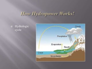
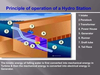
1) Hydroelectric power plants utilize the kinetic energy of flowing water to generate electricity. Water turns turbines which spin generators to produce electricity.
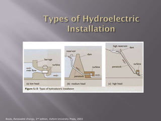
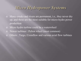
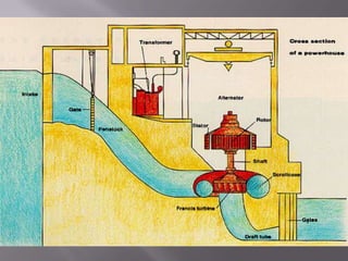
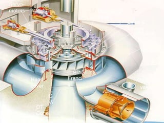
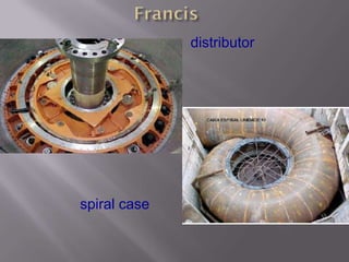
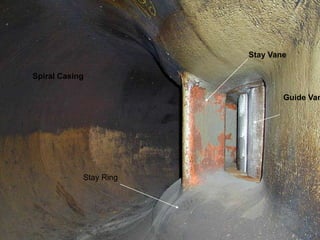
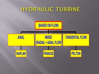
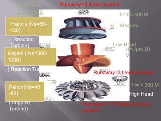
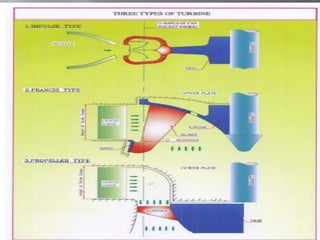
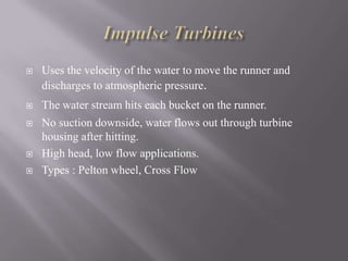
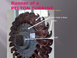
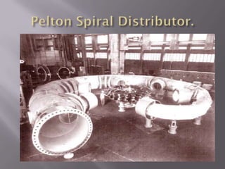
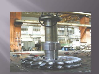
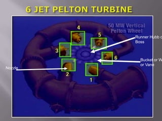
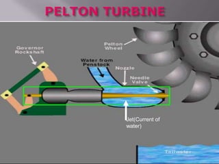
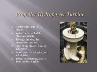
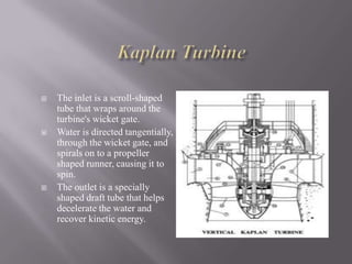
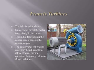
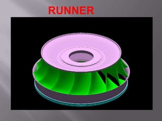
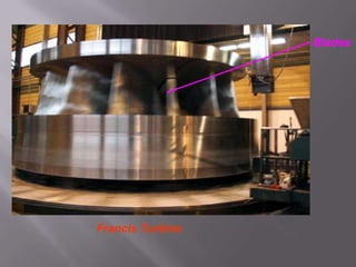
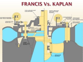
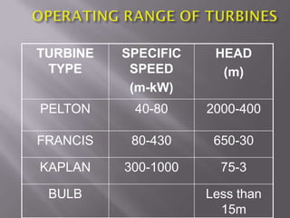
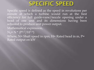
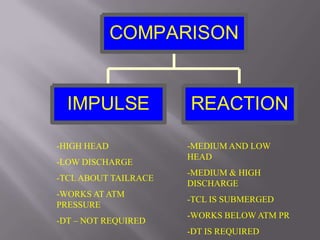
2) There are several types of hydroelectric turbines suited for different water head and flow conditions including Pelton, Francis, and Kaplan turbines. Pelton turbines work best for high head applications while Francis and Kaplan are used for lower heads and higher flows.
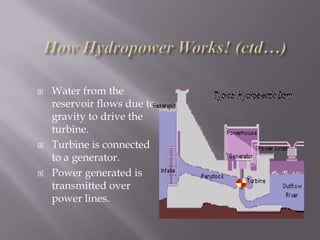
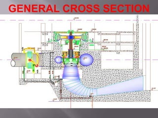
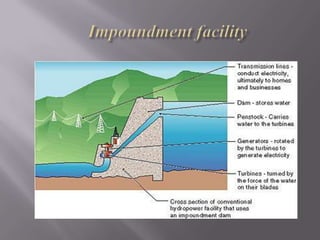
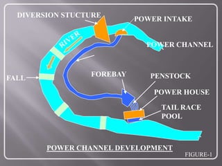
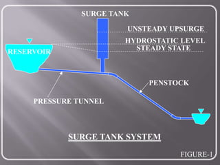
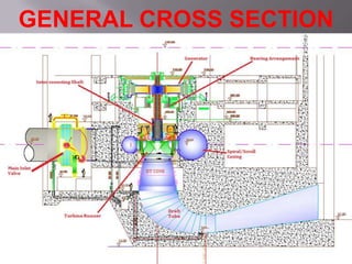
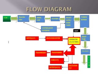
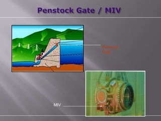
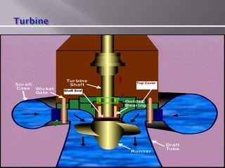
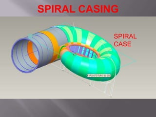
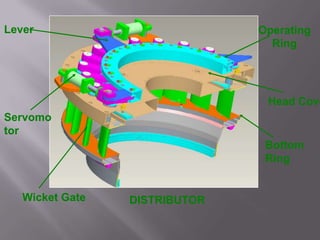
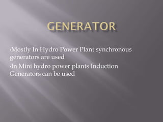
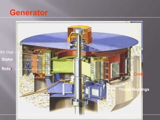
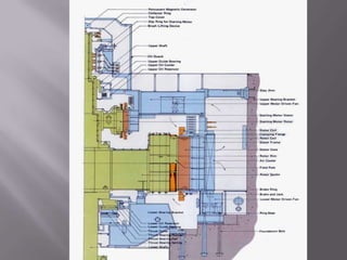
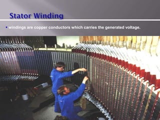
3) The key components of a hydroelectric power plant include an intake, penstock, turbine, generator, and tailrace. Water is diverted from a source through the intake and penstock before passing through the turbine which spins the generator to produce electricity which is then transmitted through power lines.