
Recommended
More Related Content
What's hot
What's hot (20)
Similar to Water Conductor Elements
Similar to Water Conductor Elements (20)
More from Satish Taji
More from Satish Taji (19)
Recently uploaded
Recently uploaded (20)
Water Conductor Elements
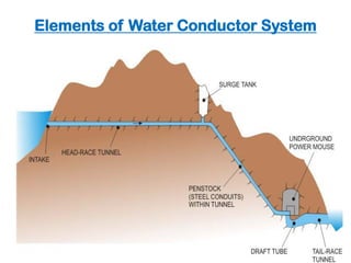
- 1. Elements of Water Conductor System Pressure Tunnels A typical section through a tunnel is shown in Fig. The initial portion of the tunnel from the intake up to the Surge-Tank is termed as the Head Race Tunnel (HRT) and beyond that it houses the penstock or steel-conduits, which sustains a larger pressure than the HRT.
- 2. Intake
- 3. Intake Structure An intake is provided at the mouth of a water conveyance system for a hydropower project. It is designed such that the following points are complied, as far as possible: There should be minimum head loss as water enters from the reservoir behind a dam or the pool behind a barrage into the water conducting system. There should not be any formation of vortices that could draw air into the water conducting system. There should be minimum entry of sediment into the water conducting system. Floating material should not enter the water conducting system.
- 4. Intake
- 5. Elements of intake 1. Trash rack and supporting structure. 2. Bell mouth entrance. 3. Gates with air vents. 4. Log/Trash boom.
- 6. Trash rack and screen • A trash rack is a wooden or metal structure, that prevents water-borne debris (such as logs, boats, animals, masses of cut waterweed, etc.) from entering the intake of water conveyance. • This protects penstock, and sluice gates from destruction and blockage due to debris, logs etc.
- 7. Trash Rack Trash rack Trash rack
- 8. Removing or cleaning process to trash rack
- 9. Smolt Screen
- 10. Gates It controls/regulates the entry of water into the intake.
- 11. Bell mouth entrance .
- 12. ICE,LOG,AND TRASH BOOMS Floating boom use to perform one or more of the following functions 1. Deflection of logs and trash from the intake screens. 2. Deflection of ice away from the intake. 3. Prevention of the boats form being carried into the intake
- 13. Trash Boom.
- 14. Intake Structure The position and location of an intake in a hydropower project would generally depend upon the type of hydropower development, that is, whether the project is of run-of-river type or storage type. Therefore, intake structure can be classified as: Run-of-river type intake Reservoir type intakes Intake also depends upon whether water conveyed through canal (power channel) or tunnel conduit
- 15. Intake Structure Run-of-river type intake Intakes adjacent to a diversion structure like a barrage. Here, an intake for a tunnel is placed upstream of the diversion structure to draw water from the pool
- 16. Intake Structure Run-of-river type intake For a canal intake, the head regulator resembles that of an irrigation canal intake. When the canal conveying water, also called the power canal, it leads to a Forebay before leading to the turbine unit, which is important element.
- 17. Intake Structure Run-of-river type intake For a canal intake, the head regulator resembles that of an irrigation canal intake. When the canal conveying water, also called the power canal, it leads to a Forebay before leading to the turbine unit, which is important element.
- 18. Intake Structure Reservoir type intakes Intakes for concrete dams are located on the upstream face of the dam. The face of the intake is rectangular and is reduced to a smaller rectangular section through a transitory shape known as the bell-mouth. From the smaller rectangular section, another transition is provided to change the shape to circular.
- 19. Intake Structure Reservoir type intakes Intakes for concrete dams are located on the upstream face of the dam. The face of the intake is rectangular and is reduced to a smaller rectangular section through a transitory shape known as the bell-mouth. From the smaller rectangular section, another transition is provided to change the shape to circular.
- 20. Intake Structure Reservoir type intakes Intakes for embankment dams are usually in the form of a conduit, which is laid below the dam and are provided in the form of a tower A tower type intake is constructed where there is a wide variation of the water level in the reservoir.
- 21. Intake Structure The choice and location of the intake structure depends upon the following factors. Type of development, that is, run-of-the-river or storage dam project; Location of power house and the dam ; Type of water conductor system, that is, tunnel, canal or penstock; Topographical features of area; The intake can often be located so as to enable it to be constructed before the level of the reservoir is raised.
- 22. Water Conductor System After flowing through the intake structure, the water must pass through the water conveyance system may be either of closed conduit type, (tunnel off-taking from upstream of the river diversion) or could be open-channels.
- 23. Water Conductor System Open channels These are usually lined canals to reduce water loss through seepage as well as to minimize friction loss. The design of canals for hydropower water conveyance follows the same rules as for rigid bed irrigation channels, and are usually termed as power canals. A power canal that off-takes from a diversion structure has to flow along the hill slope
- 24. Water Conductor System Open channels These are usually lined canals to reduce water loss through seepage as well as to minimize friction loss. The design of canals for hydropower water conveyance follows the same rules as for rigid bed irrigation channels, and are usually termed as power canals. A power canal that off-takes from a diversion structure has to flow along the hill slope
- 25. Water Conductor System Open channels A cross section of the canal would show that there would usually be high ground on one bank and falling ground on the other . It is important to stabilize the uphill cut-slope with some kind of protection in order to prevent fallout of loose blocks of stone into the canal.
- 26. Water Conductor System Open channels The power canal ends at a forebay, which is broadened to act as a small reservoir. From the forebay, intakes direct the water into the penstocks. There usually is a bye-pass channel which acts as a spillway to pass on excess water in case of a valve closure in the turbine of the hydropower generating unit. If such an escape channel is not provided, there are chances that under sudden closure of the valves of the turbines, surge waves move up the power canal. Hence, sufficient free board has to be provided for the canals.
- 27. Water Conductor System Open channels Forbay A forebay is an artificial pool of water located before and connected with penstocks Provided in case of run-off- river plants The major use of forebay is to distribution of flow of water in to penstocks , store water which is rejected by hydropower plant, Containing a trash rack and bye-pass channel.
- 28. Forebay connectingwith penstock and Containing a trash rack and bye-pass channel
- 29. Forebay
- 30. Water Conductor System Pressure Tunnels A typical section through a tunnel is shown in Fig. The initial portion of the tunnel from the intake up to the Surge-Tank is termed as the Head Race Tunnel (HRT) and beyond that it houses the penstock or steel-conduits, which sustains a larger pressure than the HRT.
- 31. Water Conductor System Pressure Tunnels The HRT may either be unlined (in case of quite good quality rocks) or may be lined with concrete. The surge tank is provided to absorb any surge of water that could be generated during a sudden closure of valve at the turbine end. Normally, the water level in the surge tank would be marginally lower than that at the intake and the difference of levels depends upon the friction loss in the HRT. Thus, when the HRT runs full, it is subjected to a much low pressure compared to the penstock.
- 32. Water Conductor System Pressure Tunnels The layout is usually governed by the geological features of the surrounding hills. Complicated geological conditions and extraordinary geological occurrences such as intra-thrust zones, very wide shear zones, geothermal zones of high temperature, cold/hot water springs, water charged rock masses, intrusions, fault planes, etc. should preferably be avoided. The Bureau of Indian Standards code IS: 4880-1976 “Code of practice for design of tunnels conveying water” (Parts 1 to 4) provide guidelines for design of a tunnel under various situations. Sound, homogeneous isotropic and solid rock formations are the most suitable for tunneling work.
- 33. Water Conductor System Penstock A penstock is one of the parts of conveyance system that construct from a steel or reinforced concrete to resist high pressure in the water conveyance system It may take off directly from behind a dam, from a forebay, or from the surge tank end of a head race tunnel
- 34. Water Conductor System Penstock It’s function is conveying water from forbay or surge tank to the turbine in the power house and it help to increase the kinetic energy of water that comes from the end of head race. A penstock is subjected to very high pressure and its design is similar to that for pressure vessels and tanks. However, sudden pressure rise due to valve closure of turbines during sudden load rejection in the electric grid necessitates that penstocks be designed for such water hammer pressures as well.
- 35. Water Conductor System Penstock Since penstocks convey water to the turbines and form a part of the hydropower water conveyance system, it is necessary that they provide the least possible loss of energy head to the flowing water. According to the Bureau of Indian Standards code IS: 11625- 1986 “Criteria for hydraulic design of penstocks”, the following losses may be expected for a penstock: a. Head loss at trash rock b. Head loss at intake entrance c. Friction losses, and d. Other losses as at bends, bifurcations, transitions, values, etc.
- 36. Water Conductor System Penstock Based on the above losses, the diameter of the penstock pipes have to be fixed, such that it results in an overall economy. This is because if the diameter of a penstock is increased, for example, the friction losses reduce resulting in a higher head at turbine and consequent generations of more power. But this, at the same time, increases the cost of the penstock. This leads to the concept of Economic Diameter of Penstock which is one such that the annual cost, including cost of power lost due to friction and charges of construction, maintenance, operation, etc. is the minimum.
- 37. Water Conductor System Penstock Types Buried penstocks or Embedded penstocks Exposed penstocks 1. Buried penstocks 2. Exposed penstocks
- 38. Water Conductor System Penstock Buried penstocks are supported continuously on the soil at the bottom of a trench backfilled after placing the pipe. The thickness of the cover over the pipe should be about 1.o to 1.2 m.
- 39. Water Conductor System Penstock Buried penstocks Merits The soil cover protects the penstock against effect of temperature variations, It protects the conveyed water against freezing. Buried pipes do not spoil the landscape. They are safer against rock slides, avalanches and falling trees.
- 40. Water Conductor System Penstock Buried penstocks Demerits The inspection and faults cannot be determined easily. It’s installation expensive Especially For large diameters and rocky soils. On steep hillsides, especially if the friction coefficient of the soil is low, such pipes may slide. Maintenance and repair of the pipe is difficult.
- 41. Water Conductor System Penstock Exposed penstocks: are installed above the terrain surface and supported on piers (briefly called supports or saddles). Consequently, there is no contact between the terrain and the pipe itself, and the support is not continuous but confined piers Merits The soil cover protects the penstock against effect of temperature variations, It protects the conveyed water against freezing. Buried pipes do not spoil the landscape. They are safer against rock slides, avalanches and falling trees.
- 42. Water Conductor System Penstock Exposed penstocks: Merits The possibility of continuous and adequate inspection during operation. Its installation is less expensive in case of large diameters of rocky terrain. Safety against sliding may be ensured by properly designed anchorages. Such pipes are readily accessible and maintenance and repair operations can be carried out easily
- 43. Water Conductor System Penstock Exposed penstocks: Demerits Full exposure to external variation in temperature. The water conveyed may freeze. Owing to the spacing of supports and anchorages significant longitudinal stresses may develop especially in pipes of large diameters
- 44. Buried Penstocks Surface Penstocks 1. Protection against temperature effect 1. Subjected to temperature variations 2. Landscape does not get affected 2. Landscape becomes scared with the Penstocks presence 3. Less accessible for inspection 3. Easily accessible for inspection 4. Greater expenses for large diameter penstocks in rocky soil 4. Economical under such circumstances 5. Does not require separate support. Does not require expansion joints 5. Requires anchorages for support necessitating in expansion joints Water Conductor System
- 45. The following are some major factors that must be considered in selecting a penstock route. Accessibility: o The route should be accessible to personnel and equipment required for pipe installation, inspection and maintenance. o In those areas where equipment access is difficult or impossible; installation and maintenance must be performed manually. Soil Conditions: o Soils along the pipeline should be examined to identify rock outcroppings, soft or unstable soils or other characteristics that would interfere with penstock installation or damage the penstock. Water Conductor System
- 46. • Natural or Man-Made Obstructions: • These include trees, roadways, buildings, stream crossings, and other features that require special care. • Gradient: • The penstock is best routed to take advantage of the natural downward gradient. • If the line cannot be located so as to have a constant downward gradient, an air relief valve or equivalent device is required at every local high point, and a drain valve is required at every local low point. Water Conductor System
- 47. Water Conductor System Penstock Penstock Alignment To determine the most economical alignment of a pipeline, the designer must investigate the site and make various layouts on topographic maps. He must then estimate material quantities for each layout and evaluate its constructability. When making the layouts, the penstock should be located on stable foundation sites such as along a ridge or a bench that has been cut into the mountainside, avoiding of troublesome sites such as underground water courses, landfill, fault zones and potential slide areas is quite important.
- 48. Water Conductor System Penstock Penstock Alignment To minimize costly anchors and costly pipe transition sections, vertical bends, horizontal bends and changes in diameter should be combined in a way to have them at the same location. Selection of the penstock alignment at site should be base on the following criteria.
- 49. Water Conductor System Penstock Penstock Alignment 1. Fore bay or surge tank location The penstock starts at the fore bay or surge tank, and its location should be chosen to optimize the lengths of headrace and penstock whilst achieving the required power output from the scheme. Penstock pipe is generally more expensive than headrace canal or tunnel therefore in most cases the fore bay or surge tank location should be chosen to give the minimum penstock length. However, sometimes a longer penstock may be economic to avoid the need for the headrace to cross an unstable slope.
- 50. Water Conductor System Penstock Penstock Alignment 2. Practical ground slope An ideal ground slope for the penstock alignment is between 1:1 and 1:2(V:H). The flatter the ground slope the less economic is the penstock since a longer pipe length is required for a lower head. Although a steep slope minimizes the penstock length, it will be difficult to manually lay the penstock, construct support piers and anchor blocks if the slope is greater than 1:1. Therefore, for penstock alignments on slopes steeper than 1:1, the added site installation cost may outweigh the savings made on the pipe costs..
- 51. Water Conductor System Penstock Penstock Alignment 3. Minimum number of bends Bends increase the head loss and require additional anchor blocks. Therefore the selected alignment should be as straight as possible, both in plan and elevation. Note that small bends can be avoided by varying the support pier heights for the exposed section and the trench depth for the buried section.
- 52. Water Conductor System Penstock Penstock Alignment 4. Space for powerhouse area The chosen alignment should be such that it is possible to construct a powerhouse at the end of the penstock. A river terrace well above the flood level is ideal for the powerhouse area. A route that is otherwise suitable for the penstock alignment but does not allow for the construction of the power house is inappropriate.
- 53. Water Conductor System Penstock Penstock Alignment 5. Stability Since the penstock alignment is on steep ground slopes and the pipe is under pressure, it is important for the alignment to be on stable ground. Any ground movement can damage the pipe, support piers and anchor blocks and in case of pipe bursts unstable slopes will cause further erosion and landslides.
- 54. Water Conductor System Penstock Penstock Alignment 6. Other site specific conditions Apart from the above criteria, there may be other site specific conditions that dictate the penstock alignment. For example, if the alignment crosses a local trail, road, canal, this section should either be buried or high enough above the ground such that people and cattle can walk underneath.
- 55. Water Conductor System Penstock - Accessories Bends Depending on topography, the alignment of the penstock is often required to be changed, in direction, to obtain the most economical profile.
- 56. Water Conductor System Penstock - Accessories Reducer piece In the case of very long penstocks, it is often necessary to reduce the diameter of the pipe as the head on the pipe increases. This reduction from one diameter to another should be effected gradually by introducing a special pipe piece called reducer piece.
- 57. Water Conductor System Penstock - Accessories Supports In the case of very long penstocks, it is often necessary to reduce the diameter of the pipe as the head on the pipe increases. This reduction from one diameter to another should be effected gradually by introducing a special pipe piece called reducer piece.
- 58. Water Conductor System Penstock - Accessories Expansion joints are installed in exposed penstocks to prevent longitudinal expansion or contraction when changes in temperature occur.