This document discusses hydroelectric power plants. It provides information on:
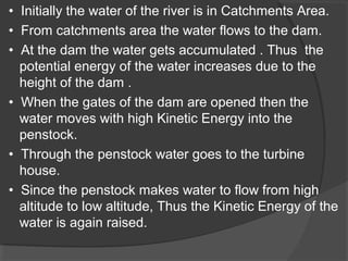
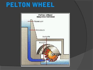
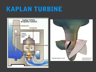
- How hydroelectric plants convert potential and kinetic energy of water into electricity.
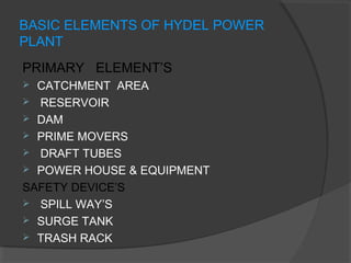
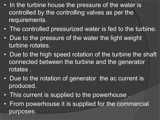
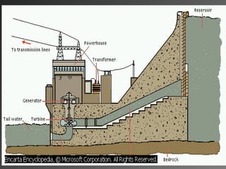
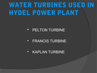
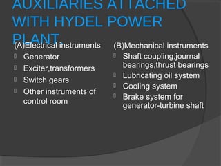
- The basic elements of hydroelectric plants include catchment areas, reservoirs, dams, turbines, generators, and safety devices.
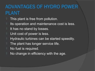
- Hydroelectricity accounts for 25% of global electricity generation capacity and provides a renewable source of energy without pollution.