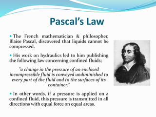
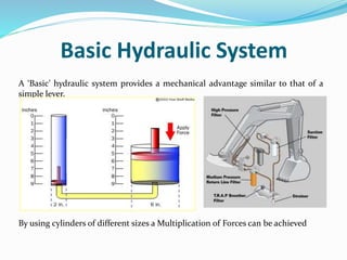
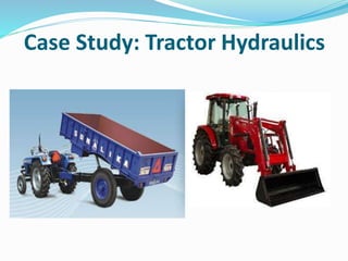
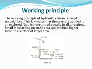
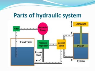
HYDRAULIC SYSTEM IN MOBILE
APPLICATION
Presented by
 BHARATH KUMAR S Mtech
Contents
 Introduction
 Basic hydraulic system
 Advantages of hydraulic system
 Application of hydraulic system
 Hydraulic system in mobile application
 Case study
 Working process
 Conclusion
Introduction
 The term ‘hydraulics’ refers to the power produced in
moving liquids.
 Hydraulic power in the form of water wheels and other
simple devices has been in use for centuries, but it wasn’t
until the 17th Century that the principles of hydraulics
were formulated into scientific law.
 Modern hydraulic systems are defined as;
The use of confined liquids to transmit power, multiply
force or produce motion efficiently.
Pascal’s Law
 The French mathematician & philosopher,
Blaise Pascal, discovered that liquids cannot be
compressed.
 His work on hydraulics led to him publishing
the following law concerning confined fluids;
"a change in the pressure of an enclosed
incompressible fluid is conveyed undiminished to
every part of the fluid and to the surfaces of its
container."
 In other words, if a pressure is applied on a
confined fluid, this pressure is transmitted in all
directions with equal force on equal areas.
Basic Hydraulic System
A ‘Basic’ hydraulic system provides a mechanical advantage similar to that of a
simple lever.
By using cylinders of different sizes a Multiplication of Forces can be achieved
Advantages of Hydraulics
 There are many advantages to utilising hydraulic systems within
airframe design.
 The system is often lighter in weight than a mechanical system
and have a low installation space requirement – hence ideal for
being buried within the airframe.
 Hydraulic systems can develop almost unlimited force or torque
 They are generally reliable: They either work or they do not
work!
 They are easy to maintain and are considered repair-friendly.
 They are smooth and responsive to operator inputs i.e. little or
no delay (or lag).
Applications of hydraulic
systems
 Industrial: Plastic processing machineries, steel making and primary
metal extraction applications, automated production lines, machine
tool industries, paper industries, loaders, crushes, textile
machineries, R & D equipment and robotic systems etc.
 Mobile hydraulics: Tractors, irrigation system, earthmoving
equipment, material handling equipment, commercial vehicles,
tunnel boring equipment, rail equipment, building and construction
machineries and drilling rigs etc.
 Automobiles: It is used in the systems like breaks, shock absorbers,
steering system, wind shield, lift and cleaning etc.
 Marine applications: It mostly covers ocean going vessels, fishing
boats and navel equipment.
 Aerospace equipment: There are equipment and systems used for
rudder control, landing gear, breaks, flight control and transmission
etc. which are used in airplanes, rockets and spaceships.
Case Study: Tractor Hydraulics
Introduction
 A unit responsible for lifting and lowering an agricultural
implement
 Function-draft control and weight transfer
 Fluid is confined inside pipelines, reservoir and cylinders
 Hydraulic pumps transfer the fluid from the reservoir to
the hydraulic system. This transfer raises the energy level of
the fluid by increasing its pressure. The motor provides the
power source for the pump
Working principle
The working principle of hydraulic system is based on
pascal's law. This law states that the pressure applied to
an enclosed fluid is transmitted equally in all directions.
Small force acting on small area can produce higher
force on a surface of larger area.
Why hydraulic system
 Simpler than mechanical linkage systems
 System is flexible enough
 Power can be engaged or disengaged using a simpler valve
 Input heavy forces can be controlled easily
 A good range of speed operation is possible
 Is safer than mechanical system
Parts of hydraulic system
 Reservoir
 Pump
 Valves
 Fluid
 Motor
 Hose
 Filter
 Cylinder
 Accumulator
Parts of hydraulic system
Reservoir Pump
It contains sufficient oil to move
the piston for lifting the load
 It forces the fluid from the reservoir to
the cylinder
 There are several types of hydraulic
pump, such as gear pump, plunger
pump, vane pump, and screw pump.
Gear pump is widely used in tractors.
Gear pump can flow a bigger amount
of oil, compared to plunger pump. The
oil pressure in the pump varies
from 150 to 200 kg/cm2.Schema
Relief valve Control valves
Relief valves are used in hydraulic
systems to limit the system pressure
to a specific set level. If this set level
is reached, the pressure relief valve
responds and feeds the excess flow
from the system back to the tank
Control valve is a type of valve,
which controls the movement of
hydraulic oil to have desired
direction, magnitude and speed of
lifting. This helps to determine
speed of movement for the
actuators.
Hydraulic motor Hydraulic Hose
A hydraulic motor converts
hydraulic energy into mechanical
energy: a rotating shaft. It uses
hydraulic pressure and flow to
generate torque and rotation.
Hydraulic hose is specifically
designed to convey hydraulic fluid to
or among hydraulic components,
valves, actuators, and tools. It is
typically flexible, often reinforced
and usually constructed with several
layers of reinforcement since
hydraulic systems frequently operate
at high or very high pressures.
Hydraulic filter Hydraulic accumulator
Hydraulic filters are used to
protect your hydraulic system
components from damage due to
contamination of oils caused by
particles
 A hydraulic accumulator stores
fluid under pressure
 Accumulators can take a specific
amount of fluid under pressure
and store it. The fluid is then
released when it´s required to
perform a specific task in the
hydraulic system
Working of Hydraulic system
 A simple hydraulic system consists of a pump which pumps
oil to a hydraulic ran. This pump may be driven from
tractors transmission system or it may be mounted on its
engine. This system consists of a cylinder with a close
filling piston like an engine cylinder. As the oil is pumped
in to the closed end of the cylinder, the piston is forced
along with it. The movement of the piston is transmitted to
the lower links by means of a cross shaft and lift rods. A
control valve controls the flow of oil and direction it back
to the reservoir. It allows the oil in the cylinder to flow out
again when the links are to be lowered. It also traps the oil
in the cylinder when the links are to be held at any height.
Hydraulic system

Hydraulic system

  • 1.
    HYDRAULIC SYSTEM INMOBILE APPLICATION Presented by  BHARATH KUMAR S Mtech
  • 2.
    Contents  Introduction  Basichydraulic system  Advantages of hydraulic system  Application of hydraulic system  Hydraulic system in mobile application  Case study  Working process  Conclusion
  • 3.
    Introduction  The term‘hydraulics’ refers to the power produced in moving liquids.  Hydraulic power in the form of water wheels and other simple devices has been in use for centuries, but it wasn’t until the 17th Century that the principles of hydraulics were formulated into scientific law.  Modern hydraulic systems are defined as; The use of confined liquids to transmit power, multiply force or produce motion efficiently.
  • 4.
    Pascal’s Law  TheFrench mathematician & philosopher, Blaise Pascal, discovered that liquids cannot be compressed.  His work on hydraulics led to him publishing the following law concerning confined fluids; "a change in the pressure of an enclosed incompressible fluid is conveyed undiminished to every part of the fluid and to the surfaces of its container."  In other words, if a pressure is applied on a confined fluid, this pressure is transmitted in all directions with equal force on equal areas.
  • 5.
    Basic Hydraulic System A‘Basic’ hydraulic system provides a mechanical advantage similar to that of a simple lever. By using cylinders of different sizes a Multiplication of Forces can be achieved
  • 6.
    Advantages of Hydraulics There are many advantages to utilising hydraulic systems within airframe design.  The system is often lighter in weight than a mechanical system and have a low installation space requirement – hence ideal for being buried within the airframe.  Hydraulic systems can develop almost unlimited force or torque  They are generally reliable: They either work or they do not work!  They are easy to maintain and are considered repair-friendly.  They are smooth and responsive to operator inputs i.e. little or no delay (or lag).
  • 7.
    Applications of hydraulic systems Industrial: Plastic processing machineries, steel making and primary metal extraction applications, automated production lines, machine tool industries, paper industries, loaders, crushes, textile machineries, R & D equipment and robotic systems etc.  Mobile hydraulics: Tractors, irrigation system, earthmoving equipment, material handling equipment, commercial vehicles, tunnel boring equipment, rail equipment, building and construction machineries and drilling rigs etc.  Automobiles: It is used in the systems like breaks, shock absorbers, steering system, wind shield, lift and cleaning etc.  Marine applications: It mostly covers ocean going vessels, fishing boats and navel equipment.  Aerospace equipment: There are equipment and systems used for rudder control, landing gear, breaks, flight control and transmission etc. which are used in airplanes, rockets and spaceships.
  • 8.
  • 9.
    Introduction  A unitresponsible for lifting and lowering an agricultural implement  Function-draft control and weight transfer  Fluid is confined inside pipelines, reservoir and cylinders  Hydraulic pumps transfer the fluid from the reservoir to the hydraulic system. This transfer raises the energy level of the fluid by increasing its pressure. The motor provides the power source for the pump
  • 10.
    Working principle The workingprinciple of hydraulic system is based on pascal's law. This law states that the pressure applied to an enclosed fluid is transmitted equally in all directions. Small force acting on small area can produce higher force on a surface of larger area.
  • 11.
    Why hydraulic system Simpler than mechanical linkage systems  System is flexible enough  Power can be engaged or disengaged using a simpler valve  Input heavy forces can be controlled easily  A good range of speed operation is possible  Is safer than mechanical system
  • 12.
    Parts of hydraulicsystem  Reservoir  Pump  Valves  Fluid  Motor  Hose  Filter  Cylinder  Accumulator
  • 13.
  • 14.
    Reservoir Pump It containssufficient oil to move the piston for lifting the load  It forces the fluid from the reservoir to the cylinder  There are several types of hydraulic pump, such as gear pump, plunger pump, vane pump, and screw pump. Gear pump is widely used in tractors. Gear pump can flow a bigger amount of oil, compared to plunger pump. The oil pressure in the pump varies from 150 to 200 kg/cm2.Schema
  • 15.
    Relief valve Controlvalves Relief valves are used in hydraulic systems to limit the system pressure to a specific set level. If this set level is reached, the pressure relief valve responds and feeds the excess flow from the system back to the tank Control valve is a type of valve, which controls the movement of hydraulic oil to have desired direction, magnitude and speed of lifting. This helps to determine speed of movement for the actuators.
  • 16.
    Hydraulic motor HydraulicHose A hydraulic motor converts hydraulic energy into mechanical energy: a rotating shaft. It uses hydraulic pressure and flow to generate torque and rotation. Hydraulic hose is specifically designed to convey hydraulic fluid to or among hydraulic components, valves, actuators, and tools. It is typically flexible, often reinforced and usually constructed with several layers of reinforcement since hydraulic systems frequently operate at high or very high pressures.
  • 17.
    Hydraulic filter Hydraulicaccumulator Hydraulic filters are used to protect your hydraulic system components from damage due to contamination of oils caused by particles  A hydraulic accumulator stores fluid under pressure  Accumulators can take a specific amount of fluid under pressure and store it. The fluid is then released when it´s required to perform a specific task in the hydraulic system
  • 18.
    Working of Hydraulicsystem  A simple hydraulic system consists of a pump which pumps oil to a hydraulic ran. This pump may be driven from tractors transmission system or it may be mounted on its engine. This system consists of a cylinder with a close filling piston like an engine cylinder. As the oil is pumped in to the closed end of the cylinder, the piston is forced along with it. The movement of the piston is transmitted to the lower links by means of a cross shaft and lift rods. A control valve controls the flow of oil and direction it back to the reservoir. It allows the oil in the cylinder to flow out again when the links are to be lowered. It also traps the oil in the cylinder when the links are to be held at any height.