The document discusses various accessories used in hydraulic systems including power units, reservoirs, and accumulators. It provides details on the components and functions of each accessory. Power units supply energy and fluid flow for the system. Reservoirs store and filter fluid, settling contaminants. Accumulators store potential energy from compressed gas or springs to meet peak energy demands the prime mover cannot.


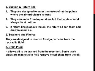


![Cytopathology Of Cerebrospinal Fluid[1]Power Point](https://cdn.slidesharecdn.com/ss_thumbnails/cytopathologyofcerebrospinalfluid1power-point-1230479978520994-2-thumbnail.jpg?width=640&height=640&fit=bounds)


![Introduction-to-Hydraulic-Accumulatorssss (1)[1] 1 (2).pptx](https://cdn.slidesharecdn.com/ss_thumbnails/introduction-to-hydraulic-accumulatorssss1112-251217204059-16265c2e-thumbnail.jpg?width=640&height=640&fit=bounds)


