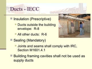
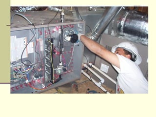
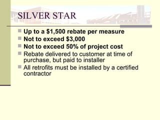
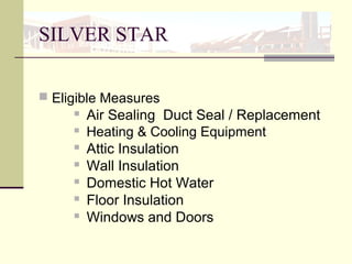
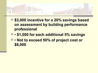
Quality HVAC System
Installation
The goal for a Heating, Ventilation and Air
Conditioning (HVAC) system is to provide proper air
flow, heating, and cooling to each room
Class Sponsors
Nevada Housing Division
Nevada State Office of Energy
Instructor
Barbara Collins
Energy Rated Homes
 Building Science Consultant
 Certified Green Building
Verifier
 Certified HERS Rater
 Energy Star Homes Partner
Class Objectives
 Understand IECC Duct Sealing and Testing
Requirements
 Learn How to Meet IECC and Energy Star
Homes Requirements
 Learn How to Avoid Common Installation
Problems
 Learn About IECC Requirement for Manual J
Load Calculation
 Learn About Proposed Retrofit Programs and
Rebates For Growing Your Business
HVAC System
 Poor design and installation increases energy
costs 10 –30%
 Sizing
 Design
 Installation
Ducts - IECC
 Insulation (Prescriptive)
 Ducts outside the building
envelope: R-8
 All other ducts: R-6
 Sealing (Mandatory)
 Joints and seams shall comply with IRC,
Section M1601.4.1
 Building framing cavities shall not be used as
supply ducts
Duct Tightness Tests
 All ducts, air handlers, filter boxes and building
cavities used as ducts shall be sealed (Section
403.2.2)
 Duct tightness shall be verified by testing
 Only Exception: Duct tightness test is not
required if the air handler and all ducts are
located within conditioned space
Mandatory Requirements
Current Code Requirements
 Must comply with all aspects of UL181
standards
 Fittings, joints & seams of duct system shall
be made substantially air tight by means of
tapes, mastics, gasketing or other means.
SEAL DUCTS,
SAVE ENERGY
Sealing ducts is a cost-effective
energy efficiency practice that gives
a high return on investment
Home Energy Use
 Residential energy use 22% of U.S. total
 25% of carbon emissions in U.S.
 Heating & cooling is 40 – 60 % of home
energy use
Why seal ducts
 Leaks waste energy and money
 Average system leakage
 New construction 20%
 Existing homes 30%
 Duct sealing reduces heating and cooling
energy losses and saves money
Other Problems
 Duct leakage reduces air flow, conditioned air
isn’t delivered to rooms which can cause wide
temperature swings between rooms
 IAQ issues with return leaks drawing in air
from attics, garages, crawlspaces
 Pressure differentials can cause excess
building air leakage and backdrafting
Duct Tightness Tests
 Post construction tests
 Option 1
 Leakage to outdoors: ≤8 cfm/per 100 ft2
of
conditioned floor area
 OR
 Option 2
 Total leakage: ≤12 cfm/per 100 ft2
of
conditioned floor area
Mandatory Requirements
Duct Tightness Tests
Rough-in test Options
 Option 1
 Total leakage ≤6 cfm/per 100 ft2
of conditioned
floor area
OR
 Option 2
If air handler not installed at time of test total air
leakage ≤4 cfm/per 100 ft2
Mandatory Requirements
Exceptions: Duct tightness test is not required if
the air handler and all ducts are located within
conditioned space
Ventilation
Outdoor air intakes and exhausts shall have
automatic or gravity dampers that close when
the ventilation system is not operating
Mandatory Requirements
Tested at a pressure differential of 0.1 in
w.g. (25Pa) across entire system,
including manufacturer’s air handler
enclosure
Mastic Sealant
Non-toxic – Low VOC
Green credits
Dries to touch in about ½
hour
Recommended Set time
= 20 hours
More on Mastic
 High strength adhesive compound
 Usually applied by trowel, brush, caulking gun
or hand
 3 types- water-based; solvent-based; and
two-component curing systems
 Water-based is the safest and easiest to use
It performs as well and in some cases better
than the other 2
VOCs in mastics
 Volatile organic compounds
 In water-based mastics, the only volatile
compound is water which is inorganic
 VOCs are infinitesimally small (not
recordable)
 Water-based mastics pose a low health risk
compared to solvent-based and two-
component mastics
 Safer for the user, better IAQ, greener
How to apply mastic
 Step 1 - Clean Duct Surface
 Wipe dust oil and grease from the duct surface
 Step 2 - Apply the mastic
 Gaps less than 1/4″, load brush with mastic
and coat entire joint with a continuous strip
 Use brush end to work mastic into joint
 Spread mastic at least one inch on each side
of the joint.
 The mastic should be thick enough to hide the
metal surface of the duct.
Mesh for Gaps
 If gap is larger than 1/4
inch use fiberglass
mesh too
 If mesh is sticky on
one side, cut enough
to cover joint, press in
place, then completely
cover it with mastic.
 If mesh does not have
a sticky side, apply a
thin layer of mastic,
press mesh into the
mastic, then apply a
finish layer of mastic.
Tools & Materials
Head lamp, hat with light, or flashlight
A work board to span joists in attics
Gallon pail and 2-3 caulk tubes of mastic
Caulk Gun, mastic brush, fin and plenum brush
Roll of mesh
2-3 pairs of latex gloves
2-3 cloths, can of coil and fin cleaner to wipe joints
clean before applying mastic and clean up
Utility knife and telescoping mirror
Pliers, screw driver and tin snips
For Sealing Existing Systems
Sealing Priorities
1. Disconnected components
2. Connections between the air handling unit
and the plenums
3. All seams in the air handling units and
plenums, takeoffs, boots, and other
connections, especially site-built items.
 Remove tie holding duct
to connection
 Roll back insulation and
outer cover
 Seal inner core with
mastic and band
 Roll insulation down
and vapor barrier/outer
cover
 Put band and seal with
mastic
 Wrap Ducts with insulation
 Insulation may be installed over wet mastic
but do not move the ducts too much or mastic
seal could be damaged.
 All duct support work should be done before
applying mastic
 Wait 2 -4 hours and water based mastic will
be dry to the touch
AIRTIGHT DUCT SYSTEM
Boots and Cans
 Seal seams with
mastic
Thin mastic will crack
Make seal permanent
Plug Don’t Paint
Thick as a Nickel = .077 in
1/16 inch = .0625 in
AIRTIGHT DUCT SYSTEM
Flexible Ducts
Seal inner sleeve & outer
sleeve
 Plastic strap holds the
inner liner firmly to the
duct or fitting.
 Mastic seals liner to
connection and covers the
end of the liner
 Use drawband to hold
outer sleeve (vapor
barrier)
Vapor barrier should be complete.
All holes, rips, and seams must be
sealed with mastic or approved tape
AIRTIGHT DUCT SYSTEM
Metal Ducts and Plenums, Duct Board
Boxes
 Openings greater than 1/4 inch should be
sealed with mastic and mesh
 Openings less than 1/4 inch should be
sealed with mastic
 Special attention to collar connections to
duct-board and/or sheet metal; seal around
the connection with mastic
Ts Ys & Ls
 Use mesh tape to
strengthen the joint
where ducts of different
shapes meet.
 Seal all seams, even
manufactured ones.
Sealant applied, still leaks
FABRICATION & INSTALLATION
GUIDELINES
 The air handler box should be air-tight
Air Handler Leaks
Mechanical Systems & Equipment
AHUs & Plenums
 Fill all openings for
wiring, plumbing and
refrigerant lines.
 Seal all seams in the air
handler and plenums.
 Tape around access
panels, so they can be
opened for service.
AIRTIGHT HVAC SYSTEM
Air handlers on platforms
 May be located in a closet indoors
 Framers must be told not to put plywood top
on before walls are sheetrocked (or duct
board) to underside of platform floor
 All wall surfaces must be sheetrocked next to
and in platform
 Seal all joints
Boots
 Seal all joints, including
manufactured seams.
 The transition between
the duct and boot may
require mesh tape.
AIRTIGHT DUCT SYSTEM
All Duct Types
Register boxes should be sealed to the drywall or floor
with caulking or mastic
AIRTIGHT DUCT SYSTEM
All Duct Types
Register boxes should be sealed to the drywall or floor
with caulking or mastic
SHEET MEATAL CONNECTIONS
 Start the inner fitting into the outer fitting
 Apply a 2” wide band of mastic 20 – 30 mils thick to
the exposed part of the inner fitting
 Fully seat the joint and mechanically fasten with
sheet metal screws or rivets
 Apply a 2.5” wide band of mastic 20 – 30 mils thick to
the outside of the joint covering the screws or rivets
and joint gap
 Allow at least 12 hours drying time before starting
system
 Temperature and humidity conditions can vary,
longer dry times may be required
Locating ducts within conditioned
space
 Within conditioned space means within
insulated space and within the air barrier
boundary.
 Attics and crawlspaces are not conditioned
space
 Critical that space is truly indoors and sealed
from unconditioned areas
 Multi-level dwellings more easily
accommodate ducts in conditioned space
Ducts in Unconditioned Space
 Usually ducts are located in attics and
crawlspaces
 Conduction losses are amplified by big
temperature differences
 Convection losses by leakage
Long duct runs in attics lose 15%+ of cooling
capacity before end
Benefits of locating ducts in
conditioned space
 Ducts can be smaller
 May have shorter runs reduce pressure drop
and improve efficiency
 Can reduce HVAC system costs by reducing
loads
 Reduce conduction losses
 Improve comfort
 No Testing in 09 IECC
EXISTING HOMES
 In existing homes, not unusual to find
disconnected duct components, takeoffs
loose from ducts or ducts disconnected from
register boots
EXISTING HOMES
 Leaks connected to the outdoors are more
important than leaks inside home’s thermal
envelope
 Holes near the air handler are more important
than distant holes with relatively low
pressures
 Supply system leaks waste more energy than
return system leaks
 Furnaces
Equipment Sizing
 Load calculations determine the
proper capacity (size) of equipment
 Goal is big enough to ensure
comfort but no bigger
 Calculations with ACCA Manual J
protocol or other approved methods
Mandatory Requirements
Oversizing
What do you get when you combine cognitive
bias with inaccurate information?
Oversizing
 Old Rules of Thumb
 One Size Fits All
 US Department of Energy
 Most systems are oversized, increasing
installation cost for every house
Oversizing
 Sizing example
House with standard metal windows w/ .75 U-
Value and .88 SHGC and 20% duct leakage
 Calculated Sensible cooling load = 58880 Btu
Oversizing
 Sizing example
 Same house with Low-E windows and tight
duct system @ 5% leakage
 Sensible cooling load = 43877 Btu
 Average of 1-2” decrease in duct diameter
sizes
Oversizing
 Installation cost is higher
 Operating cost over life of equipment is
higher
 Can cause comfort problems
 Improvements in building envelope should
reduce loads
Right Sizing
 Costs less to install – saves builder money
 Costs less to operate - not starting and
stopping all the time
 Short cycling can cause bigger swings in
supply air, less comfort
 Better humidity control
DESIGN HVAC SYSTEM
Loads and CFM Calculation
 ACCA Manual J Load Calculation or
equivalent required
 Calculate heat loss and heat gain for each
room
Total room loads to determine system
requirements.
Manual J –Load Calc
 The local climate – ASHRAE 30 year average
 Size, shape, and orientation of the house
 Insulation levels
 Window area, location, and type
 Air infiltration rates
 Number of occupants
 Types and efficiencies of lights and major home
appliances (which give off heat)
 ACCA - Air Conditioning Contractors of America
www.acca.org
A Quality HVAC System
 Be properly sized to provide correct air flow, and
meet room-by-room calculated heating and cooling
loads.
 Have sealed ductwork that will provide proper air
flow.
 Be installed with a return system designed to provide
correct return air flow.
 Have balanced air flows between supply and return
systems to maintain neutral pressure in the home.
 Be properly charged with refrigerant
“It’s tough to make
predictions,
especially about
the future.”
- Yogi Berra
U.S. Dept of Energy
30/30 Vision
2012 IECC 30% More Stringent 2006 IECC
More verification testing
Ductwork
 Single most important energy measure for
most homes- low hanging fruit
 Locating inside conditioned space is optimal
 Seal joints with mastic not duct tape
Equipment Size
 Oversizing is common and expensive –
upfront and during life
 Sizing properly can reduce cost and help pay
for increased cost of other efficiency features
HOME STAR Program
 $6 Billion Residential Retrofit
 SILVER STAR
– $3.6 Billion
 GOLD STAR
- $1.8 Billion
 Financing / QA / Admin
– $600 Million
Recovery Through Retrofit
 Construction
24.7% unemployment in construction industry
38% drop in employment since 2006
 Manufacturing
24.5 % drop in construction related manufacturing
Construction-related manufacturing at less than
62% of capacity
 Construction Retail
14% drop in employment since 2006
SILVER STAR
 Up to a $1,500 rebate per measure
 Not to exceed $3,000
 Not to exceed 50% of project cost
 Rebate delivered to customer at time of
purchase, but paid to installer
 All retrofits must be installed by a certified
contractor
SILVER STAR
 Eligible Measures
 Air Sealing Duct Seal / Replacement
 Heating & Cooling Equipment
 Attic Insulation
 Wall Insulation
 Domestic Hot Water
 Floor Insulation
 Windows and Doors
 $3,000 incentive for a 20% savings based
on assessment by building performance
professional
 • $1,000 for each additional 5% savings
 • Not to exceed 50% of project cost or
$8,000
HOME STAR Financing
 Creates up to $1.5 Billion in low interest consumer
financing
 Allows American families to achieve cash flow
positive results on most HOME STAR projects from
day one
Learn from the mistakes of others.
You can't possibly live long enough
to make them all yourself
--Sam Levinson
Thank you for participating
 Any questions
 Please complete your evaluation sheets so
we can plan future events

Quality HVAC Installation Made Easy

  • 1.
    Quality HVAC System Installation Thegoal for a Heating, Ventilation and Air Conditioning (HVAC) system is to provide proper air flow, heating, and cooling to each room
  • 2.
    Class Sponsors Nevada HousingDivision Nevada State Office of Energy
  • 3.
    Instructor Barbara Collins Energy RatedHomes  Building Science Consultant  Certified Green Building Verifier  Certified HERS Rater  Energy Star Homes Partner
  • 4.
    Class Objectives  UnderstandIECC Duct Sealing and Testing Requirements  Learn How to Meet IECC and Energy Star Homes Requirements  Learn How to Avoid Common Installation Problems  Learn About IECC Requirement for Manual J Load Calculation  Learn About Proposed Retrofit Programs and Rebates For Growing Your Business
  • 5.
    HVAC System  Poordesign and installation increases energy costs 10 –30%  Sizing  Design  Installation
  • 6.
    Ducts - IECC Insulation (Prescriptive)  Ducts outside the building envelope: R-8  All other ducts: R-6  Sealing (Mandatory)  Joints and seams shall comply with IRC, Section M1601.4.1  Building framing cavities shall not be used as supply ducts
  • 7.
    Duct Tightness Tests All ducts, air handlers, filter boxes and building cavities used as ducts shall be sealed (Section 403.2.2)  Duct tightness shall be verified by testing  Only Exception: Duct tightness test is not required if the air handler and all ducts are located within conditioned space Mandatory Requirements
  • 8.
    Current Code Requirements Must comply with all aspects of UL181 standards  Fittings, joints & seams of duct system shall be made substantially air tight by means of tapes, mastics, gasketing or other means.
  • 9.
    SEAL DUCTS, SAVE ENERGY Sealingducts is a cost-effective energy efficiency practice that gives a high return on investment
  • 10.
    Home Energy Use Residential energy use 22% of U.S. total  25% of carbon emissions in U.S.  Heating & cooling is 40 – 60 % of home energy use
  • 11.
    Why seal ducts Leaks waste energy and money  Average system leakage  New construction 20%  Existing homes 30%  Duct sealing reduces heating and cooling energy losses and saves money
  • 12.
    Other Problems  Ductleakage reduces air flow, conditioned air isn’t delivered to rooms which can cause wide temperature swings between rooms  IAQ issues with return leaks drawing in air from attics, garages, crawlspaces  Pressure differentials can cause excess building air leakage and backdrafting
  • 13.
    Duct Tightness Tests Post construction tests  Option 1  Leakage to outdoors: ≤8 cfm/per 100 ft2 of conditioned floor area  OR  Option 2  Total leakage: ≤12 cfm/per 100 ft2 of conditioned floor area Mandatory Requirements
  • 14.
    Duct Tightness Tests Rough-intest Options  Option 1  Total leakage ≤6 cfm/per 100 ft2 of conditioned floor area OR  Option 2 If air handler not installed at time of test total air leakage ≤4 cfm/per 100 ft2 Mandatory Requirements
  • 15.
    Exceptions: Duct tightnesstest is not required if the air handler and all ducts are located within conditioned space
  • 16.
    Ventilation Outdoor air intakesand exhausts shall have automatic or gravity dampers that close when the ventilation system is not operating Mandatory Requirements
  • 17.
    Tested at apressure differential of 0.1 in w.g. (25Pa) across entire system, including manufacturer’s air handler enclosure
  • 24.
    Mastic Sealant Non-toxic –Low VOC Green credits Dries to touch in about ½ hour Recommended Set time = 20 hours
  • 25.
    More on Mastic High strength adhesive compound  Usually applied by trowel, brush, caulking gun or hand  3 types- water-based; solvent-based; and two-component curing systems  Water-based is the safest and easiest to use It performs as well and in some cases better than the other 2
  • 26.
    VOCs in mastics Volatile organic compounds  In water-based mastics, the only volatile compound is water which is inorganic  VOCs are infinitesimally small (not recordable)  Water-based mastics pose a low health risk compared to solvent-based and two- component mastics  Safer for the user, better IAQ, greener
  • 27.
    How to applymastic  Step 1 - Clean Duct Surface  Wipe dust oil and grease from the duct surface  Step 2 - Apply the mastic  Gaps less than 1/4″, load brush with mastic and coat entire joint with a continuous strip  Use brush end to work mastic into joint  Spread mastic at least one inch on each side of the joint.  The mastic should be thick enough to hide the metal surface of the duct.
  • 28.
    Mesh for Gaps If gap is larger than 1/4 inch use fiberglass mesh too  If mesh is sticky on one side, cut enough to cover joint, press in place, then completely cover it with mastic.  If mesh does not have a sticky side, apply a thin layer of mastic, press mesh into the mastic, then apply a finish layer of mastic.
  • 30.
    Tools & Materials Headlamp, hat with light, or flashlight A work board to span joists in attics Gallon pail and 2-3 caulk tubes of mastic Caulk Gun, mastic brush, fin and plenum brush Roll of mesh 2-3 pairs of latex gloves 2-3 cloths, can of coil and fin cleaner to wipe joints clean before applying mastic and clean up Utility knife and telescoping mirror Pliers, screw driver and tin snips For Sealing Existing Systems
  • 31.
    Sealing Priorities 1. Disconnectedcomponents 2. Connections between the air handling unit and the plenums 3. All seams in the air handling units and plenums, takeoffs, boots, and other connections, especially site-built items.
  • 32.
     Remove tieholding duct to connection  Roll back insulation and outer cover  Seal inner core with mastic and band  Roll insulation down and vapor barrier/outer cover  Put band and seal with mastic
  • 33.
     Wrap Ductswith insulation  Insulation may be installed over wet mastic but do not move the ducts too much or mastic seal could be damaged.  All duct support work should be done before applying mastic  Wait 2 -4 hours and water based mastic will be dry to the touch
  • 34.
    AIRTIGHT DUCT SYSTEM Bootsand Cans  Seal seams with mastic Thin mastic will crack Make seal permanent Plug Don’t Paint Thick as a Nickel = .077 in 1/16 inch = .0625 in
  • 37.
    AIRTIGHT DUCT SYSTEM FlexibleDucts Seal inner sleeve & outer sleeve  Plastic strap holds the inner liner firmly to the duct or fitting.  Mastic seals liner to connection and covers the end of the liner  Use drawband to hold outer sleeve (vapor barrier) Vapor barrier should be complete. All holes, rips, and seams must be sealed with mastic or approved tape
  • 39.
    AIRTIGHT DUCT SYSTEM MetalDucts and Plenums, Duct Board Boxes  Openings greater than 1/4 inch should be sealed with mastic and mesh  Openings less than 1/4 inch should be sealed with mastic  Special attention to collar connections to duct-board and/or sheet metal; seal around the connection with mastic
  • 40.
    Ts Ys &Ls  Use mesh tape to strengthen the joint where ducts of different shapes meet.  Seal all seams, even manufactured ones.
  • 47.
  • 48.
    FABRICATION & INSTALLATION GUIDELINES The air handler box should be air-tight
  • 49.
  • 51.
  • 52.
    AHUs & Plenums Fill all openings for wiring, plumbing and refrigerant lines.  Seal all seams in the air handler and plenums.  Tape around access panels, so they can be opened for service.
  • 56.
    AIRTIGHT HVAC SYSTEM Airhandlers on platforms  May be located in a closet indoors  Framers must be told not to put plywood top on before walls are sheetrocked (or duct board) to underside of platform floor  All wall surfaces must be sheetrocked next to and in platform  Seal all joints
  • 62.
    Boots  Seal alljoints, including manufactured seams.  The transition between the duct and boot may require mesh tape.
  • 64.
    AIRTIGHT DUCT SYSTEM AllDuct Types Register boxes should be sealed to the drywall or floor with caulking or mastic
  • 65.
    AIRTIGHT DUCT SYSTEM AllDuct Types Register boxes should be sealed to the drywall or floor with caulking or mastic
  • 73.
    SHEET MEATAL CONNECTIONS Start the inner fitting into the outer fitting  Apply a 2” wide band of mastic 20 – 30 mils thick to the exposed part of the inner fitting  Fully seat the joint and mechanically fasten with sheet metal screws or rivets  Apply a 2.5” wide band of mastic 20 – 30 mils thick to the outside of the joint covering the screws or rivets and joint gap  Allow at least 12 hours drying time before starting system  Temperature and humidity conditions can vary, longer dry times may be required
  • 74.
    Locating ducts withinconditioned space  Within conditioned space means within insulated space and within the air barrier boundary.  Attics and crawlspaces are not conditioned space  Critical that space is truly indoors and sealed from unconditioned areas  Multi-level dwellings more easily accommodate ducts in conditioned space
  • 77.
    Ducts in UnconditionedSpace  Usually ducts are located in attics and crawlspaces  Conduction losses are amplified by big temperature differences  Convection losses by leakage Long duct runs in attics lose 15%+ of cooling capacity before end
  • 78.
    Benefits of locatingducts in conditioned space  Ducts can be smaller  May have shorter runs reduce pressure drop and improve efficiency  Can reduce HVAC system costs by reducing loads  Reduce conduction losses  Improve comfort  No Testing in 09 IECC
  • 79.
    EXISTING HOMES  Inexisting homes, not unusual to find disconnected duct components, takeoffs loose from ducts or ducts disconnected from register boots
  • 80.
    EXISTING HOMES  Leaksconnected to the outdoors are more important than leaks inside home’s thermal envelope  Holes near the air handler are more important than distant holes with relatively low pressures  Supply system leaks waste more energy than return system leaks  Furnaces
  • 81.
    Equipment Sizing  Loadcalculations determine the proper capacity (size) of equipment  Goal is big enough to ensure comfort but no bigger  Calculations with ACCA Manual J protocol or other approved methods Mandatory Requirements
  • 82.
    Oversizing What do youget when you combine cognitive bias with inaccurate information?
  • 83.
    Oversizing  Old Rulesof Thumb  One Size Fits All  US Department of Energy  Most systems are oversized, increasing installation cost for every house
  • 84.
    Oversizing  Sizing example Housewith standard metal windows w/ .75 U- Value and .88 SHGC and 20% duct leakage  Calculated Sensible cooling load = 58880 Btu
  • 85.
    Oversizing  Sizing example Same house with Low-E windows and tight duct system @ 5% leakage  Sensible cooling load = 43877 Btu  Average of 1-2” decrease in duct diameter sizes
  • 86.
    Oversizing  Installation costis higher  Operating cost over life of equipment is higher  Can cause comfort problems  Improvements in building envelope should reduce loads
  • 87.
    Right Sizing  Costsless to install – saves builder money  Costs less to operate - not starting and stopping all the time  Short cycling can cause bigger swings in supply air, less comfort  Better humidity control
  • 88.
    DESIGN HVAC SYSTEM Loadsand CFM Calculation  ACCA Manual J Load Calculation or equivalent required  Calculate heat loss and heat gain for each room Total room loads to determine system requirements.
  • 89.
    Manual J –LoadCalc  The local climate – ASHRAE 30 year average  Size, shape, and orientation of the house  Insulation levels  Window area, location, and type  Air infiltration rates  Number of occupants  Types and efficiencies of lights and major home appliances (which give off heat)  ACCA - Air Conditioning Contractors of America www.acca.org
  • 90.
    A Quality HVACSystem  Be properly sized to provide correct air flow, and meet room-by-room calculated heating and cooling loads.  Have sealed ductwork that will provide proper air flow.  Be installed with a return system designed to provide correct return air flow.  Have balanced air flows between supply and return systems to maintain neutral pressure in the home.  Be properly charged with refrigerant
  • 91.
    “It’s tough tomake predictions, especially about the future.” - Yogi Berra
  • 92.
    U.S. Dept ofEnergy 30/30 Vision 2012 IECC 30% More Stringent 2006 IECC More verification testing
  • 93.
    Ductwork  Single mostimportant energy measure for most homes- low hanging fruit  Locating inside conditioned space is optimal  Seal joints with mastic not duct tape
  • 94.
    Equipment Size  Oversizingis common and expensive – upfront and during life  Sizing properly can reduce cost and help pay for increased cost of other efficiency features
  • 97.
    HOME STAR Program $6 Billion Residential Retrofit  SILVER STAR – $3.6 Billion  GOLD STAR - $1.8 Billion  Financing / QA / Admin – $600 Million
  • 98.
    Recovery Through Retrofit Construction 24.7% unemployment in construction industry 38% drop in employment since 2006  Manufacturing 24.5 % drop in construction related manufacturing Construction-related manufacturing at less than 62% of capacity  Construction Retail 14% drop in employment since 2006
  • 99.
    SILVER STAR  Upto a $1,500 rebate per measure  Not to exceed $3,000  Not to exceed 50% of project cost  Rebate delivered to customer at time of purchase, but paid to installer  All retrofits must be installed by a certified contractor
  • 100.
    SILVER STAR  EligibleMeasures  Air Sealing Duct Seal / Replacement  Heating & Cooling Equipment  Attic Insulation  Wall Insulation  Domestic Hot Water  Floor Insulation  Windows and Doors
  • 101.
     $3,000 incentivefor a 20% savings based on assessment by building performance professional  • $1,000 for each additional 5% savings  • Not to exceed 50% of project cost or $8,000
  • 102.
    HOME STAR Financing Creates up to $1.5 Billion in low interest consumer financing  Allows American families to achieve cash flow positive results on most HOME STAR projects from day one
  • 103.
    Learn from themistakes of others. You can't possibly live long enough to make them all yourself --Sam Levinson
  • 104.
    Thank you forparticipating  Any questions  Please complete your evaluation sheets so we can plan future events

Editor's Notes

  • #7 No Trade offs allowed for duct insulation. Exception: - ducts completely inside the building envelope Building framing cavities shall not be used as supply ducts.
  • #17 Equipment sizing is a direct reference to the IRC. Oversized equipment has a higher initial cost, a higher operating cost, provides less comfort, and the short-cycling reduces the equipment life expectancy. Any one of these is a good reason not to oversize. Heating and cooling system design loads for the purpose of sizing systems and equipment shall be determined in accordance with the procedures described in the ACCA Manual J or an equivalent computation procedure.
  • #82 Equipment sizing is a direct reference to the IRC. Oversized equipment has a higher initial cost, a higher operating cost, provides less comfort, and the short-cycling reduces the equipment life expectancy. Any one of these is a good reason not to oversize. Heating and cooling system design loads for the purpose of sizing systems and equipment shall be determined in accordance with the procedures described in the ACCA Manual J or an equivalent computation procedure.
  • #103 • Supports a wide variety of existing financial products including, but not limited to: – Property Assessed Clean Energy (PACE) – Fannie Mae loans – Non-collateral loans – Secured loan products – On-bill financing • Supports a wide variety of existing financial products including, but not limited to: – Property Assessed Clean Energy (PACE) – Fannie Mae loans – Non-collateral loans – Secured loan products – On-bill financing