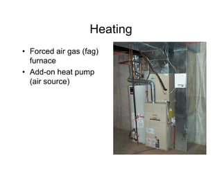
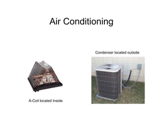
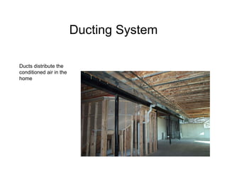
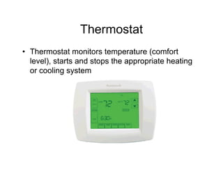
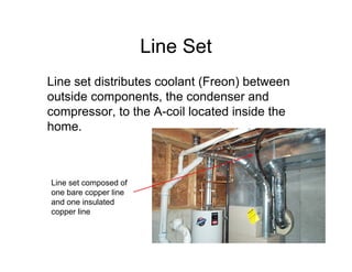
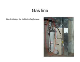
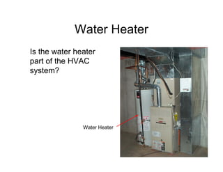
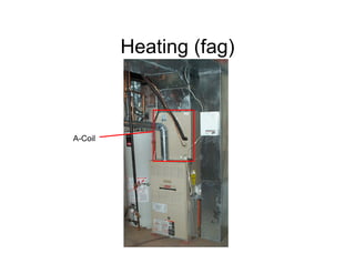
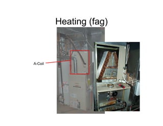
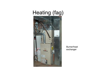
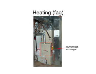
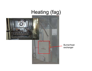
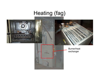
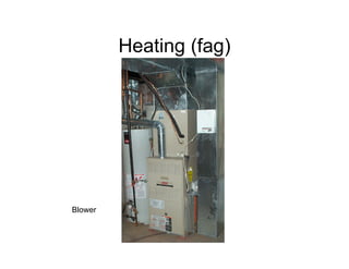
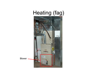
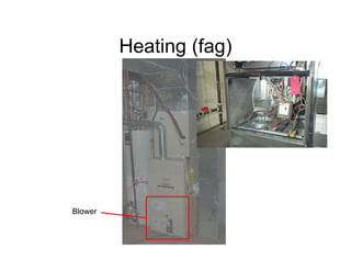
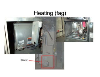
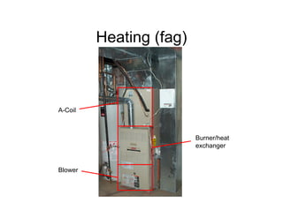
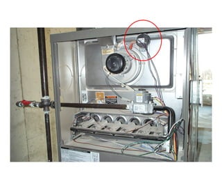
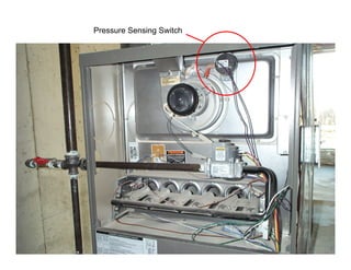
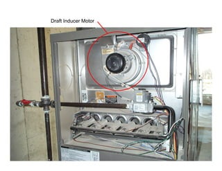
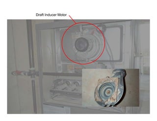
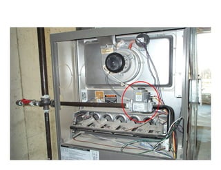
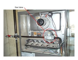
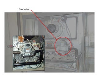
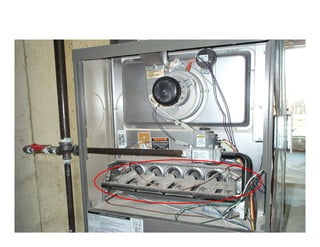
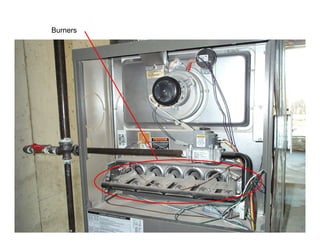
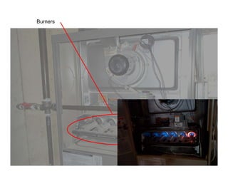
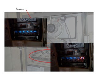
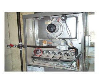
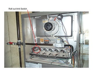
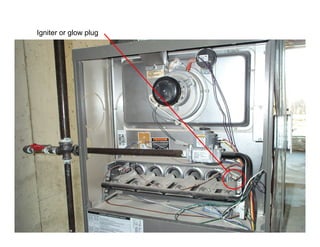
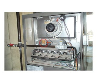
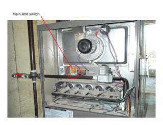
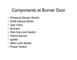
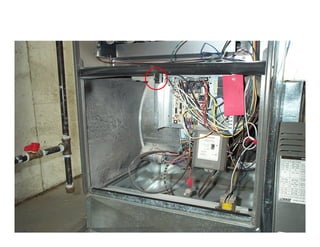
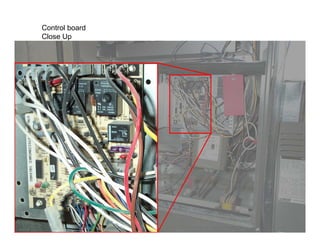
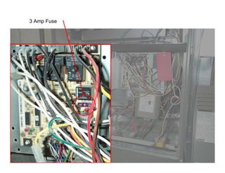
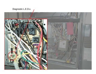
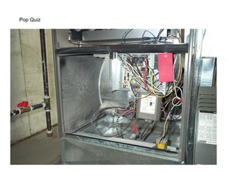
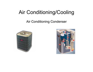
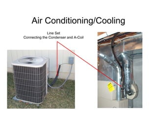
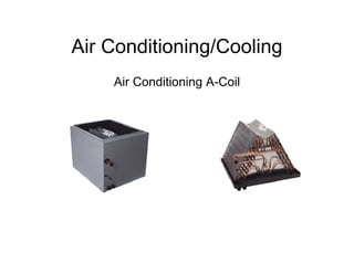
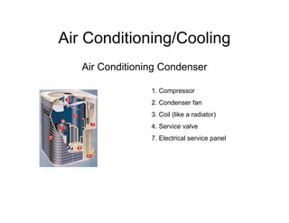
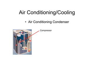
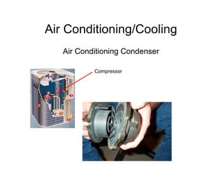
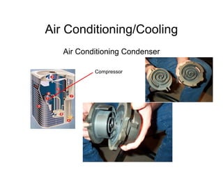
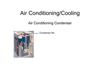
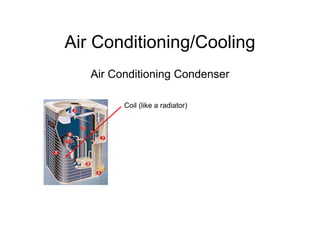
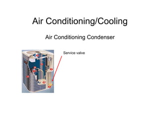
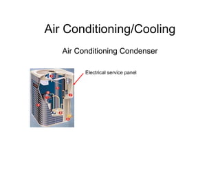
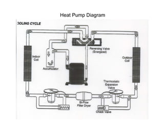
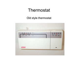
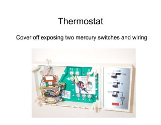
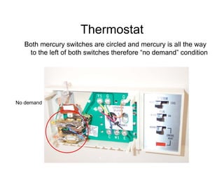
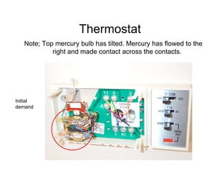
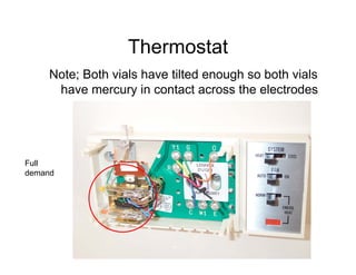
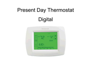
HVAC
Heating Ventilating & Air Conditioning
             By: Anthony D. Adams & Mark Gudde
                         March 2006


 This HVAC presentation is made up of two parts;

Part 1; Components of the system and what they do
Part 2; Diagnosing service issues, when to call in the
                     technician
HVAC
• Today we will show you;
• The major components of the HVAC
  system
• Smaller components of the system; what
  they are called and what they do
• Diagnostics that you can do and when to
  call the technician.
• There will be hand outs
Major Components
• The heating ventilation & air conditioning
  (HVAC) system is made up of many large
  components which are in turn made up of
  many smaller specialized components.
  First let’s see what the major components
  of the system are. We will later break each
  major component down into its individual,
  specialized components.
Heating
• Forced air gas (fag)
  furnace
• Add-on heat pump
  (air source)
Air Conditioning


                        Condenser located outside


A-Coil located Inside
Ducting System

Ducts distribute the
conditioned air in the
home
Thermostat
• Thermostat monitors temperature (comfort
  level), starts and stops the appropriate heating
  or cooling system
Line Set
Line set distributes coolant (Freon) between
outside components, the condenser and
compressor, to the A-coil located inside the
home.


Line set composed of
one bare copper line
and one insulated
copper line
Electricity
Electricity provides the Power to Operate
Fans, Compressors, Thermostats,
Computer Boards, Switches, and Sensors
required for the various systems to
operate.
Gas line
Gas line brings the fuel to the fag furnace
Water Heater
Is the water heater
part of the HVAC
system?


               Water Heater
Pop Quiz
What major components does it take to
provide the heating, ventilating, and air
conditioning for the homes we build?
Major system components
•   Heating (fag)
•   Cooling
•   Add-on heat pump (heating)
•   Ducting
•   Thermostat
•   Line set
•   Electricity
•   Gas line
Further Breakdown
• In this next section we will break down
  these major components into smaller parts
  and pieces and explain what role they play
  in making the system work.
Heating (fag)


A-Coil
Heating (fag)


A-Coil
Heating (fag)


A-Coil
Heating (fag)


                Burner/heat
                exchanger
Heating (fag)


                Burner/heat
                exchanger
Heating (fag)


                Burner/heat
                exchanger
Heating (fag)


                Burner/heat
                exchanger
Heating (fag)


Blower
Heating (fag)


Blower
Heating (fag)


Blower
Heating (fag)


Blower
Heating (fag)


A-Coil


                         Burner/heat
                         exchanger


Blower
Pressure Sensing Switch
Draft Inducer Motor
Draft Inducer Motor
Gas Valve
Gas Valve
Burners
Burners
Burners
Roll out limit Switch
Flame Sensor
Igniter or glow plug
Main limit switch
Power Switch
Pop Quiz
Components at Burner Door
•   Pressure Sensor Switch
•   Draft Inducer Motor
•   Gas Valve
•   Burners
•   Roll-Out-Limit Switch
•   Flame Sensor
•   Igniter
•   Main Limit Switch
•   Power Switch
Service Switch
Fresh air ventilation control
Control board
Control board
Close Up
3 Amp Fuse
Diagnostic L.E.D.s
Pop Quiz
Components at Blower Door
•   Service Switch
•   Fresh Air Ventilation Control
•   Control Board
•   3 Amp Fuse
•   Diagnostic L.E.D.s’
Air Conditioning/Cooling
   Air Conditioning Condenser
Air Conditioning/Cooling
              Line Set
Connecting the Condenser and A-Coil
Air Conditioning/Cooling
    Air Conditioning A-Coil
Air Conditioning/Cooling
   Air Conditioning Condenser

                 1. Compressor
                 2. Condenser fan
                 3. Coil (like a radiator)
                 4. Service valve
                 7. Electrical service panel
Air Conditioning/Cooling
  • Air Conditioning Condenser

           Compressor
Air Conditioning/Cooling
   Air Conditioning Condenser

           Compressor
Air Conditioning/Cooling
   Air Conditioning Condenser

           Compressor
Air Conditioning/Cooling
   Air Conditioning Condenser

         Condenser fan
Air Conditioning/Cooling
   Air Conditioning Condenser

         Coil (like a radiator)
Air Conditioning/Cooling
   Air Conditioning Condenser

         Service valve
Air Conditioning/Cooling
   Air Conditioning Condenser

         Electrical service panel
Capacitor


Outside
thermostat   Defrost control
             board


  Points
Air Conditioning/Cooling
   Air Conditioning Condenser

           Pop Quiz by the Numbers


           1. Compressor
           2. Condenser fan
           3. Coil (like a radiator)
           4. Service valve
           7. Electrical service panel
Add on Heat Pump
Some Terminology & How it Works
•   Reversing valve
•   High pressure line
•   Low pressure line
•   Freon, gas or liquid?
•   Heat is relative
Heat Pump Diagram
Heat Pump Diagram
Thermostat
Old style thermostat
Thermostat
Cover off exposing two mercury switches and wiring
Thermostat
   Both mercury switches are circled and mercury is all the way
    to the left of both switches therefore “no demand” condition


No demand
Thermostat
   Note; Top mercury bulb has tilted. Mercury has flowed to the
            right and made contact across the contacts.


Initial
demand
Thermostat
     Note; Both vials have tilted enough so both vials
      have mercury in contact across the electrodes


Full
demand
Present Day Thermostat
        Digital

HVAC Service Class