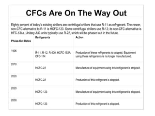
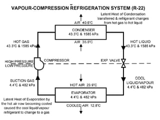
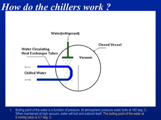
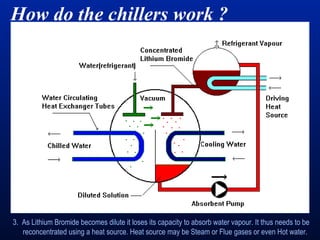
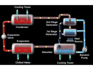
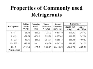
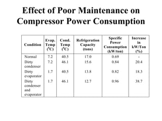
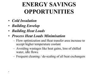
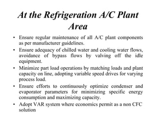
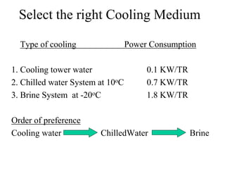
HVAC and Refrigeration System
Ton of refrigeration
The cooling effect produced is quantified as tons of
refrigeration.
1 ton of refrigeration = 3024 kCal/hr
heat rejected.
Conceptual view of a chilled-water
air-conditioning system
CFCs Are On The Way Out
Eighty percent of today’s existing chillers are centrifugal chillers that use R-11 as refrigerant. The newer,
non-CFC alternative to R-11 is HCFC-123. Some centrifugal chillers use R-12; its non-CFC alternative is
HFC-134a. Unitary A/C units typically use R-22, which will be phased out in the future.
Phase-Out Dates
Refrigerants Action
1996
R-11, R-12, R-500, HCFC-152A,
CFC-114
Production of these refrigerants is stopped. Equipment
using these refrigerants is no longer manufactured.
2010
HCFC-22 Manufacture of equipment using this refrigerant is stopped.
2020
HCFC-22 Production of this refrigerant is stopped.
2020
HCFC-123 Manufacture of equipment using this refrigerant is stopped.
2030
HCFC-123 Production of this refrigerant is stopped.
Introduction
Refrigeration deals with the transfer
of heat from a low temperature level
at the heat source to a high
temperature level at the heat sink.
– Air conditioning for comfort
– Refrigeration for process
Vapour compression System
How do the chillers work ?
1. Boiling point of the water is a function of pressure. At atmospheric pressure water boils at 100 deg. C.
When maintained at high vacuum, water will boil and subcool itself. The boiling point of the water at
6 mmHg (abs) is 3.7 deg. C.
How do the chillers work ?
2. Lithium Bromide (LiBr) has the property to absorb water due to its chemical affinity. At higher
concentration and lower temperature LiBr absorbs water vapour (refrigerant vapour) very effectively.
How do the chillers work ?
3. As Lithium Bromide becomes dilute it loses its capacity to absorb water vapour. It thus needs to be
reconcentrated using a heat source. Heat source may be Steam or Flue gases or even Hot water.
Vapour absorption chillers: Types
• Single effect steam fired (0.4 to 2 kg/cm2)
– Steam Consumption for 200 TR = 8.5 Kg/hr/TR
• Double effect steam fired (3 to 9 kg/cm2)
– Steam Consumption for 200 TR = 4.5 Kg/hr/TR
– Cost of m/c = Rs. 12000 to 15000 per TR
• Low temperature hot water fired (75 – 100oC)
• High temperature hot water fired (110 – 145oC)
• Direct fired (oil, gas, kerosene)
– HSD/LDO Consumption = 0.313 lit/hr/TR
– Kerosene Consumption =0.326lit/hr/TR
– Cost of m/c = Rs. 20,000 to 25000 per TR
Properties of Commonly used
Refrigerants
Enthalpy *
Refrigerant
Boiling
Point
** (o
C)
Freezing
Point
(o
C)
Vapor
Pressure
* (kPa)
Vapor
Volume *
(m3
/ Kg)
Liquid (kJ
/ Kg)
Vapor
(kJ / Kg)
R - 11 23.82 -111.0 25.73 0.61170 191.40 385.43
R - 12 -29.79 -158.0 219.28 0.07702 190.72 347.96
R - 22 -40.76 -160.0 354.74 0.06513 188.55 400.83
R - 502 -45.40 --- 414.30 0.04234 188.87 342.31
R - 7
(Ammonia)
-33.30 -77.7 289.93 0.41949 -808.71 487.76
COP = (H2-H1)/(H3-H2)
Performance Assessment
The specific power consumption kW/TR is a useful indicator of the
performance of refrigeration system. By messing refrigeration duty
performed in TR and the Kilo Watt inputs measured, kW/TR is
used as a reference energy performance indicator.
The refrigeration TR is assessed as TR = Q ⋅Cp ⋅ (Ti – To) / 3024
Where TR is cooling TR duty
Q is mass flow rate of coolant in kg/hr
Cp is coolant specific heat in kCal /kg / 0C
Ti is inlet. Temperature of coolant to evaporator (chiller) in 0C.
To is outlet temperature of coolant from evaporator (chiller) in 0C.
Overall energy consumption
• Compressor kW
• Chilled water pump kW
• Condenser water pump kW
• Cooling tower fan kW
Overall kW/TR = sum of all above kW/ TR
Effect of Variation in Evaporator
Temperature on
Compressor Power Consumption
Evaporator
Temperature
(0
C)
Refrigeration
Capacity
(tons)
Specific
Power
Consumption
Increase in
kW/ton (%)
5.0 67.58 0.81 -
0.0 56.07 0.94 16.0
-5.0 45.98 1.08 33.0
-10.0 37.20 1.25 54.0
-20.0 23.12 1.67 106.0
A 10C raise in evaporator temperature can help to save almost 3 % on power
consumption.
Effect of Variation in Condenser
Temperature on
Compressor Power Consumption
Condensing
Temperature
(0
C)
Refrigeration
Capacity
(tons)
Specific
Power
Consumption
Increase in
kW/TR
(%)
26.7 31.5 1.17 -
35.0 21.4 1.27 8.5
40.0 20.0 1.41 20.5
Effect of Poor Maintenance on
Compressor Power Consumption
Condition
Evap.
Temp
(0
C)
Cond.
Temp
(0
C)
Refrigeration
Capacity
(tons)
Specific
Power
Consumption
(kW/ton)
Increase
in
kW/Ton
(%)
Normal 7.2 40.5 17.0 0.69 -
Dirty
condenser
7.2 46.1 15.6 0.84 20.4
Dirty
evaporator
1.7 40.5 13.8 0.82 18.3
Dirty
condenser
and
evaporator
1.7 46.1 12.7 0.96 38.7
ENERGY SAVINGS
OPPORTUNITIES
• Cold Insulation
• Building Envelop
• Building Heat Loads
• Process Heat Loads Minimisation
– Flow optimization and Heat transfer area increase to
accept higher temperature coolant
– Avoiding wastages like heat gains, loss of chilled
water, idle flows
– Frequent cleaning / de-scaling of all heat exchangers
.
At the Refrigeration A/C Plant
Area
• Ensure regular maintenance of all A/C plant components
as per manufacturer guidelines.
• Ensure adequacy of chilled water and cooling water flows,
avoidance of bypass flows by valving off the idle
equipment.
• Minimize part load operations by matching loads and plant
capacity on line, adopting variable speed drives for varying
process load.
• Ensure efforts to continuously optimize condenser and
evaporator parameters for minimizing specific energy
consumption and maximizing capacity.
• Adopt VAR system where economics permit as a non CFC
solution
Select the right Cooling Medium
Type of cooling Power Consumption
1. Cooling tower water 0.1 KW/TR
2. Chilled water System at 10oC 0.7 KW/TR
3. Brine System at -20oC 1.8 KW/TR
Order of preference
Cooling water ChilledWater Brine
Energy Savings in Refrigeration systems
There are two broad ways by which energy
can be conserved
1.By decreasing the load
2.By optimising the refrigeration system
Calculating the operating load of a chiller plant
Refrigeration
plant
Refrigeration
plant
Hot well
12OC
Process
Cold well
8OC
Chilled water flow – 100 m3/hr
Refrigeration TR - 100,000 kg/hr x 1 x 4
3000
m Cp ∆Τ
- 133.33 TR
Power drawn by compressor, kW
Efficiency -
TR
120
- = 0.9
133.33
Energy saving measures in A/c System
• Comfort conditions: 25OC, 55 % RH
• Minimize heat load through glass windows
– Provide sun control film, Use double glass
• Insulate roof top in A/C Building
– Provide under deck insulation of 50 mm, Provide lawns at roof top
• Optimize fresh air supply into a/c room
– Conduct CO2 study to optimize fresh air quantity
– 10-15 cfm/person or 0.25 cfm/sq..ft as per ASHRAE
• Minimise artificial lighting
– Use natural lighting , 3.5 kw lighting consumes 1.0 TR load
• Provide controls
– install thermostat to control peak and base load
– Provide VSD for AHU with return air temp.sensor-set at 25oC
• Air tight the building envelop
– prevent cold air leakage, Provide door closures
• Avoid heat producing equipments inside the room
– keep away UPS Battery , ovens, other loads
Efficient operation & maintenance
• The suction Temperature, pressure delivery pressure of
compressors should be kept at optimum level
– Ensure all indicators are working properly
– Keep record of oil consumption
• Condensers
– Remove scale and algae and adopt suitable water treatment
– Give periodic purging of non-condensable gases
– Lesser the water temperature more the COP
– Routine defrosting of Cooling coils
– Stop condenser water pump when compressor not working
– 5OC rise in condensing temperature increases 10 % power
consumption
– 5OC rise in evaporating temperature increases 10 % power
consumption
Energy saving measures in refrigeration
• Look for process modifications to reduce the cooling load
• Use cooling water to remove the maximum heat before using chilled
water
• Provide VSD for condenser water pumps
– to vary the cooling water flow to maintain 4oC difference across the condensers
• Avoid primary pump operation
– Normally two pumps are operation(Chilled water supply pump from cold well
and return water pump from hot well)
– Modify to operate only return water pump
– Provide VSD for efficient part load operation
• Explore ‘Ice-bank’ system for Maximum demand reduction
• Explore application of vapour absorption with cost economics
• Replace old systems with modern energy efficient systems
Cold Insulation
Basis:
Ambient temperature - 35OC, emissivity – 0.8, still air conditions
Allowable heat ingress – 10 –15 Kcal/m2/hr
1915420
2711315
417310
86355
Exposed area per tonne
of refrigeration
Heat ingress
Kcal/m2/hr
Difference in temperature
between ambient and surface
• Thumb rules for cold Insulation
– Chilled water pipe insulation (Provide 2 to 3 inch thickness)
– Duct insulation (Provide 1 to 2 inch thickness)
– Suction line refrigerant pipe insulation(Provide 2 to3 inch thickness)

hvac and refrigeration system

  • 1.
  • 2.
    Ton of refrigeration Thecooling effect produced is quantified as tons of refrigeration. 1 ton of refrigeration = 3024 kCal/hr heat rejected.
  • 3.
    Conceptual view ofa chilled-water air-conditioning system
  • 4.
    CFCs Are OnThe Way Out Eighty percent of today’s existing chillers are centrifugal chillers that use R-11 as refrigerant. The newer, non-CFC alternative to R-11 is HCFC-123. Some centrifugal chillers use R-12; its non-CFC alternative is HFC-134a. Unitary A/C units typically use R-22, which will be phased out in the future. Phase-Out Dates Refrigerants Action 1996 R-11, R-12, R-500, HCFC-152A, CFC-114 Production of these refrigerants is stopped. Equipment using these refrigerants is no longer manufactured. 2010 HCFC-22 Manufacture of equipment using this refrigerant is stopped. 2020 HCFC-22 Production of this refrigerant is stopped. 2020 HCFC-123 Manufacture of equipment using this refrigerant is stopped. 2030 HCFC-123 Production of this refrigerant is stopped.
  • 5.
    Introduction Refrigeration deals withthe transfer of heat from a low temperature level at the heat source to a high temperature level at the heat sink. – Air conditioning for comfort – Refrigeration for process
  • 7.
  • 8.
    How do thechillers work ? 1. Boiling point of the water is a function of pressure. At atmospheric pressure water boils at 100 deg. C. When maintained at high vacuum, water will boil and subcool itself. The boiling point of the water at 6 mmHg (abs) is 3.7 deg. C.
  • 9.
    How do thechillers work ? 2. Lithium Bromide (LiBr) has the property to absorb water due to its chemical affinity. At higher concentration and lower temperature LiBr absorbs water vapour (refrigerant vapour) very effectively.
  • 10.
    How do thechillers work ? 3. As Lithium Bromide becomes dilute it loses its capacity to absorb water vapour. It thus needs to be reconcentrated using a heat source. Heat source may be Steam or Flue gases or even Hot water.
  • 13.
    Vapour absorption chillers:Types • Single effect steam fired (0.4 to 2 kg/cm2) – Steam Consumption for 200 TR = 8.5 Kg/hr/TR • Double effect steam fired (3 to 9 kg/cm2) – Steam Consumption for 200 TR = 4.5 Kg/hr/TR – Cost of m/c = Rs. 12000 to 15000 per TR • Low temperature hot water fired (75 – 100oC) • High temperature hot water fired (110 – 145oC) • Direct fired (oil, gas, kerosene) – HSD/LDO Consumption = 0.313 lit/hr/TR – Kerosene Consumption =0.326lit/hr/TR – Cost of m/c = Rs. 20,000 to 25000 per TR
  • 14.
    Properties of Commonlyused Refrigerants Enthalpy * Refrigerant Boiling Point ** (o C) Freezing Point (o C) Vapor Pressure * (kPa) Vapor Volume * (m3 / Kg) Liquid (kJ / Kg) Vapor (kJ / Kg) R - 11 23.82 -111.0 25.73 0.61170 191.40 385.43 R - 12 -29.79 -158.0 219.28 0.07702 190.72 347.96 R - 22 -40.76 -160.0 354.74 0.06513 188.55 400.83 R - 502 -45.40 --- 414.30 0.04234 188.87 342.31 R - 7 (Ammonia) -33.30 -77.7 289.93 0.41949 -808.71 487.76
  • 15.
  • 16.
    Performance Assessment The specificpower consumption kW/TR is a useful indicator of the performance of refrigeration system. By messing refrigeration duty performed in TR and the Kilo Watt inputs measured, kW/TR is used as a reference energy performance indicator. The refrigeration TR is assessed as TR = Q ⋅Cp ⋅ (Ti – To) / 3024 Where TR is cooling TR duty Q is mass flow rate of coolant in kg/hr Cp is coolant specific heat in kCal /kg / 0C Ti is inlet. Temperature of coolant to evaporator (chiller) in 0C. To is outlet temperature of coolant from evaporator (chiller) in 0C.
  • 17.
    Overall energy consumption •Compressor kW • Chilled water pump kW • Condenser water pump kW • Cooling tower fan kW Overall kW/TR = sum of all above kW/ TR
  • 18.
    Effect of Variationin Evaporator Temperature on Compressor Power Consumption Evaporator Temperature (0 C) Refrigeration Capacity (tons) Specific Power Consumption Increase in kW/ton (%) 5.0 67.58 0.81 - 0.0 56.07 0.94 16.0 -5.0 45.98 1.08 33.0 -10.0 37.20 1.25 54.0 -20.0 23.12 1.67 106.0 A 10C raise in evaporator temperature can help to save almost 3 % on power consumption.
  • 19.
    Effect of Variationin Condenser Temperature on Compressor Power Consumption Condensing Temperature (0 C) Refrigeration Capacity (tons) Specific Power Consumption Increase in kW/TR (%) 26.7 31.5 1.17 - 35.0 21.4 1.27 8.5 40.0 20.0 1.41 20.5
  • 20.
    Effect of PoorMaintenance on Compressor Power Consumption Condition Evap. Temp (0 C) Cond. Temp (0 C) Refrigeration Capacity (tons) Specific Power Consumption (kW/ton) Increase in kW/Ton (%) Normal 7.2 40.5 17.0 0.69 - Dirty condenser 7.2 46.1 15.6 0.84 20.4 Dirty evaporator 1.7 40.5 13.8 0.82 18.3 Dirty condenser and evaporator 1.7 46.1 12.7 0.96 38.7
  • 21.
    ENERGY SAVINGS OPPORTUNITIES • ColdInsulation • Building Envelop • Building Heat Loads • Process Heat Loads Minimisation – Flow optimization and Heat transfer area increase to accept higher temperature coolant – Avoiding wastages like heat gains, loss of chilled water, idle flows – Frequent cleaning / de-scaling of all heat exchangers .
  • 22.
    At the RefrigerationA/C Plant Area • Ensure regular maintenance of all A/C plant components as per manufacturer guidelines. • Ensure adequacy of chilled water and cooling water flows, avoidance of bypass flows by valving off the idle equipment. • Minimize part load operations by matching loads and plant capacity on line, adopting variable speed drives for varying process load. • Ensure efforts to continuously optimize condenser and evaporator parameters for minimizing specific energy consumption and maximizing capacity. • Adopt VAR system where economics permit as a non CFC solution
  • 23.
    Select the rightCooling Medium Type of cooling Power Consumption 1. Cooling tower water 0.1 KW/TR 2. Chilled water System at 10oC 0.7 KW/TR 3. Brine System at -20oC 1.8 KW/TR Order of preference Cooling water ChilledWater Brine
  • 24.
    Energy Savings inRefrigeration systems There are two broad ways by which energy can be conserved 1.By decreasing the load 2.By optimising the refrigeration system
  • 25.
    Calculating the operatingload of a chiller plant Refrigeration plant Refrigeration plant Hot well 12OC Process Cold well 8OC Chilled water flow – 100 m3/hr Refrigeration TR - 100,000 kg/hr x 1 x 4 3000 m Cp ∆Τ - 133.33 TR Power drawn by compressor, kW Efficiency - TR 120 - = 0.9 133.33
  • 26.
    Energy saving measuresin A/c System • Comfort conditions: 25OC, 55 % RH • Minimize heat load through glass windows – Provide sun control film, Use double glass • Insulate roof top in A/C Building – Provide under deck insulation of 50 mm, Provide lawns at roof top • Optimize fresh air supply into a/c room – Conduct CO2 study to optimize fresh air quantity – 10-15 cfm/person or 0.25 cfm/sq..ft as per ASHRAE • Minimise artificial lighting – Use natural lighting , 3.5 kw lighting consumes 1.0 TR load • Provide controls – install thermostat to control peak and base load – Provide VSD for AHU with return air temp.sensor-set at 25oC • Air tight the building envelop – prevent cold air leakage, Provide door closures • Avoid heat producing equipments inside the room – keep away UPS Battery , ovens, other loads
  • 27.
    Efficient operation &maintenance • The suction Temperature, pressure delivery pressure of compressors should be kept at optimum level – Ensure all indicators are working properly – Keep record of oil consumption • Condensers – Remove scale and algae and adopt suitable water treatment – Give periodic purging of non-condensable gases – Lesser the water temperature more the COP – Routine defrosting of Cooling coils – Stop condenser water pump when compressor not working – 5OC rise in condensing temperature increases 10 % power consumption – 5OC rise in evaporating temperature increases 10 % power consumption
  • 28.
    Energy saving measuresin refrigeration • Look for process modifications to reduce the cooling load • Use cooling water to remove the maximum heat before using chilled water • Provide VSD for condenser water pumps – to vary the cooling water flow to maintain 4oC difference across the condensers • Avoid primary pump operation – Normally two pumps are operation(Chilled water supply pump from cold well and return water pump from hot well) – Modify to operate only return water pump – Provide VSD for efficient part load operation • Explore ‘Ice-bank’ system for Maximum demand reduction • Explore application of vapour absorption with cost economics • Replace old systems with modern energy efficient systems
  • 29.
    Cold Insulation Basis: Ambient temperature- 35OC, emissivity – 0.8, still air conditions Allowable heat ingress – 10 –15 Kcal/m2/hr 1915420 2711315 417310 86355 Exposed area per tonne of refrigeration Heat ingress Kcal/m2/hr Difference in temperature between ambient and surface • Thumb rules for cold Insulation – Chilled water pipe insulation (Provide 2 to 3 inch thickness) – Duct insulation (Provide 1 to 2 inch thickness) – Suction line refrigerant pipe insulation(Provide 2 to3 inch thickness)