Downloaded 37 times


![Multi-FPGA Partitioning Alessandro Panella [email_address]](https://image.slidesharecdn.com/hpps-final-061420071146/85/HPPS-Final-06-14-2007-12-320.jpg)


![Project phases First Phase [15th March – 12th April] Documentation: presentation (12/4), report Goals: Analysis of the state of the art Produce some hints on a new approach Second Phase [13th April – 17th May] Documentation: presentation (17/5), report Goals: Precise definition of the problem Propose a new solution Third Phase [18th May – 14th June] Documentation: presentation (14/6), final report Goal Implementation and evaluation of the proposed solution](https://image.slidesharecdn.com/hpps-final-061420071146/85/HPPS-Final-06-14-2007-16-320.jpg)


![Chimera Multi-FPGAs Architecture Definition Matteo Murgida [email_address]](https://image.slidesharecdn.com/hpps-final-061420071146/85/HPPS-Final-06-14-2007-30-320.jpg)


![Development of an OS architecture-independent layer for dynamic reconfiguration Ivan Beretta [email_address]](https://image.slidesharecdn.com/hpps-final-061420071146/85/HPPS-Final-06-14-2007-47-320.jpg)


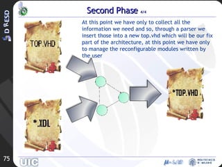
![Design FLow Antonio Piazzi [email_address]](https://image.slidesharecdn.com/hpps-final-061420071146/85/HPPS-Final-06-14-2007-64-320.jpg)


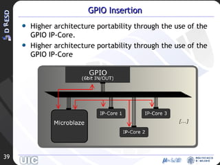
![Management of 2D Reconfiguration in a Reconfigurable System Massimo Morandi [email_address]](https://image.slidesharecdn.com/hpps-final-061420071146/85/HPPS-Final-06-14-2007-85-320.jpg)


![Relocation for 2D Reconfigurable Systems Marco Novati [email_address]](https://image.slidesharecdn.com/hpps-final-061420071146/85/HPPS-Final-06-14-2007-102-320.jpg)


This document summarizes the key aspects of a design flow framework that aims to simplify the development of partially reconfigurable systems. The framework hides complexity related to reconfiguration from designers and supports different architectural paradigms and communication infrastructures. It was developed in three phases: studying existing approaches, realizing the framework based on separated tools, and validating it with a new communication protocol. The framework generates architectures from a system description and allows designers to focus on writing modules while handling reconfiguration details.