Download to read offline
![Design Methodologies for Dynamic Reconfigurable Multi-FPGA Systems BY Alessandro Panella [email_address] 3-Day DRESD 07/28 – 08/01 2008 Hotel Villa Gina, Goglio, Italy](https://image.slidesharecdn.com/dreams-1218466617531174-9/75/3rd-3DDRESD-DReAMS-1-2048.jpg)


![Partial MFS design flows Address only some phases of the design Usually partitioning and placement Iterative approaches Genetic algorithm [Hidalgo et al., DSD ‘02] Simulated annealing [Roy at al., ICCAD ’93; Vicente et al., FPL ‘99] Hierarchical approaches Exploit the design hierarchy in partitioning Behrens et al., ICCAD ‘96 Hierarchy exploration heuristic Fang et al., TODAES ‘00 Hierarchy extraction from Verilog spec. Set-covering procedure](https://image.slidesharecdn.com/dreams-1218466617531174-9/75/3rd-3DDRESD-DReAMS-16-2048.jpg)
![Dynamic Reconfigurable MFS Extraction of a directed task graph from VHDL Task graph divided into time segments Using a non-linear programming model Each segment is spatially partitioned [ Ouaiss et al. , An Integrated Partitioning and Synthesis System for Dynamically Reconfigurable Multi-FPGA architectures, 1998] Dynamic?](https://image.slidesharecdn.com/dreams-1218466617531174-9/75/3rd-3DDRESD-DReAMS-17-2048.jpg)


![Annealing implementation Solution: array [c i ] , node i is placed in FPGA c i Cost: Weighted Estimated Wire Length (WEWL) Random move: single-node or swap, with equal probability Constraints: Area constraint I/O Pin constraint Handled with penalties](https://image.slidesharecdn.com/dreams-1218466617531174-9/75/3rd-3DDRESD-DReAMS-26-2048.jpg)
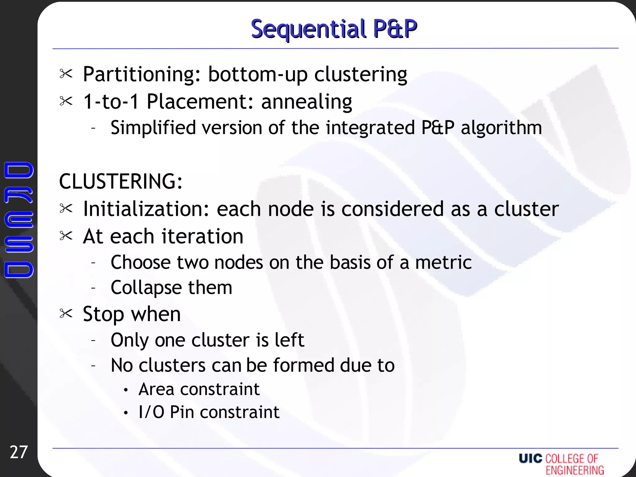


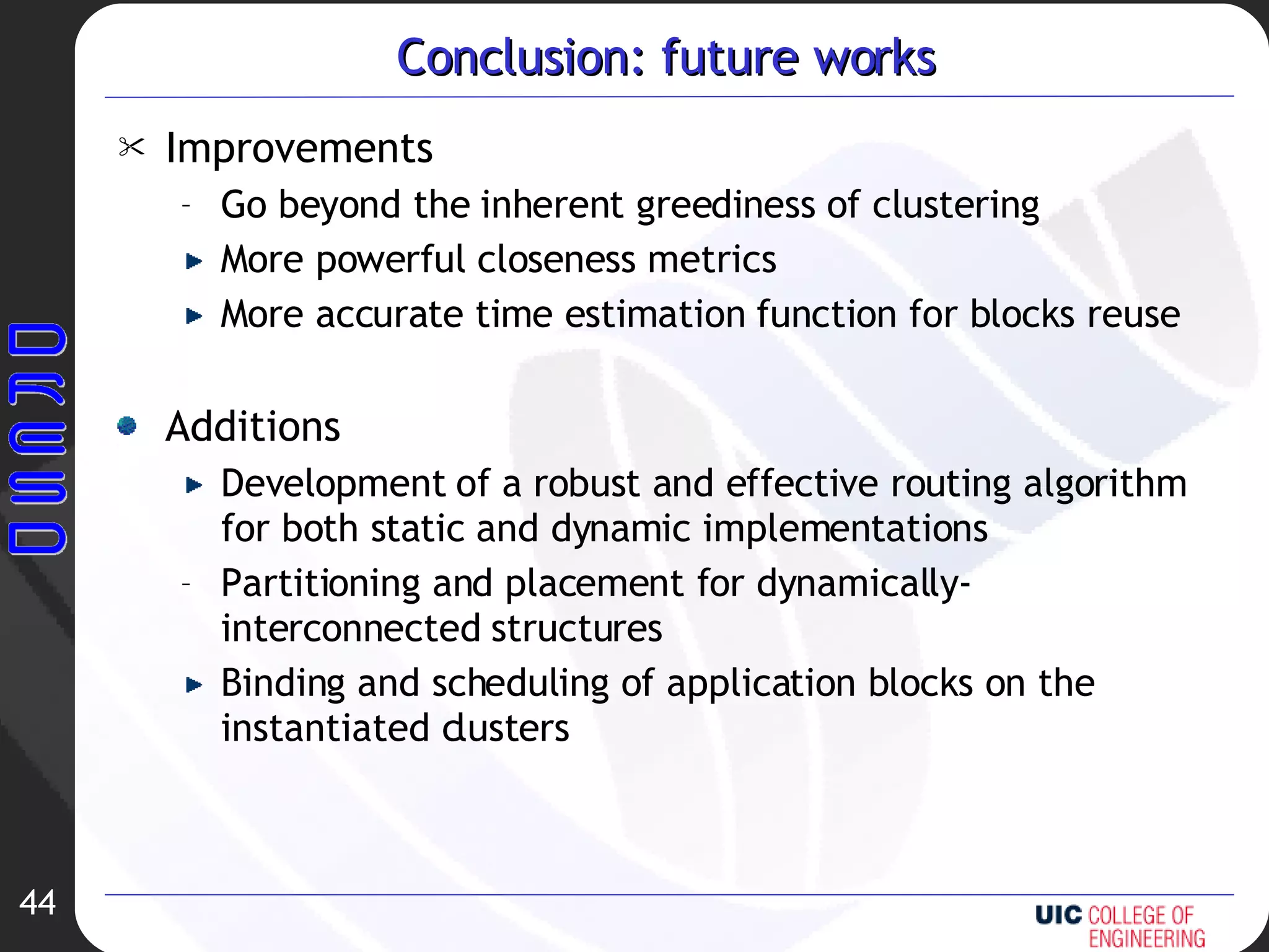


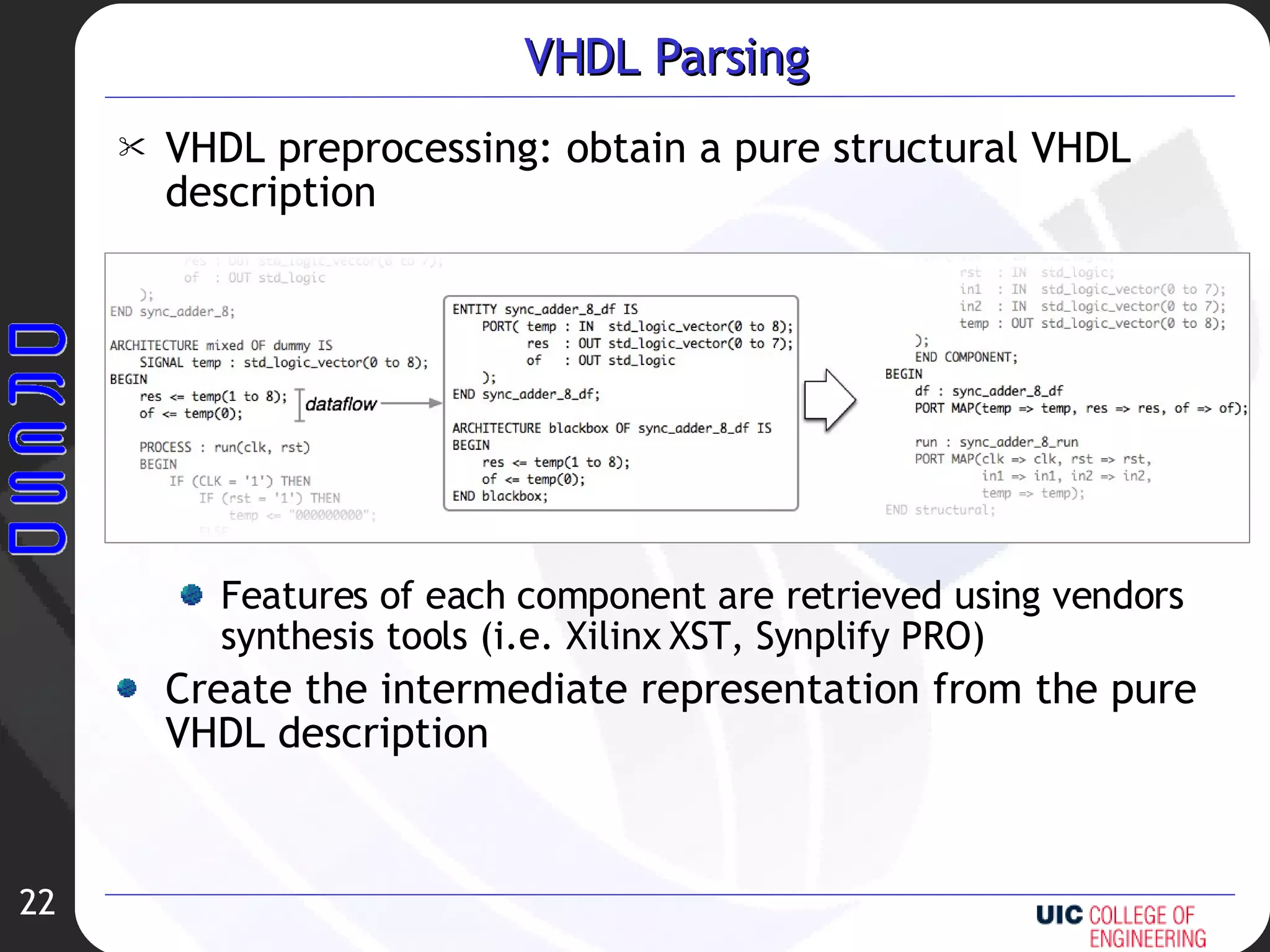
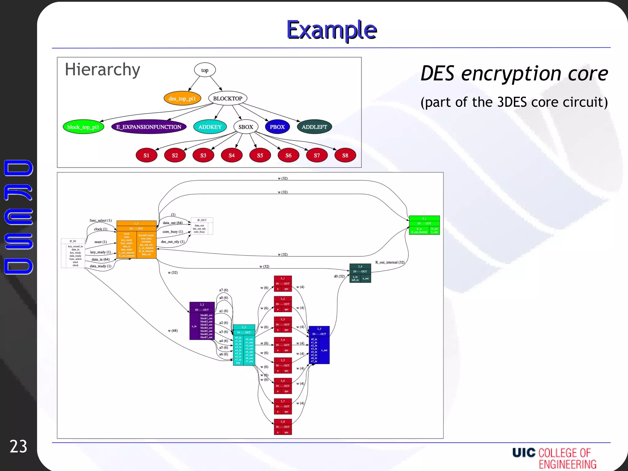
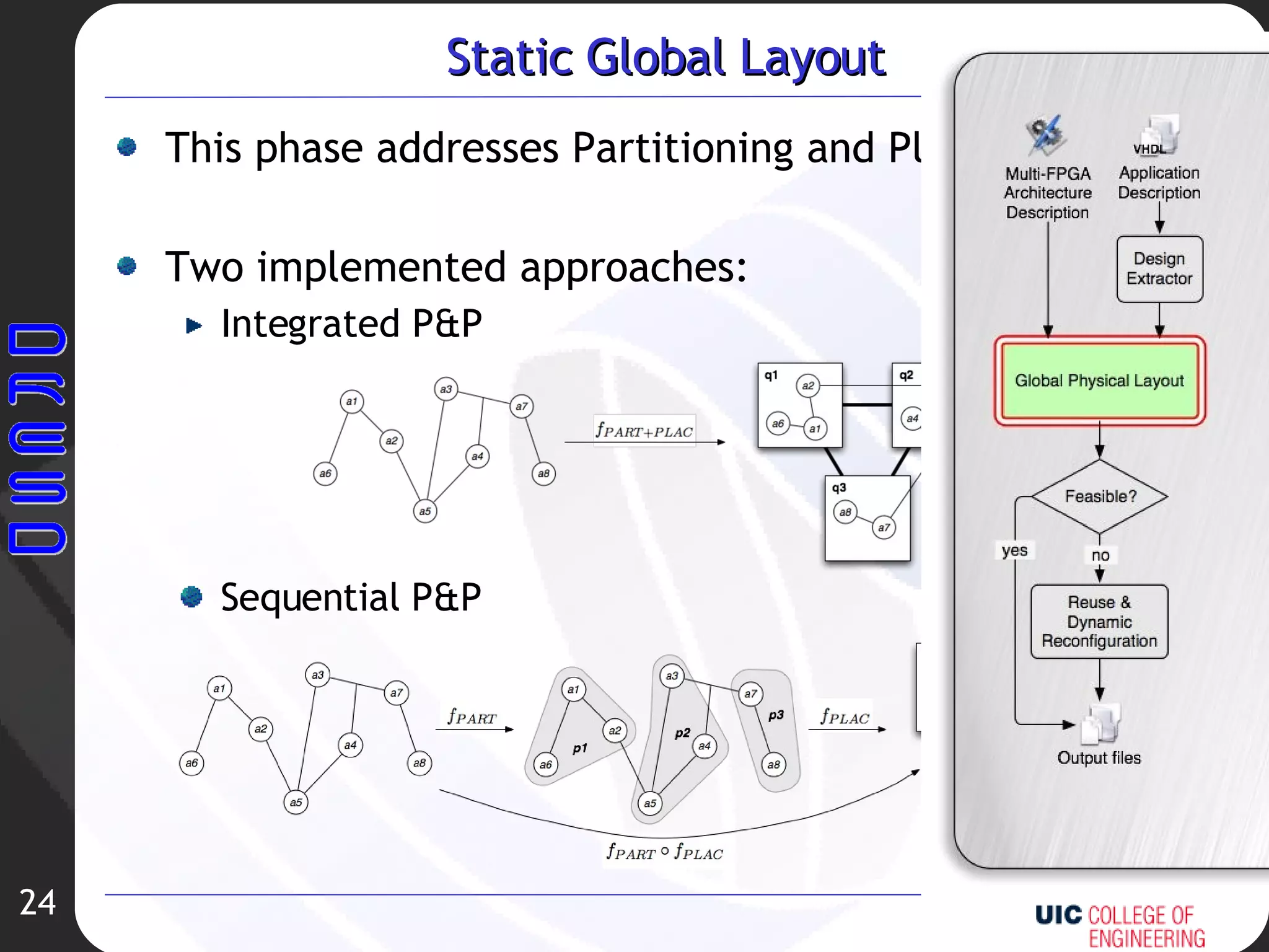
The document describes a methodology for designing dynamic reconfigurable multi-FPGA systems. It presents an intermediate representation for hierarchical circuits and a design flow with three main phases: design extraction from VHDL, static global layout partitioning and placement, and reuse through dynamic reconfiguration to minimize delays. Experimental results validate partitioning, placement and blocks reuse approaches. Future work includes improving clustering metrics, time estimation, and adding routing algorithms.