Downloaded 32 times

![Multi-FPGA Partitioning Alessandro Panella [email_address]](https://image.slidesharecdn.com/rev2-hpps-project-2007-22039/85/Rev2-HPPS-Project-2007-6-320.jpg)
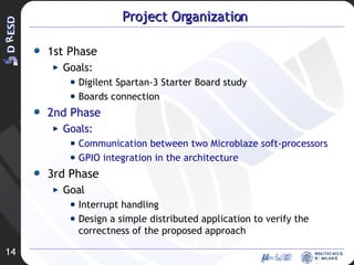
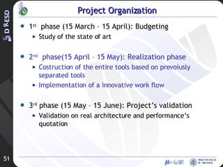
![Project Organization First Phase (15 Mar- 15 Apr) [DONE] Goals State of the art analysis Proposed approach: basic idea Second Phase (15 Apr – 15 May) [PARTIALLY DONE] Goal Partitioning algorithm: development and implementation Third Phase (15 May – 15 June) [TODO] Goal Algorithm experimental evaluation Physical evaluation using the DReAMS architecture](https://image.slidesharecdn.com/rev2-hpps-project-2007-22039/85/Rev2-HPPS-Project-2007-7-320.jpg)
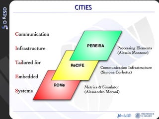
![Chimera Multi-FPGAs Architecture Definition Matteo Murgida [email_address]](https://image.slidesharecdn.com/rev2-hpps-project-2007-22039/85/Rev2-HPPS-Project-2007-13-320.jpg)

![P rocessing E lements RE configuration I n R econfigurable A rchitectures Alessio Montone [email_address]](https://image.slidesharecdn.com/rev2-hpps-project-2007-22039/85/Rev2-HPPS-Project-2007-21-320.jpg)
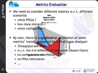
![R econfiguration O riented Me trics Alessandro Meroni [email_address]](https://image.slidesharecdn.com/rev2-hpps-project-2007-22039/85/Rev2-HPPS-Project-2007-28-320.jpg)
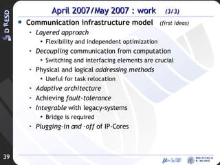
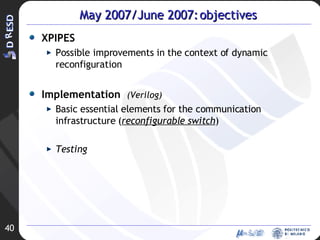
![RE configurable C ommunication I nfrastructure F or E mbedded-systems Simone Corbetta [email_address]](https://image.slidesharecdn.com/rev2-hpps-project-2007-22039/85/Rev2-HPPS-Project-2007-35-320.jpg)
![Development of an OS architecture-independent layer for dynamic reconfiguration Ivan Beretta [email_address]](https://image.slidesharecdn.com/rev2-hpps-project-2007-22039/85/Rev2-HPPS-Project-2007-43-320.jpg)
![Design FLow Antonio Piazzi [email_address]](https://image.slidesharecdn.com/rev2-hpps-project-2007-22039/85/Rev2-HPPS-Project-2007-50-320.jpg)

![Effects of 2D Reconfiguration in a Reconfigurable System Massimo Morandi [email_address]](https://image.slidesharecdn.com/rev2-hpps-project-2007-22039/85/Rev2-HPPS-Project-2007-59-320.jpg)

![Relocation for 2D Reconfigurable Systems Marco Novati [email_address]](https://image.slidesharecdn.com/rev2-hpps-project-2007-22039/85/Rev2-HPPS-Project-2007-66-320.jpg)
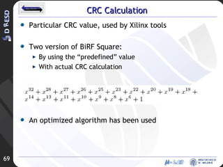
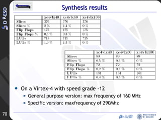
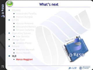
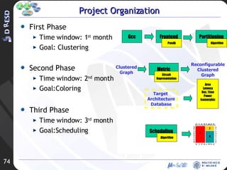
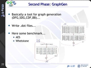

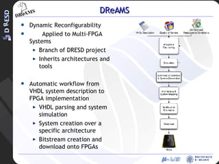
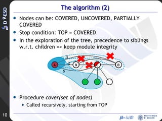
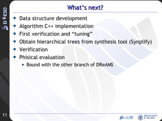
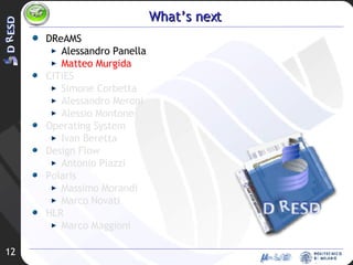
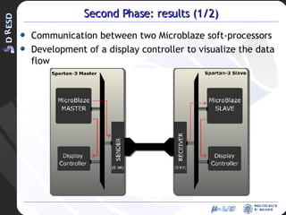
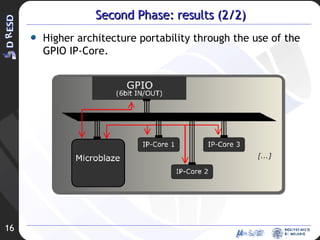
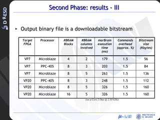
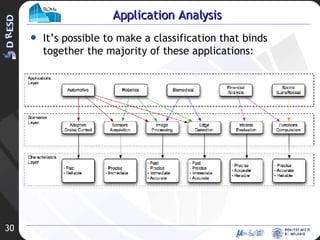
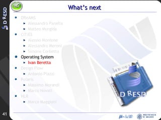
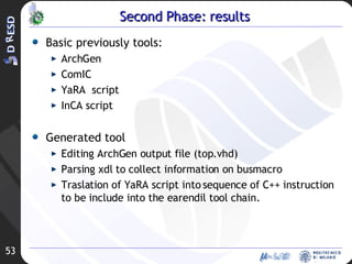
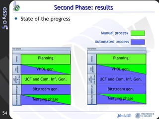
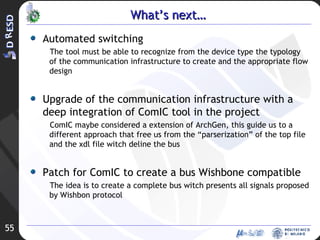
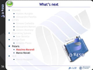
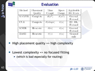
This document summarizes several projects related to high performance processors and systems. It outlines projects on dynamic reconfigurability applied to multi-FPGA systems (DReAMS), a chimera multi-FPGA architecture (CITiES), reconfiguration-oriented metrics, a reconfigurable communication infrastructure for embedded systems, and operating system support for reconfigurable SoCs. It provides updates on the objectives and results of the second phases of each project.