
Downloaded 964 times

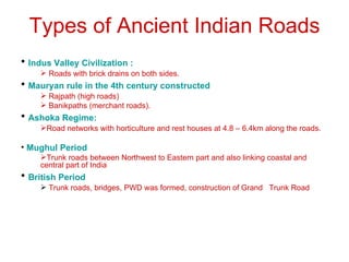

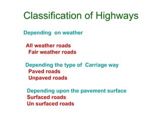
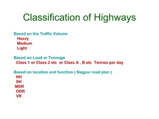
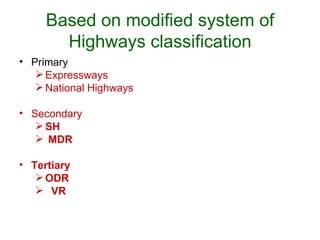


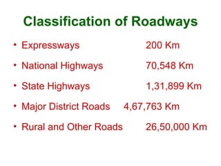


This document discusses highway planning and alignment in India. It provides a brief history of road development in India from ancient times to the present. It then covers the classification of highways in India based on factors like traffic volume and location. The document also outlines the major institutions involved in highway planning, design, and implementation at different government levels. Finally, it discusses the key factors that influence highway alignment, such as obligatory points, traffic needs, geometry, economics, and terrain considerations.


