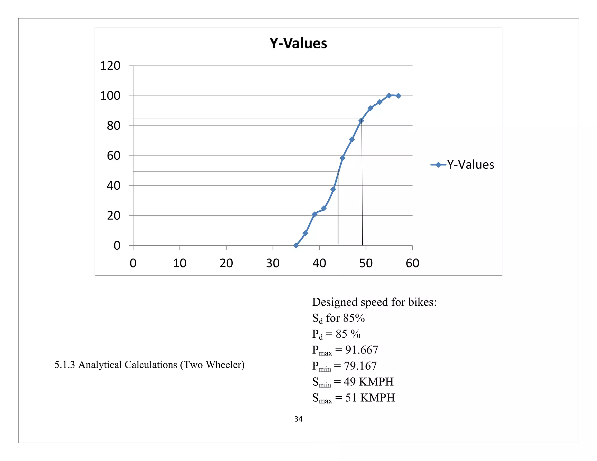
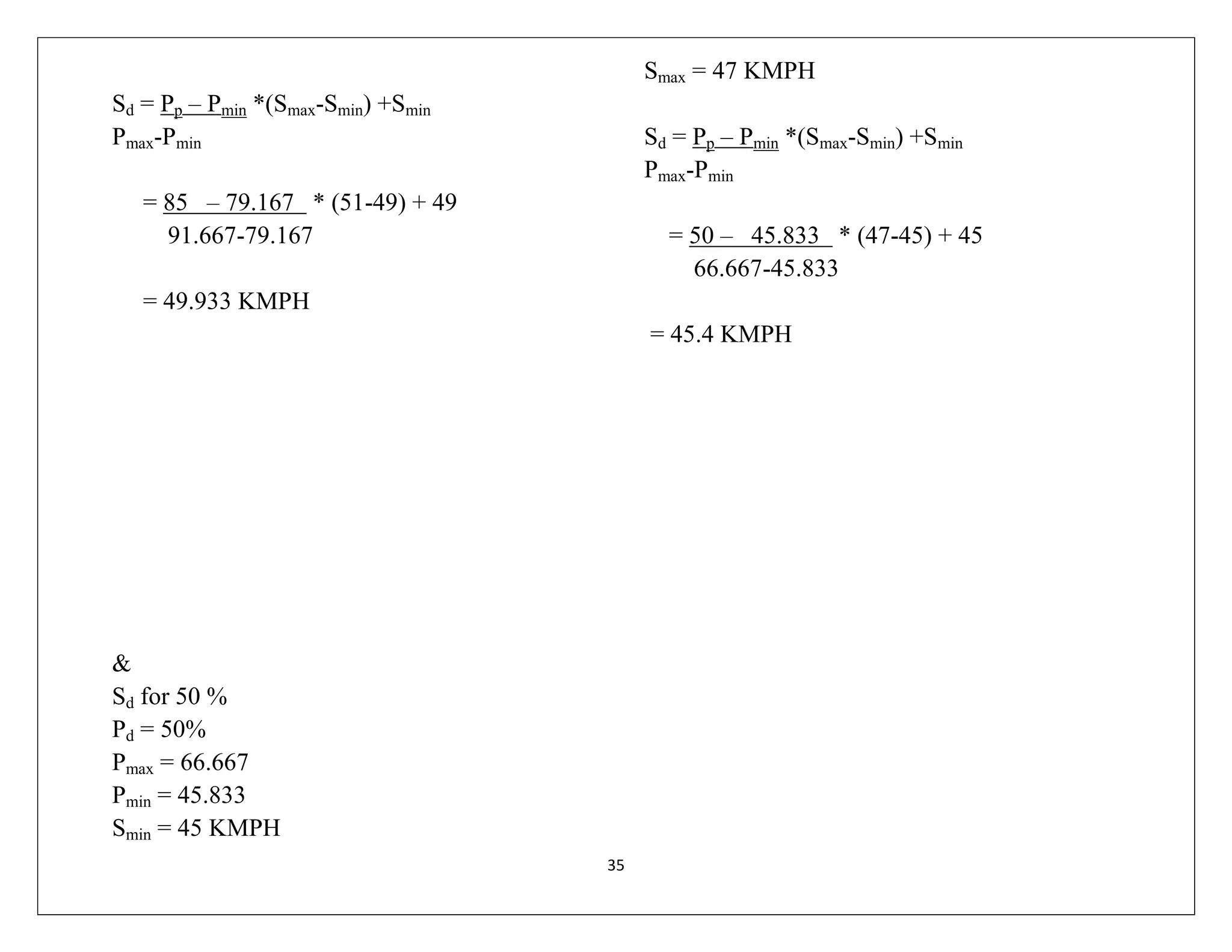
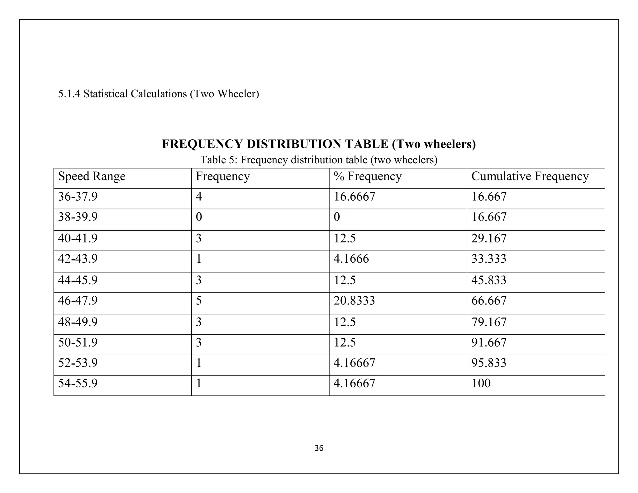
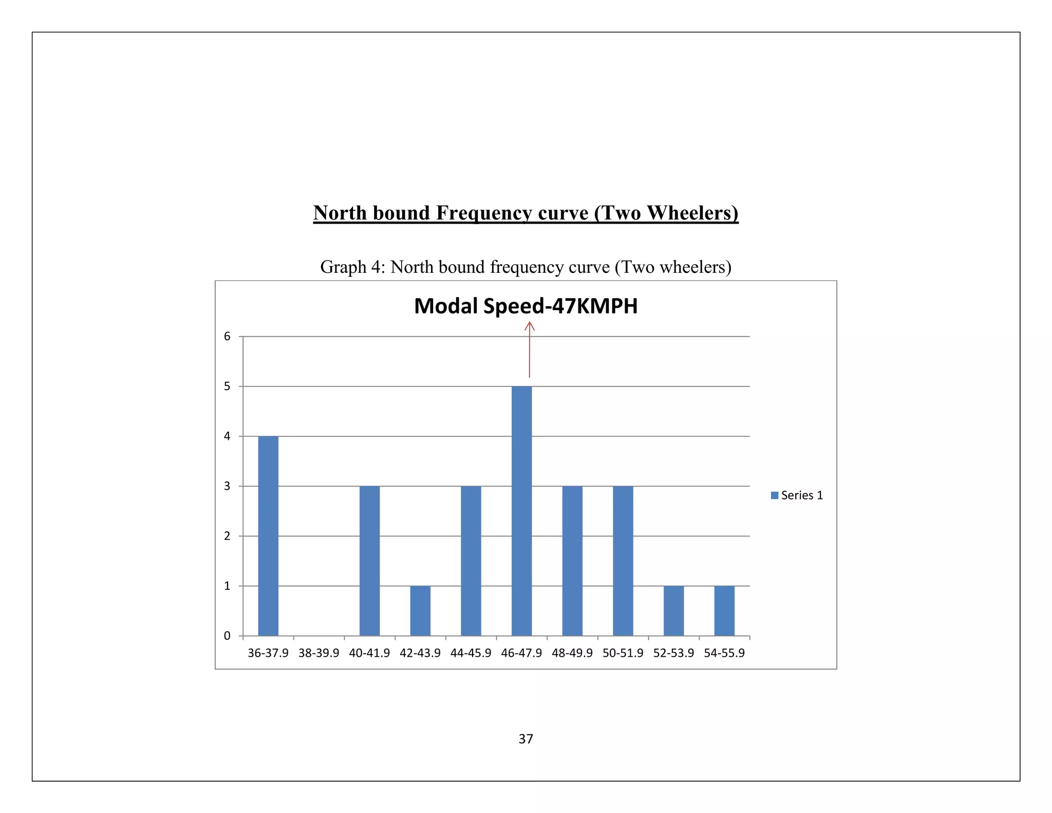
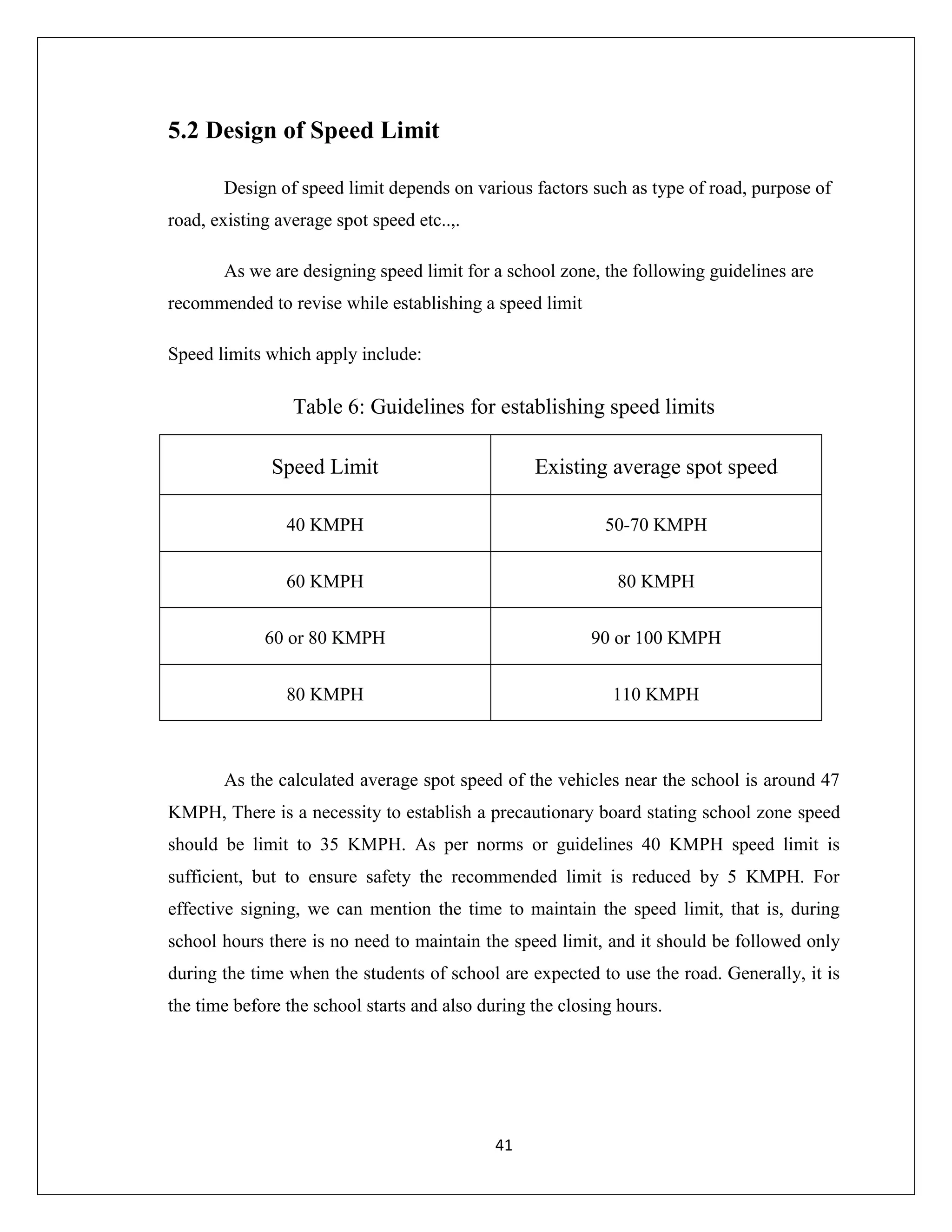
SlideShare a Scribd company logo
1
A Mini-Project report on
SPOT SPEED AND SPEED DELAY TIME SURVEY
BACHELOR OF TECHNOLOGY
IN
CIVIL ENGINEERING
Submitted By
Ch Venu 12245A0107
Y Sai Santosh 11241A01C0
M Vinod Kumar 11241A0152
Y Hemanth Reddy 11241A0160
B Naveen Reddy 11241A0167
Under the Guidance of
Sri V Srinivasa Reddy
Associative Professor
DEPARTMENT OF CIVIL ENGINEERING
GOKARAJU RANGARAJU INSTITUTE OF ENGINEERING AND
TECHNOLOGY- AUTONOMOUS
(Approved by AICTE Affiliated to JNTUH- NBA Accredited)
BACHUPALLY, KUKATPALLY HYDERABAD-500090
2014
2
Acknowledgement
The satisfaction and euphoria that accompany the successful completion of any
task would be incomplete without the mention of people who made it possible. We wish
to express our deep sense of gratitude towards our Internal Guide Sri V Srinivasa
Reddy, Associative Professor, Civil Engineering, for giving us an opportunity to work
on this project that was very interesting for us.
We would also like to express our deepest sense of gratitude towards Sri V
Gajendra, Associative Professor, Civil Engineering, for helping us to complete our
project successfully.
We would like to place on record my deep sense of gratitude to Dr Mohammed
Hussain, Head of the Department, Civil Engineering for his generous guidance, help
and useful suggestions.
We express a whole hearted gratitude to Dr Jandhyala N Murthy, Principal of
Gokaraju Rangaraju Institute of Engineering and Technology, for providing us the
conductive environment for carrying through our academic schedules and project with
ease.
We are grateful to the staff of our college for providing facilities for completion
of the project. We acknowledge the help of all those who had given encouragement and
associate themselves in one way or the other in completion of the dissertation work.
3
CONTENTS
Abstract
List of Figures
List of Tables
List of Graphs
1. Introduction 01-06
1.1 Spot Speed studies 01
1.1.1 Motivation 01
1.1.2 Problem Definition 02
1.1.3 Objectives of spot speed studies 02
1.1.4 Limitations of spot speed studies 02
1.2 Speed Delay Time Survey 03
1.2.1 Motivation 03
1.2.2 Problem Definition 03
1.2.3 Objectives of speed delay time survey 03
1.2.4 Limitations of speed delay time survey 04
1.3 Break Down Structure 05
1.3.1 BDS of Spot Speed Studies 05
1.3.2 BDS of Speed Delay Time Survey 06
2. Literature Survey 07-10
2.1 Introduction 07
2.2 Spot Speed Studies 07
2.2.1 Existing System 07
2.2.2 Disadvantages of Existing system 08
2.2.3 Proposed System 09
2.3 Speed Delay Time Survey 09
2.3.1 Existing System 09
2.3.2 Disadvantages of Existing system 10
2.3.3 Proposed System 10
3. Spot Speed Methodology 11-16
3.1 Introduction 11
3.2 Methods of Spot Speed Measurement 12
3.2.1 Stop Watch Method 13
3.2.2 Pneumatic Tube Method 14
4
3.2.3 Doppler-Principle Meter 15
3.2.4 Electronic-Principle Detectors 16
4. Stop Watch Method 17-21
4.1 Stretch Selection Criteria 17
4.2 Experimentation 18
4.3 Data collection 20
5. Calculations and Design 22-34
5.1 Calculations 22
5.1.1 Analytical Calculations(Four Wheeler) 22
5.1.2 Statistical Calculations(Four Wheeler) 23
5.1.3 Analytical Calculations(Two Wheeler) 27
5.1.4 Statistical Calculations(Two Wheeler) 28
5.2 Design of Speed Limit 32
5.3 Recommendations 33
6. Speed and Delay Time Survey 34-37
6.1 Introduction 34
6.2 Methods of Speed Delay Time Survey 34
6.2.1 Floating Car Method 35
6.2.2 License Plate Method 36
6.2.3 Interview Technique 37
6.2.4 Elevated Observer Method 37
7. Floating Car Methodology 38-40
7.1 Stretch Selection Criteria 38
7.2 Experimentation 38
7.3 Data Collection 40
8. Speed Delay Time Survey Calculations 41-42
9. Discussions and conclusions 43
5
Abstract
Designing and construction of a road involves estimation of traffic volume and
setting up ideal speed for the vehicles to travel in a comfortable way. Now days, due to
rapid increase in volume of traffic the designed speed on high ways could not be
maintained resulting a delay in reaching target point.
Our project also involves survey of spot speed of vehicles near a school zone.
This helps us to recommend changes to the existing system. These recommendations may
involve establishment of precautionary sighs like school zone, speed limit etc.
Our project is to study the traffic volume and check the time to reach the target in
off-peak and peak timings on a high way stretch (say from JNTU to Lingampally) and
coming up with both analytical and practical solution under IRC guidelines. The
conclusion of the project is the solution to problems faced inNH-9 journey by checking
personally and taking feedback of public using the highway.
6
List of Figures
1. Spot speed survey BDS 05
2. Speed delay time survey BDS 06
3. ZENAS International School 08
4. Pictorial representation of stop watch method 13
5. Pneumatic road tube method 14
6. RADAR method 15
7. Photography method 16
8. First and Third observer recording the time of travel 19
9. Second observer signaling that the test vehicle crossed the section 19
10. School zone board 33
11. Map showing starting and destination points-speed delay time survey 39
List of Tables
1. Guideline for selecting stretch length 18
2. Spot speed observations(Four wheelers) 20
3. Spot speed observations(Two wheelers) 21
4. Frequency distribution(Four wheelers) 23
5. Frequency distribution(Two wheelers) 28
6. Guidelines for establishing speed limits 32
7. Speed delay time survey observations 40
List of Graphs
1. North bound frequency curve(Four wheelers) 24
2. Frequency distribution curve(Four wheelers) 25
3. Cumulative frequency curve(Four wheelers) 26
4. North bound frequency curve(Two wheelers) 29
5. Frequency distribution curve(Two wheelers) 30
7
6. Cumulative frequency curve(Two wheelers) 31
Chapter-1
INTRODUCTION
Traffic Engineering is that branch of engineering which deals with the
improvement of traffic performance of road networks and terminals. This is achieved by
systematic traffic studies, scientific analysis and engineering applications. Traffic
engineering deals with the application of scientific principles, tools, techniques and
findings for safe, rapid, convenient and economic moment of people and goods. The
basic object of traffic engineering is to achieve efficient free and rapid flow of traffic
with least number of traffic accidents. Factual studies of traffic operations provide the
foundation for developing methods for improvement in general and for solving specific
problems. These studies help in deciding the geometric design feature and traffic control
for safe and efficient traffic moments.
Speed is an important transportation consideration because it relates to safety,
time, comfort, convenience and economics. The actual speed of vehicles over a particular
route may fluctuate widely depending on several factors such as geometric features,
traffic conditions, time, place, environment and driver.
1.1 Spot speed studies
1.1.1 Motivation
The profession of traffic engineering as known today has evolved with the advent
of motor vehicles. During the last few decades significant advances have been made in
many phases of the profession. Advance study and training facilities have been made
available at several universities and institutions. Traffic engineering has now been
recognized as an essential tool in the improvement of traffic operations in metropolitan
cities like Bombay, Calcutta, and Madras. Study of speed characteristics is the most
essential perquisite for any improvement of traffic facilities.
8
1.1.2 Problem Definition
In present scenario due to heavy traffic volume, the existing roads are insufficient
to maintain the design speed. With the help of spot speed studies we can manage the
traffic volume by diversion or by designing signal cycle time.
1.1.3 Objectives of Spot Speed Study
Spot speed survey is conducted to
i) To establish speed limit in a school zone near Zenus International School, Hydernagar.
ii) To recommend Zebra crossing or pedestrian signal if necessary.
iii) To recommend caution signs in the school zone
iv) To compare diverse types of drivers and vehicles under specified conditions
1.1.4 Limitations of the study
• The spot speeds are affected by physical features of the road like Pavement width,
curve sight distance, gradient, Pavement unevenness, intersections, and road side
developments.
• Other factors affecting spot speeds are environmental conditions, enforcement,
traffic conditions, driver, vehicle and motive of travel.
• The greatest disadvantage is that the progress is as slow as it is difficult to spot
out typical vehicles and number of vehicles observed will be less.
9
• There is a possibility of human error.
1.2 Speed delay time survey
1.2.1 Motivation
Due to the fact that delay at signalized intersections is of particular interest, many
efforts are put on the intersection delay study. Accurate estimation of delays has many
implications in traffic engineering studies. Transportation planners will use delay to
evaluate economic loses, whereas traffic engineers will use delays to determine level of
service at signalized intersections. In general the methodology used in analyzing
intersection delay comes from the HCM (Highway Capacity Manual).
1.2.2 Problem Definition
Due to congested roads at peak hours, Public faces speeding problems, this may
also lead because of traffic jams, accidents, bad traffic management etc.., Travel time
plays key role in city’s life and it indicates the level of service of roadway network
performance. From mobility point of view travel time reflects degree of convenience
from one point to the other point.
1.2.3 Objectives of Speed Delay Time Survey
• To determine running speed, overall speed, Fluctuation in speed and to find out
delay time between two stations of a road spaces apart.
• To gather the information such as amount, location, duration frequency and the
causes of the delay in the traffic stream.
10
• To determine the spots of congestion and causes and in-arriving at a suitable
remedial measures.
• To find the travel time, average journey time, and benefit-cost analysis.
• To rate the efficiency of a road.
1.2.4 Limitations of Speed Time Delay Survey
• This survey requires more man power
• There is a possibility of human error
• For accurate results more number of experimental trips may be carried out
• Data collected may not show the complete features of the road and may not be
accurate because of fluctuating traffic flow time-time
11
1.3 Break Down Structure
1.3.1 Spot Speed Studies BDS
12
Fig 1: spot speed survey BDS
1.3.2 Speed Delay Time Survey
Fig 2: speed delay time survey BDS
Determine study parameters
Collection of Data
Analyses of Data
Experimentation
Calculations
Discussions &
recommendations
13
Chapter 2
Literature Survey
2.1 Introduction
The idea of doing this project is because of the traffic problem that every metro
Politian city is facing today in India. Our team decided to take up one problem in the city
and find out a solution that is feasible, economic, and easily adoptable. The one problem
that we can think of while was traffic jams that consume heavy time. Causes for the
traffic jam may be in-adequate roads, heavy traffic volume, in-efficient signal system,
bad traffic management, etc..,. School premises comes under a separate speed zones,
many precautions need to be taken near a school like establishing speed limit, and
precautionary zone, zebra crossing, and providing pedestrian signal if necessary.
Our study may be divided into two parts, one is determining spot speed of
vehicles near a school zone and to recommend changes to the existing system if
necessary and the other is to conduct speed delay time survey over a stretch, study all
features of the stretch and recommend necessary changes that can be adopted to solve the
delay problem.
2.2 Spot Speed Studies
2.2.1 Existing System
As a part of establishing speed zone in a school premises, we choose a school
located at Hydernagar directly connected to NH 9. We observed that the school does not
have any speed limit or a zebra crossing, so we decided to conduct a spot speed survey
near the school premises.
14
Coming to the features of the stretch, it is located on NH-9 road between
Hydernagar and Miyapur X roads. ZENAS International School is exactly located
between LISMP 3 and 1 HMR pillars.
Fig 3: ZENAS International School-aerial view
2.2.2 Disadvantages of Existing System
The school is directly connected to National Highway. Vehicles travel at very
high speed on a highway which may range from 60-80 KMPH. This is an example for
bad indication or bad signaling. There are no precautionary signs like school zone or
speed limit or zebra crossing. The high speed vehicles sometimes may not notice the road
crossing public, leading to accidents. To improvise the existing system, survey need to be
conducted
15
2.2.3 Proposed System
The proposed system or mechanism will overcome the disadvantages of existing
system. Firstly various study aspects are noticed, required primary data is collected, and
the collected is analyzed. Then the experimentation is done keeping all the study aspects
in mind. The experimentation results are analyzed and an appropriate solution is
recommended to the existing system. In this case, the recommendation may be on traffic
signaling or establishing speed limits.
2.3 Speed Delay Time Survey
2.3.1 Existing System
We considered a stretch of 8.4 KM that is from JNTU to Lingampally circle. The
features of this road are
 3 line road on both the sides.
 Tar bitumen road.
 As it is a National Highway passing through one of the major business
centers of the city, Heavy traffic is observed.
 All kinds of vehicles like Buses, Cars, Bikes, Lorries, and Autos use the
road.
 Six traffic signals should be crossed to reach the destination, among which
three have free left facility.
 Peak hours – 08:00 AM to 10:00 AM & 05:00 PM to 08:00 PM.
Due to high traffic volume, a part of the stretch from JNTU to Nizampet faces
severe traffic jam during peak hours and Miyapur X road junction passengers faces long
stop time due insufficient roads.
16
2.3.2 Disadvantages of Existing System
The three lane road is insufficient for the traffic during peak hours near JNTU,
Lingampally, Nizampet, Miyapur, and at Chandanagar. Some passengers violate the
rules; this may lead to traffic inconvenience. At some places the road is damaged and not
well maintained, this may lead to reduction in average traffic flow velocity. HMR works
are going on along the stretch length; this is causing inconvenience to the travelers. Due
to underground electricity wiring works, about 1.7mts of road width is been dug and let
open by the electricity department in the direction of JNTU to Nizampet, this is reducing
the available road width and sometimes may be dangerous during nights.
2.3.3 Proposed system
After conducting speed and delay time survey, some changes to the existing
system will be proposed after calculations and conclusions. The proposed system will
rectify the faults in present system like diverting the traffic as long as the metro work is
under progress. We will also propose changes keeping the future development of the
system in all aspects like- within a year metro transportation will be started and may
reduce the road usage to some extent. Just seeing the present situation proposing a road
extension because of a slight higher traffic volume is merely waste of funds. After
completion of metro and electricity board works, more road space will be available which
may be sufficient to manage the present traffic, so temporary recommendations will be
proposed considering the present situation.
17
Chapter 3
Spot Speed Methodology
3.1 Introduction
Speed is an important measure of the quality of travel and safety of road network.
Speed by definition is the rate of movement of vehicle in distance per unit time. A typical
unit of speed is kilometers per hour (KMPH) or miles per hour (mph).
The main purpose of this study is to determine traffic parameter, specially speed. Spot
Speed measurements are most often taken at a point (or a short section) of road way
under conditions of free flow.
The intent is to determine the speeds that drivers select, unaffected by the existence of
congestion. This information is used to determine general speed trends, to help determine
reasonable speed limits, and to assess safety.
Basically, there are two types of speed: the time-mean speed and the space-mean
speed.
Space Mean Speed: It is the length of a road section divided by the average travel time
of several vehicles over this specific section.
Time Mean Speed or Spot Speed: It is the average spot speed of several vehicles
measured at a given spot.
For geometric design of roads, it is necessary to have a realistic estimate of the speeds
at which vehicles travel. Based on the speed studies, the design speed can be selected,
and other geometric elements of design such as horizontal curvature, vertical profile,
sight distances and super-elevation can be determined.
Spot Speed studies are conducted to estimate the distribution of speeds of vehicles in
a stream of traffic at a particular location on a highway.
18
This is carried out by recording the speeds of a sample of vehicles at a specified
location.When we measure the traffic parameter over a short distance, we generally
measure the spot speed. A spot speed is made by measuring the individual speeds of a
sample of the vehicle passing a given spot on a street or highway. Spot speed studies are
used to determine the speed distribution of a traffic stream at a specific location. The data
gathered in spot speed studies are used to determine vehicle speed percentiles, which are
useful in making many speed-related decisions. Spot speed data have a number of safety
applications, including the following
• Speed trends,
• Traffic control planning,
• Accidental analysis,
• Geometric design,
• Research studies.
3.2 Methods of Spot Speed Measurement
Methods of conducting spot speed Studies are divided into two main categories:
Manual and Automatic. Spot speeds may be estimated by manually measuring the time it
takes a vehicle to travel between two defined points on the roadway a known distance
apart (short distance), usually less than 90m. Distance between two points is generally
depending upon the average speed of traffic stream. Following tables gives recommended
study length (in meters) for various average stream speed ranges (in KMPH)
3.2 Methods of Spot Speed Studies
Following are the some methods to measure spot speed of vehicles in a traffic stream,
in which first two are manual methods and other are automatic:
3.2.1 Stop Watch Method
In this method, markings of pavement are placed across the road at each end of
trap. Observer start and stops the watch as vehicle passes lines.
19
In this method, minimum two observers required to collect the data, of which one
is standing at the starting point to start and stop the stop watch and other one is standing
at end point to give indication to stop the watch when vehicle passes the end line.
Advantage of this method is that after the initial installation no set-up time is
required, markings are easily renewed.
Disadvantages of this method are that substantial error can be introduced, and
magnitude of error may change for substitute studies. This method is only applicable for
low traffic conditions.
Fig 4: Pictorial representation of stop watch method
20
3.2.2 Pneumatic Tube Method
The pressure contact strips, either pneumatic or electric, are used to indicate the
time of entering and leaving the base length.When a vehicle passes over the tube laid at
the first reference point, an air impulse is sent, which activates an electromagnetically
controlled stop-watch in the hands of the observer. When the vehicle passes over the
second tube, the stop watch automatically stops. Then the reading is noted by the
observer or is auto saved into computer.
Advantages: The risk of human error is reduced, and parallaxerror can be
avoided completely.This is the best method over short distance. It gives quite relevant
data and if it is connected through graphical recorder then it gives continuous data
automatically.
Disadvantage:Pressure contact tubes are easily sensed by the drivers which may
affect their behavior.
Fig 5: Pneumatic road tube method
21
3.2.3 Doppler-Principle Meters (Radar)
This radar meters are frequently used for measurement of spot speed.It measures
speed directly by measuring the difference in the frequency between the emitted and
reflected radar waveemitted on an oncoming vehicle. It is radar meter which is targeted to
a vehicle, so the wave, the frequency between the emitted and reflected wave that the
difference is used to calculate the speed. This is normally referred as Doppler Effect.
Dynamometer actually works based on the principle of Doppler Effect, which justifies
the difference in frequency is proportional to the speed of oncoming vehicle. Using this
principle the instrument is programmed to calculate the speed of the vehicle.
This is recent advancement in speed studies; it automatically records speed, and
employs a radar transmitter-receiver unit. The apparatus transmits high frequency
electromagnetic waves as a narrow beam towards the moving vehicle, the beam changes
its frequency depending up on the vehicle’s speed and is returned to the receiver unit.
Upon calibration spot speed of the vehicle is obtained.
Though these meters are widely used by engineers, traffic polices and others these
have certain practical limitations. They are
• In some situations there is a possibility of recording wrong input like when a test
sample is obstructed by other vehicles, the triggered radar beam bounds back by
hitting the obstacle but not the test sample.
• Accurate measurements from radar meter are obtained only when the radar wave
is reflected directly along the axis of the movement. But in some cases it is
practically difficult.
Fig 6: RADAR method
22
3.2.4 Electronic-Principle Detectors (Photography)
In this method a camera records the distance moved by a vehicle in a selected
short time. In this exposure of photograph should be in a constant time interval and the
distance travelled by the vehicle is measured by projecting the films during the exposure
interval. The main advantage of method is that, it gives a permanent record with 100%
sample obtained. This method is quite expensive and generally adopted in a situation
where evidence is required. Even video recorder can be used which give more accurate
result.
Fig 7: Photography method
Among these available methods, we adopted stop watch method considering the
advantages and adaptability of the method. The detailed experimental procedure followed
will be discussed in the following section.
23
Chapter 4
Stop Watch Method
As this part of the project deals with establishing speed limit near a school zone,
we first calculate the spot speed of various test samples and then recommend speed limit
if required. To study the speed characteristics a stretch, it should satisfy some stretch
selection criteria. Those are mentioned below
4.1 Stretch Selection Criteria
The following are the basic features that a selected stretch should satisfy to obtain
accurate results:
 Any location may be used for solution of a specific traffic engineering problem.
 The geometry of road should be plain, without any adulation or slope.
 For accurate results, selection a section where is road condition is good and where
drivers drive comfortably.
 Intersections joining or diverting traffic should not interrupt the traffic flow or
speed of the vehicles passing the stretch.
 The stretch should be free from speed breakers, precaution signs etc.., and the
drivers should be able to travel with their natural style.
 Experimentation should be done in the time of free traffic flow.
 Mainly the drivers should not be aware of the experiment going on, he may be
distracted.
24
And the length of the section is decided using IRC guidelines
Table 1: Guidelines for selecting length of stretch
Stream Speed (KMPH) Length (meters)
Less than 40 27
40 to 65 54
Greater than 65 81
4.2 Experimentation
The equipment required to carry out stop watch method are
 Stop watch
 Measuring Tape
 Flag
We require at least three observers to carry out the experiment. After choosing a
section that satisfies the above criteria, 30 meters stretch is measured using a
measuring tape. Two observers, one carrying stop watch and other carrying data
sheet stand at starting point of the stretch. The third observer stands at the ending
point of the stretch.
Once the observers are set in position, test samples may be selected randomly
and the observer at first point starts the stop watch immediately when the car passes
the section, and the third observer waves the flag when the test sample crosses the
last point of the section. The stop watch should be stopped immediately when the
flag is waved and the time taken by that test sample to cross the section is noted by
the second observer standing at the first point of the section. For convenience, forth
observer may assist to inform the details of the chosen test sample to the third
observer.
25
Fig 8: First and Third observer recording the time of travel
Fig 9: Second observer signaling that the test vehicle crossed the section
26
4.3 Data Collection
(I) Location: LISNP 3 to 1; Direction: Hydernagar to Miyapur;
Date: 26/02/2014; Time: 10:30 to 11:00 AM; Sample type: Four Wheelers
Vehicle
number
Speed(KMPH) Vehicle number Speed(KMPH)
1 45 13 48.868
2 39.560 14 50.704
3 37.240 15 47.368
4 42.187 16 49.769
5 45 17 45.188
6 36 18 46.153
7 38.989 19 52.941
8 41.538 20 56.842
9 43.724 21 49.769
10 43.027 22 38.297
11 44.444 23 45.188
12 51.674 24 46.956
Table 2: Spot speed observations(Four wheelers)
27
(II) Location: LISNP 3 to 1; Direction: Hydernagar to Miyapur;
Date: 26/02/2014; Time: 11:00 to 11:30 AM; Sample type: Two Wheelers
Table 3: Spot speed observations (Two wheeler)
Vehicle number Speed(KMPH) Vehicle number Speed(KMPH)
1 46.956 13 50.467
2 40.298 14 46.956
3 40.148 15 47.161
4 48.868 16 44.628
5 54 17 46.153
6 50.704 18 44.628
7 46.956 19 36
8 52.941 20 48
9 51.923 21 38.232
10 36.610 22 48.868
11 42.023 23 40.754
12 44.628 24 46.153
28
Chapter 5
Calculations and Design
5.1 Calculations
One of the greatest advantage of spot speed study is that the average spot speed of the test vehicles can be calculated both
analytically and statistically. For better understanding, we performed both the operations and they are mentioned below.
5.1.1 Analytical Calculations (Four Wheeler)
Designed speed for cars:
Sd =?
Pd = 85 %
Pmax = 91.653
Pmin = 83.323
Smin = 49 KMPH
Smax= 51 KMPH
Sd = Pp – Pmin *(Smax-Smin) +Smin
Pmax-Pmin
= 85 – 83.323 * (51-49) + 49
91.653-83.323
= 49.402 KMPH
&
Sd for (50 %)
Pd= 50%
Pmax = 62.493
Pmin = 41.66
Smin = 43 KMPH
Smax = 45 KMPH
Sd = Pp – Pmin *(Smax-Smin) +Smin
Pmax-Pmin
= 50 – 41.66 * (45-43) + 43
Designed speed at 85% and 50% are determined based on which the experiment will be concluded
29
62.493-41.66
= 43.8 KMPH
30
5.1.2 Statistical Calculations (Four Wheeler)
This calculation is for cross checking the values obtained in analytical analysis.
FREQUENCY DISTRIBUTION TABLE (Four wheelers)
Table 4: Frequency distribution table (Four wheelers)
Speed Range Frequency % Frequency Cumulative Frequency
36-37.9 2 8.33 8.33
38-39.9 3 12.5 20.83
40-41.9 2 8.33 29.16
42-43.9 3 12.5 41.66
44-45.9 5 20.833 62.493
46-47.9 3 12.5 74.993
48-49.9 2 8.33 83.323
50-51.9 2 8.33 91.653
52-53.9 1 4.166 95.819
54-55.9 0 0 95.819
56-57.9 1 4.166 100
31
North bound Frequency curve (Four Wheelers)
Graph 1: North bound frequency curve (Four wheelers)
0
1
2
3
4
5
6
34-35.9 36-37.9 38-39.9 40-41.9 42-43.9 44-45.9 46-47.9 48-49.9 50-51.9 52-53.9 54-55.9 56-57.9
Modal speed-45KMPH
Series 1
32
Frequency distribution curve (Four Wheeler)
Graph 2: Frequency distribution curve (Four wheelers)
0
5
10
15
20
25
0 10 20 30 40 50 60Speed(KMPH)
Y-Values
33
Cumulative Frequency curve (Four Wheeler)
Graph 3: Cumulative frequency curve (four wheeler)
34
5.1.3 Analytical Calculations (Two Wheeler)
Designed speed for bikes:
Sd for 85%
Pd = 85 %
Pmax = 91.667
Pmin = 79.167
Smin = 49 KMPH
Smax = 51 KMPH
0
20
40
60
80
100
120
0 10 20 30 40 50 60
Y-Values
Y-Values
35
Sd = Pp – Pmin *(Smax-Smin) +Smin
Pmax-Pmin
= 85 – 79.167 * (51-49) + 49
91.667-79.167
= 49.933 KMPH
&
Sd for 50 %
Pd = 50%
Pmax = 66.667
Pmin = 45.833
Smin = 45 KMPH
Smax = 47 KMPH
Sd = Pp – Pmin *(Smax-Smin) +Smin
Pmax-Pmin
= 50 – 45.833 * (47-45) + 45
66.667-45.833
= 45.4 KMPH
36
5.1.4 Statistical Calculations (Two Wheeler)
FREQUENCY DISTRIBUTION TABLE (Two wheelers)
Table 5: Frequency distribution table (two wheelers)
Speed Range Frequency % Frequency Cumulative Frequency
36-37.9 4 16.6667 16.667
38-39.9 0 0 16.667
40-41.9 3 12.5 29.167
42-43.9 1 4.1666 33.333
44-45.9 3 12.5 45.833
46-47.9 5 20.8333 66.667
48-49.9 3 12.5 79.167
50-51.9 3 12.5 91.667
52-53.9 1 4.16667 95.833
54-55.9 1 4.16667 100
37
North bound Frequency curve (Two Wheelers)
Graph 4: North bound frequency curve (Two wheelers)
0
1
2
3
4
5
6
36-37.9 38-39.9 40-41.9 42-43.9 44-45.9 46-47.9 48-49.9 50-51.9 52-53.9 54-55.9
Modal Speed-47KMPH
Series 1
38
Frequency distribution curve (Two Wheelers)
Graph 5: Frequency distribution curve (Two wheeler)
39
Cumulative Frequency curve (Two Wheeler)
Graph 6: Cumulative frequency curve (Two wheeler)
0
5
10
15
20
25
0 10 20 30 40 50 60
Speed(KMPH)
Y-Values
40
0
20
40
60
80
100
120
0 20 40 60
Y-Values
Y-Values
41
5.2 Design of Speed Limit
Design of speed limit depends on various factors such as type of road, purpose of
road, existing average spot speed etc..,.
As we are designing speed limit for a school zone, the following guidelines are
recommended to revise while establishing a speed limit
Speed limits which apply include:
Table 6: Guidelines for establishing speed limits
Speed Limit Existing average spot speed
40 KMPH 50-70 KMPH
60 KMPH 80 KMPH
60 or 80 KMPH 90 or 100 KMPH
80 KMPH 110 KMPH
As the calculated average spot speed of the vehicles near the school is around 47
KMPH, There is a necessity to establish a precautionary board stating school zone speed
should be limit to 35 KMPH. As per norms or guidelines 40 KMPH speed limit is
sufficient, but to ensure safety the recommended limit is reduced by 5 KMPH. For
effective signing, we can mention the time to maintain the speed limit, that is, during
school hours there is no need to maintain the speed limit, and it should be followed only
during the time when the students of school are expected to use the road. Generally, it is
the time before the school starts and also during the closing hours.
42
5.3 Recommendations
1) Precaution sign stating “School Zone” should be established.
2) Speed limit board of 35 KMPH should be established along with school timings.
3) Zebra crossing for the school students should be provided.
4) School zone board should be establish before 50mts from the school
Fig 10: School zone board
35
43
Chapter 6
Speed and Delay Time Survey
6.1 Introduction
The speed and delay studies give the running, overall speeds, fluctuations in speed
and delay between two stations. They also give the information such as the amount,
location, duration frequency and causes of the delay in the traffic stream. The results of
the speed and delay studies are useful in detecting the spot of congestion, the causes
delay and in arriving at a suitable remedial measure. The studies are also useful in finding
the travel time and in benefit-cost analysis. In general the efficiency of the roadway is
judged from the travel time.
The delay or the time lost by traffic during the travel period may be either due to
fixed delays or operational delays. Fixed delay occurs primarily at intersections due to
traffic signals and level crossing. Operational delays are caused by the interference of
traffic movements, such as turning vehicles, parking and imparking vehicles, pedestrians
etc., and by internal friction in the traffic stream due to high traffic volume, insufficient
capacity and by accidents. Therefore the overall travel speed between the origin and
destination points of travel is invariably lower than the desired running speed.
There are various methods of carrying out speed and delay study, namely:
 Floating car or riding check method
 License plate or vehicle number method
 Interview technique
 Elevated observations, and
 Photographic technique
44
6.2.1 Floating Car Method
In the floating car method, a test vehicle is driven over a given course of travel at
approximately the average speed of the stream, thus trying to float with the traffic stream.
A number of test runs are made along the study stretch and a group of observers the
various the details. One observer is seated in the floating car with two stop watches. One
of the stop watches is used to record the time at various control points like intersections,
bridges or any other fixed points in each trip. The other stop watch is used to find the
duration of individual delays. The time, location cause of these delays are recorded by the
second observer either or suitable tabular forms or by voice recordings equipment. The
number of vehicles overtaking the test vehicle and that overtaken by the test vehicle are
noted in each trip by a third observer. The number of vehicles travelling in the opposite
direction in each trip is noted by a fourth observer. However in mixed traffic flow, more
number of observers will be required to count the vehicles of different classes. In this
method the detailed information is obtained concerning all phases of speed and delay
including locations, durations and causes of delay.
The average journey time T (minute) in the direction of flow q is given by:
q = average volume = (na+ny)/(ta+tw)
T = average Journey time = tw-(ny/q)
Where
q = flow of vehicles (volume per minute), in one direction of the stream
na = average number of vehicles counted in the direction of the stream when the
test vehicle travels in the opposite direction
ny = the average number of vehicles overtaking the test vehicle minus the number
of vehicles overtaken when the test in the direction of q
45
tw = average journey time, in minute when the test vehicle is travelling with the
stream q
ta = average journey time, in minute when test vehicle is running against the
stream q
6.2.2 License Plate Method
In the license plate or vehicle number method, synchronized stop watches or
voice recording equipment are used. Observers are stationed at the entrance and exit of a
test section where information of travel time is required. The timings and vehicles
numbers are noted by the observers of the selected sample. From the office computations,
travel time of each vehicle could be found. But this method does not give important
details like causes of delays, delay duration and number of intersections within the test
section.
In this method observers are stationed at the ends of measuring section, about 0.5-
1.00 km long. The time and registration number of the vehicles entering and leaving the
section are noted using synchronized watches. By watching the registration numbers
later, the journey times and speed can be determined. If the traffic is too heavy to record,
some methods of sampling can be adopted. For instance, noting down only numbers
ending with an odd number will yield a 50 per cent sample. The vehicle classification can
also be noted in this method thus yielding this additional information. The accuracy that
is possible in recording time is about +0.01 minutes, which then gives an accuracy of 1 to
2 percent for journeys lasting about one minute. The watches are supported on the
recording board and are slowed to run continuously. Watches divided in to tenths and
hundredths of a minute are desirable as they facilitate subsequent analysis. Duration more
than two hours is likely to cause undue strain on the observers. Two observers are
normally employed for each direction of travel, one for nothing the registration number
and calling the same, the other for recording it along with the time. Two observers can
record at the rate of about 300 vehicles per hour
46
6.2.3 Interview Technique
In the interview technique, the work can be completed in a short time by
interviewing and collecting details from the road users on the spot. However the data
collected may not provide with all details correctly.
6.2.4 Elevated Observer Technique
Elevated observations and photographic technique are useful for studying short
test sections like intersection etc.The method is well suited to study the speeds along
different roads in an area. Since conditions may vary from section to section on the route,
the route is divided into convenient sections, say 0.75 to 1.5 km in length; it is desirable
to have the ends of these sections at major intersections so that large discontinuous speed
and flow do not occur inside the section. It is convenient to have the routes to be closed
circuits in either direction
Intersection delays studies need special attention as this is one of the major
problems of many metropolitan cities. Such studies at each intersection will help in
evaluating the efficiency and effectiveness of the control device like signal system, the
remedial measures for accidents etc.
Considering the accuracy and adaptability, we chose “Floating Car Method” to do
our speed-delay time survey. Stretch selection criteria, Detailed experimental procedure
is been discussed in the following section.
47
Chapter 7
Floating Car Methodology
7.1 Stretch Selection Criteria
For study purposes select a stretch which has more number of intersections and
with heavy traffic. In the case of practical problem solving select a stretch which has or
covers all the characteristics of whole area of experimentation. Following points need to
be kept in mind while selecting a stretch for speed delay time survey
 The selected stretch should showcase all the characteristics of the area in which
you are supposed to survey.
 The observer should be able to calculate the traffic volume coming in opposite
direction.
 The stretch should at least support constant 40 KMPH speed.
7.2 Experimentation
A Small, preferable even, number of testing car is required-usually two-each car
carrying a driver and three observers. One observer in the car counts opposing traffic,
using hand tallies. Another observer carries a recording board on which a watch is
mounted.
The recording board carries a journey log prepared in advance, on which the
observer records the totals from the hand tallies and times at predetermined point’s en-
48
route, together with the times of stopping and starting at intersections. It is desirable to
have two stop watches, one for recording the continuous time at different points en-route,
and the other for measuring the individual stopped time delays. The second watch can
accumulate the delay time as the observer operates buttons. A third observer records the
number of overtaking and overtaken vehicles, and if required, the number of parked
vehicles. If only two observers are available, the driver is instructed to overtaken as many
vehicles as do overtaken him and no record need be kept of those vehicles.
It is desirable that twelve to sixteen runs in each direction along the route be made
and the results averaged out so as to arrive at an accurate estimate of the speed and flow.
Advantages:
(i) The method gives an unbiased estimate of the flow. Random errors can,
however, occur due to observers’ errors and random fluctuations in flow, but these are
not serious under normal conditions.
(ii) As compared to the stationary observer method, the moving observer method
is equivalent to a stationary count over twice the single journey time. Hence it is
economical in manpower.
(iii) It enables data on speed and flow to be collected at the same time. This is
particularly advantageous when analyzing the relations between the two.
(iv) It gives mean values of flow and speed over a reaction, rather than at a point.
Thus it gives directly the space mean speed, whereas spot speed studies gives the time
mean speed.
(v) It gives additional information on stops at intersections, delays, parked
vehicles etc.
49
Fig 11: Map showing starting and destination points-speed delay time survey
7.3 Data Collection
Table 7: Speed delay time survey observation table
50
Direction Journey
time
(min:sec)
Stopped
delay
(min:sec)
Number of Vehicles
Overtaking Overtaken Opposite
direction
JNTU to Lingampally
Trip 1 20:42 05:30 230 102 3739
Trip 2 18:37 03:31 97 32 3072
Total 39:19 09:01 327 134 6811
Average 19:40 04:30 163.5 67 3405.5
Lingampally to JNTU
Trip 1 20:47 06:40 203 111 3524
Trip 2 17:36 03:13 104 49 2547
Total 38:23 09:53 307 160 6071
Average 19:12 04:56 153.5 80 3035.5
51
Calculations (Speed delay time survey):
i) JNTU – Lingampally
na = 3405.5 vehicles
ny = 163.5 – 67 = 96.5
tw= (average journey time from JTNU to Lingampally)
= 19.66 minutes
ta = (average journey time from Lingampally to JNTU)
=19.20 minutes
Therefore,
q = average volume = (na+ny)/(ta+tw)
=(3405.5+96.5)/(19.66+19.20)
= 90.11 vehicles/minutes
t’ = avg. Journey time = tw-(ny/q)
= 19.66-(96.5/90.11)
= 18.45 minutes
Chapter 8: Calculations on Speed Delay Time Survey
52
ii) Lingampally – JNTU
na = 3035.5 vehicles
ny = 73.5
tw = (avg journey time from JTNU to Lingampally)
=19.66 minutes
ta = (avg journey time from Lingampally to JNTU)
=19.20 minutes
Therefore,
q = average volume = (na+ny)/(ta+tw)
= (3035.5+73.5)/(19.66+19.20)
= 80 vehicles/minutes
t’ = avg. Journey time = tw-(ny/q)
=19.2-(73.5/80)
=18.28 minutes
53
54
Chapter 9
Discussion and Conclusions
Problems and Solutions
1. Conjunction at Bus Bays: Near Nizampet bus stop, the buses are halted on the road
creating a problem to other vehicles passing the intersection.
Solution: While going from JNTU to Lingampally at Nizampet the buses halt on the road
due to lack of bus bay space so a bus bay can be provide after the signal.
The Bus driver should be instructed to not to stop the buses on the road and awareness
may be created among the public not to wait on the road for buses and to use bus bay.
The bus bay near more (Nizampet) is presently not in use. The bus bay must be
renovated by laying a new road so it can be effectively used.
2. Uneven pavements at Hydernagar and Miyapur metro: the damaged roads near
hydernagar and miyapur are causing volunteer slowdown of vehicles and inconvenience.
Solution: New roads of high quality assuring more life time should be laid as it is a
national highway
3. Spots of Congestion: JNTU to Nizampet the place preoccupied by metro has not been
finished even though the traffic is allowed the road work is not finished due to this
unevenness the vehicles are not in a position to use the complete space available.
4. Intersection of traffic flow: Near Hydernagar junction huge volume of traffic is using U
turn or Right turn and in the process majority of road is blocked on either sides.
It is recommended to provide a signal and a free left so that the traffic flow in opposite
direction is not obstructed.
55
References
 Section 166 of the Transport Operations (Road Use Management) Act 1995
 S K Khanna (2010), Traffic Engineering, Highway Engineering, Nem Chand & Bros.
 Robertson, Douglas H., Et. Al., Spot Speed Studies, CH.3 of Manual of Transportation
Engineering Studies, Institute of Transportation Engineers, 1994, pp 33-51
 AASHTO. 2001. A Policy on Geometric Design of Highways and Streets (Green Book).
4th ed. Washington, D.C.: American Association of State Highway and Transportation
Officials.
 Indian Road Congress, Recommendations regarding Alignment, survey and Geometric
designs, IRC: 52-1981.
 Drew, D.R., Traffic flow theory and control, McGraw-Hill Book Co., New York.
 Kennedy, N., Kell, J. H. and Homburger W. S., Fundamentals of Traffic Engineering,
Institute of Transportation and Traffic Engg., University of California.
 Capelle, D. G., Clevelend, D. E. and Rankin, W. W. An Introduction to Highway
Transportation Engineering, Institute of Traffic Engineers, USB.

More Related Content

What's hot

Design of rotary
Design of rotaryDesign of rotary
Design of rotary
Souvik Mondal
 
Capacity & level of service (transportation engineering)
Capacity & level of service (transportation engineering)Capacity & level of service (transportation engineering)
Capacity & level of service (transportation engineering)
Civil Zone
 
Capacity & Level of Service: Highways & Signalized Intersections (Indo-HCM)
Capacity & Level of Service: Highways & Signalized Intersections (Indo-HCM)Capacity & Level of Service: Highways & Signalized Intersections (Indo-HCM)
Capacity & Level of Service: Highways & Signalized Intersections (Indo-HCM)
Vijai Krishnan V
 
Chapter 7
Chapter 7Chapter 7
Chapter 7
EWIT
 
O and d study
O and d studyO and d study
O and d study
meetmksvs
 
Chapter 2 traffic studies
Chapter 2 traffic studiesChapter 2 traffic studies
Chapter 2 traffic studies
Ankit Patel
 
Chapter 2 Road geometrics
Chapter 2 Road geometricsChapter 2 Road geometrics
Chapter 2 Road geometrics
KHUSHBU SHAH
 
Highway planning and alignment
Highway planning and alignmentHighway planning and alignment
Origin and destination survey
Origin and destination surveyOrigin and destination survey
Origin and destination survey
raj balar
 
Cordon line survey
Cordon line surveyCordon line survey
Cordon line survey
Nilgabs1
 
Ill effects of parking
Ill effects of parking Ill effects of parking
Ill effects of parking
abdul fattah barakzai
 
Intersection designs ppt
Intersection designs pptIntersection designs ppt
Intersection designs ppt
Sowjanya Gannoju
 
MASS RAPID TRANSIT SYSTEM
MASS RAPID TRANSIT SYSTEMMASS RAPID TRANSIT SYSTEM
MASS RAPID TRANSIT SYSTEM
ChandanPadhi3
 
Traffic volume study
Traffic volume studyTraffic volume study
Traffic volume study
Zawad khalil
 
Traffic volume-study-presentation-final
Traffic volume-study-presentation-finalTraffic volume-study-presentation-final
Traffic volume-study-presentation-final
Stone Rayhan
 
Traffic studies ORIGIN AND DESTINATION STUDIES
Traffic studies ORIGIN AND DESTINATION STUDIESTraffic studies ORIGIN AND DESTINATION STUDIES
Traffic studies ORIGIN AND DESTINATION STUDIES
Davinderpal Singh
 
Traffic studies and importance
Traffic studies and importance Traffic studies and importance
Traffic studies and importance
SACHIN NAGAYACH
 
Traffic signal co ordination
Traffic signal co ordinationTraffic signal co ordination
Traffic signal co ordination
Kartik Yadiyapur
 
Traffic & Transportation surveys
Traffic & Transportation surveysTraffic & Transportation surveys
Traffic & Transportation surveys
Dhwani Shah
 
Urban transportation system - methods of route assignment
Urban transportation system - methods of route assignmentUrban transportation system - methods of route assignment
Urban transportation system - methods of route assignment
Student
 

What's hot (20)

Design of rotary
Design of rotaryDesign of rotary
Design of rotary
 
Capacity & level of service (transportation engineering)
Capacity & level of service (transportation engineering)Capacity & level of service (transportation engineering)
Capacity & level of service (transportation engineering)
 
Capacity & Level of Service: Highways & Signalized Intersections (Indo-HCM)
Capacity & Level of Service: Highways & Signalized Intersections (Indo-HCM)Capacity & Level of Service: Highways & Signalized Intersections (Indo-HCM)
Capacity & Level of Service: Highways & Signalized Intersections (Indo-HCM)
 
Chapter 7
Chapter 7Chapter 7
Chapter 7
 
O and d study
O and d studyO and d study
O and d study
 
Chapter 2 traffic studies
Chapter 2 traffic studiesChapter 2 traffic studies
Chapter 2 traffic studies
 
Chapter 2 Road geometrics
Chapter 2 Road geometricsChapter 2 Road geometrics
Chapter 2 Road geometrics
 
Highway planning and alignment
Highway planning and alignmentHighway planning and alignment
Highway planning and alignment
 
Origin and destination survey
Origin and destination surveyOrigin and destination survey
Origin and destination survey
 
Cordon line survey
Cordon line surveyCordon line survey
Cordon line survey
 
Ill effects of parking
Ill effects of parking Ill effects of parking
Ill effects of parking
 
Intersection designs ppt
Intersection designs pptIntersection designs ppt
Intersection designs ppt
 
MASS RAPID TRANSIT SYSTEM
MASS RAPID TRANSIT SYSTEMMASS RAPID TRANSIT SYSTEM
MASS RAPID TRANSIT SYSTEM
 
Traffic volume study
Traffic volume studyTraffic volume study
Traffic volume study
 
Traffic volume-study-presentation-final
Traffic volume-study-presentation-finalTraffic volume-study-presentation-final
Traffic volume-study-presentation-final
 
Traffic studies ORIGIN AND DESTINATION STUDIES
Traffic studies ORIGIN AND DESTINATION STUDIESTraffic studies ORIGIN AND DESTINATION STUDIES
Traffic studies ORIGIN AND DESTINATION STUDIES
 
Traffic studies and importance
Traffic studies and importance Traffic studies and importance
Traffic studies and importance
 
Traffic signal co ordination
Traffic signal co ordinationTraffic signal co ordination
Traffic signal co ordination
 
Traffic & Transportation surveys
Traffic & Transportation surveysTraffic & Transportation surveys
Traffic & Transportation surveys
 
Urban transportation system - methods of route assignment
Urban transportation system - methods of route assignmentUrban transportation system - methods of route assignment
Urban transportation system - methods of route assignment
 

Similar to Spot speed studies and speed delay time survey

A Report on Spot Speed Study.pdf
A Report on Spot Speed Study.pdfA Report on Spot Speed Study.pdf
A Report on Spot Speed Study.pdf
Lisa Riley
 
Travel speed report by pronob ghosh buet 1204011
Travel speed report by pronob ghosh buet 1204011Travel speed report by pronob ghosh buet 1204011
Travel speed report by pronob ghosh buet 1204011
Pronob Ghosh
 
Speed report from panthpoath to russel square by pronob ghosh buet 1204011
Speed report from panthpoath to russel square by pronob ghosh buet 1204011Speed report from panthpoath to russel square by pronob ghosh buet 1204011
Speed report from panthpoath to russel square by pronob ghosh buet 1204011
Pronob Ghosh
 
Parking design in front of CE building BUET by Pronob ghosh 1204011
Parking design in front of CE building BUET by Pronob ghosh 1204011Parking design in front of CE building BUET by Pronob ghosh 1204011
Parking design in front of CE building BUET by Pronob ghosh 1204011
Pronob Ghosh
 
Design of traffic signal on NH-12 near Barkatullah University, Bhopal Distric...
Design of traffic signal on NH-12 near Barkatullah University, Bhopal Distric...Design of traffic signal on NH-12 near Barkatullah University, Bhopal Distric...
Design of traffic signal on NH-12 near Barkatullah University, Bhopal Distric...
IRJET Journal
 
Traffic Circulation, Diversion, and Management Plan for Ahmedabad- Mumbai Hig...
Traffic Circulation, Diversion, and Management Plan for Ahmedabad- Mumbai Hig...Traffic Circulation, Diversion, and Management Plan for Ahmedabad- Mumbai Hig...
Traffic Circulation, Diversion, and Management Plan for Ahmedabad- Mumbai Hig...
IRJET Journal
 
,Exit Exam Tutorial -Traffic Engineering.pdf
,Exit Exam Tutorial -Traffic Engineering.pdf,Exit Exam Tutorial -Traffic Engineering.pdf
,Exit Exam Tutorial -Traffic Engineering.pdf
sandipanpaul16
 
IRJET- Design of Parking Area and Traffic Signal for Moodbidri Town based...
IRJET-  	  Design of Parking Area and Traffic Signal for Moodbidri Town based...IRJET-  	  Design of Parking Area and Traffic Signal for Moodbidri Town based...
IRJET- Design of Parking Area and Traffic Signal for Moodbidri Town based...
IRJET Journal
 
ATE - U-I.pptx
ATE - U-I.pptxATE - U-I.pptx
ATE - U-I.pptx
Civilhod15
 
LAFINHAN O. O. FINAL YEAR PROJECT PRESENTATION
LAFINHAN O. O. FINAL YEAR PROJECT PRESENTATIONLAFINHAN O. O. FINAL YEAR PROJECT PRESENTATION
LAFINHAN O. O. FINAL YEAR PROJECT PRESENTATIONTobi Lafinhan
 
INTELLIGENT TRANSPORTATION SYSTEM
INTELLIGENT TRANSPORTATION SYSTEMINTELLIGENT TRANSPORTATION SYSTEM
INTELLIGENT TRANSPORTATION SYSTEM
Amar Patel
 
Traffic control system
Traffic control systemTraffic control system
Traffic control system
zahid6
 
Roadway condition survey full report(BUET)
Roadway condition survey full report(BUET)Roadway condition survey full report(BUET)
Roadway condition survey full report(BUET)
Ahmed Ferdous Ankon
 
Spot speed studies.ppt .mylan nejyar
Spot speed studies.ppt .mylan nejyarSpot speed studies.ppt .mylan nejyar
Spot speed studies.ppt .mylan nejyar
Malika khalil
 
IRJET - Smart Traffic Monitoring System
IRJET -  	  Smart Traffic Monitoring SystemIRJET -  	  Smart Traffic Monitoring System
IRJET - Smart Traffic Monitoring System
IRJET Journal
 
PPM BIM summer school presentation vasudeva
PPM BIM summer school presentation vasudevaPPM BIM summer school presentation vasudeva
PPM BIM summer school presentation vasudeva
Narendra Vasudeva
 
" Design of Flexible Pavement "
" Design of Flexible Pavement "" Design of Flexible Pavement "
" Design of Flexible Pavement "
Nishant Pandey
 
IRJET- Traffic Management Studies in Avadi
IRJET- Traffic Management Studies in AvadiIRJET- Traffic Management Studies in Avadi
IRJET- Traffic Management Studies in Avadi
IRJET Journal
 
TRAFFIC ANALYSIS AND DESIGN OF FLYOVER AT PERUMBAVOOR SIGNAL
TRAFFIC ANALYSIS AND DESIGN OF FLYOVER AT PERUMBAVOOR SIGNALTRAFFIC ANALYSIS AND DESIGN OF FLYOVER AT PERUMBAVOOR SIGNAL
TRAFFIC ANALYSIS AND DESIGN OF FLYOVER AT PERUMBAVOOR SIGNAL
IRJET Journal
 
Design of Highway with Major Bridge on Stagnant Water
Design of Highway with Major Bridge on Stagnant WaterDesign of Highway with Major Bridge on Stagnant Water
Design of Highway with Major Bridge on Stagnant Water
IRJET Journal
 

Similar to Spot speed studies and speed delay time survey (20)

A Report on Spot Speed Study.pdf
A Report on Spot Speed Study.pdfA Report on Spot Speed Study.pdf
A Report on Spot Speed Study.pdf
 
Travel speed report by pronob ghosh buet 1204011
Travel speed report by pronob ghosh buet 1204011Travel speed report by pronob ghosh buet 1204011
Travel speed report by pronob ghosh buet 1204011
 
Speed report from panthpoath to russel square by pronob ghosh buet 1204011
Speed report from panthpoath to russel square by pronob ghosh buet 1204011Speed report from panthpoath to russel square by pronob ghosh buet 1204011
Speed report from panthpoath to russel square by pronob ghosh buet 1204011
 
Parking design in front of CE building BUET by Pronob ghosh 1204011
Parking design in front of CE building BUET by Pronob ghosh 1204011Parking design in front of CE building BUET by Pronob ghosh 1204011
Parking design in front of CE building BUET by Pronob ghosh 1204011
 
Design of traffic signal on NH-12 near Barkatullah University, Bhopal Distric...
Design of traffic signal on NH-12 near Barkatullah University, Bhopal Distric...Design of traffic signal on NH-12 near Barkatullah University, Bhopal Distric...
Design of traffic signal on NH-12 near Barkatullah University, Bhopal Distric...
 
Traffic Circulation, Diversion, and Management Plan for Ahmedabad- Mumbai Hig...
Traffic Circulation, Diversion, and Management Plan for Ahmedabad- Mumbai Hig...Traffic Circulation, Diversion, and Management Plan for Ahmedabad- Mumbai Hig...
Traffic Circulation, Diversion, and Management Plan for Ahmedabad- Mumbai Hig...
 
,Exit Exam Tutorial -Traffic Engineering.pdf
,Exit Exam Tutorial -Traffic Engineering.pdf,Exit Exam Tutorial -Traffic Engineering.pdf
,Exit Exam Tutorial -Traffic Engineering.pdf
 
IRJET- Design of Parking Area and Traffic Signal for Moodbidri Town based...
IRJET-  	  Design of Parking Area and Traffic Signal for Moodbidri Town based...IRJET-  	  Design of Parking Area and Traffic Signal for Moodbidri Town based...
IRJET- Design of Parking Area and Traffic Signal for Moodbidri Town based...
 
ATE - U-I.pptx
ATE - U-I.pptxATE - U-I.pptx
ATE - U-I.pptx
 
LAFINHAN O. O. FINAL YEAR PROJECT PRESENTATION
LAFINHAN O. O. FINAL YEAR PROJECT PRESENTATIONLAFINHAN O. O. FINAL YEAR PROJECT PRESENTATION
LAFINHAN O. O. FINAL YEAR PROJECT PRESENTATION
 
INTELLIGENT TRANSPORTATION SYSTEM
INTELLIGENT TRANSPORTATION SYSTEMINTELLIGENT TRANSPORTATION SYSTEM
INTELLIGENT TRANSPORTATION SYSTEM
 
Traffic control system
Traffic control systemTraffic control system
Traffic control system
 
Roadway condition survey full report(BUET)
Roadway condition survey full report(BUET)Roadway condition survey full report(BUET)
Roadway condition survey full report(BUET)
 
Spot speed studies.ppt .mylan nejyar
Spot speed studies.ppt .mylan nejyarSpot speed studies.ppt .mylan nejyar
Spot speed studies.ppt .mylan nejyar
 
IRJET - Smart Traffic Monitoring System
IRJET -  	  Smart Traffic Monitoring SystemIRJET -  	  Smart Traffic Monitoring System
IRJET - Smart Traffic Monitoring System
 
PPM BIM summer school presentation vasudeva
PPM BIM summer school presentation vasudevaPPM BIM summer school presentation vasudeva
PPM BIM summer school presentation vasudeva
 
" Design of Flexible Pavement "
" Design of Flexible Pavement "" Design of Flexible Pavement "
" Design of Flexible Pavement "
 
IRJET- Traffic Management Studies in Avadi
IRJET- Traffic Management Studies in AvadiIRJET- Traffic Management Studies in Avadi
IRJET- Traffic Management Studies in Avadi
 
TRAFFIC ANALYSIS AND DESIGN OF FLYOVER AT PERUMBAVOOR SIGNAL
TRAFFIC ANALYSIS AND DESIGN OF FLYOVER AT PERUMBAVOOR SIGNALTRAFFIC ANALYSIS AND DESIGN OF FLYOVER AT PERUMBAVOOR SIGNAL
TRAFFIC ANALYSIS AND DESIGN OF FLYOVER AT PERUMBAVOOR SIGNAL
 
Design of Highway with Major Bridge on Stagnant Water
Design of Highway with Major Bridge on Stagnant WaterDesign of Highway with Major Bridge on Stagnant Water
Design of Highway with Major Bridge on Stagnant Water
 

Recently uploaded

ethical hacking-mobile hacking methods.ppt
ethical hacking-mobile hacking methods.pptethical hacking-mobile hacking methods.ppt
ethical hacking-mobile hacking methods.ppt
Jayaprasanna4
 
Nuclear Power Economics and Structuring 2024
Nuclear Power Economics and Structuring 2024Nuclear Power Economics and Structuring 2024
Nuclear Power Economics and Structuring 2024
Massimo Talia
 
NO1 Uk best vashikaran specialist in delhi vashikaran baba near me online vas...
NO1 Uk best vashikaran specialist in delhi vashikaran baba near me online vas...NO1 Uk best vashikaran specialist in delhi vashikaran baba near me online vas...
NO1 Uk best vashikaran specialist in delhi vashikaran baba near me online vas...
Amil Baba Dawood bangali
 
CFD Simulation of By-pass Flow in a HRSG module by R&R Consult.pptx
CFD Simulation of By-pass Flow in a HRSG module by R&R Consult.pptxCFD Simulation of By-pass Flow in a HRSG module by R&R Consult.pptx
CFD Simulation of By-pass Flow in a HRSG module by R&R Consult.pptx
R&R Consult
 
Governing Equations for Fundamental Aerodynamics_Anderson2010.pdf
Governing Equations for Fundamental Aerodynamics_Anderson2010.pdfGoverning Equations for Fundamental Aerodynamics_Anderson2010.pdf
Governing Equations for Fundamental Aerodynamics_Anderson2010.pdf
WENKENLI1
 
Gen AI Study Jams _ For the GDSC Leads in India.pdf
Gen AI Study Jams _ For the GDSC Leads in India.pdfGen AI Study Jams _ For the GDSC Leads in India.pdf
Gen AI Study Jams _ For the GDSC Leads in India.pdf
gdsczhcet
 
Runway Orientation Based on the Wind Rose Diagram.pptx
Runway Orientation Based on the Wind Rose Diagram.pptxRunway Orientation Based on the Wind Rose Diagram.pptx
Runway Orientation Based on the Wind Rose Diagram.pptx
SupreethSP4
 
power quality voltage fluctuation UNIT - I.pptx
power quality voltage fluctuation UNIT - I.pptxpower quality voltage fluctuation UNIT - I.pptx
power quality voltage fluctuation UNIT - I.pptx
ViniHema
 
ML for identifying fraud using open blockchain data.pptx
ML for identifying fraud using open blockchain data.pptxML for identifying fraud using open blockchain data.pptx
ML for identifying fraud using open blockchain data.pptx
Vijay Dialani, PhD
 
Design and Analysis of Algorithms-DP,Backtracking,Graphs,B&B
Design and Analysis of Algorithms-DP,Backtracking,Graphs,B&BDesign and Analysis of Algorithms-DP,Backtracking,Graphs,B&B
Design and Analysis of Algorithms-DP,Backtracking,Graphs,B&B
Sreedhar Chowdam
 
MCQ Soil mechanics questions (Soil shear strength).pdf
MCQ Soil mechanics questions (Soil shear strength).pdfMCQ Soil mechanics questions (Soil shear strength).pdf
MCQ Soil mechanics questions (Soil shear strength).pdf
Osamah Alsalih
 
在线办理(ANU毕业证书)澳洲国立大学毕业证录取通知书一模一样
在线办理(ANU毕业证书)澳洲国立大学毕业证录取通知书一模一样在线办理(ANU毕业证书)澳洲国立大学毕业证录取通知书一模一样
在线办理(ANU毕业证书)澳洲国立大学毕业证录取通知书一模一样
obonagu
 
Railway Signalling Principles Edition 3.pdf
Railway Signalling Principles Edition 3.pdfRailway Signalling Principles Edition 3.pdf
Railway Signalling Principles Edition 3.pdf
TeeVichai
 
Final project report on grocery store management system..pdf
Final project report on grocery store management system..pdfFinal project report on grocery store management system..pdf
Final project report on grocery store management system..pdf
Kamal Acharya
 
Hybrid optimization of pumped hydro system and solar- Engr. Abdul-Azeez.pdf
Hybrid optimization of pumped hydro system and solar- Engr. Abdul-Azeez.pdfHybrid optimization of pumped hydro system and solar- Engr. Abdul-Azeez.pdf
Hybrid optimization of pumped hydro system and solar- Engr. Abdul-Azeez.pdf
fxintegritypublishin
 
AP LAB PPT.pdf ap lab ppt no title specific
AP LAB PPT.pdf ap lab ppt no title specificAP LAB PPT.pdf ap lab ppt no title specific
AP LAB PPT.pdf ap lab ppt no title specific
BrazilAccount1
 
Student information management system project report ii.pdf
Student information management system project report ii.pdfStudent information management system project report ii.pdf
Student information management system project report ii.pdf
Kamal Acharya
 
HYDROPOWER - Hydroelectric power generation
HYDROPOWER - Hydroelectric power generationHYDROPOWER - Hydroelectric power generation
HYDROPOWER - Hydroelectric power generation
Robbie Edward Sayers
 
Architectural Portfolio Sean Lockwood
Architectural Portfolio Sean LockwoodArchitectural Portfolio Sean Lockwood
Architectural Portfolio Sean Lockwood
seandesed
 
Immunizing Image Classifiers Against Localized Adversary Attacks
Immunizing Image Classifiers Against Localized Adversary AttacksImmunizing Image Classifiers Against Localized Adversary Attacks
Immunizing Image Classifiers Against Localized Adversary Attacks
gerogepatton
 

Recently uploaded (20)

ethical hacking-mobile hacking methods.ppt
ethical hacking-mobile hacking methods.pptethical hacking-mobile hacking methods.ppt
ethical hacking-mobile hacking methods.ppt
 
Nuclear Power Economics and Structuring 2024
Nuclear Power Economics and Structuring 2024Nuclear Power Economics and Structuring 2024
Nuclear Power Economics and Structuring 2024
 
NO1 Uk best vashikaran specialist in delhi vashikaran baba near me online vas...
NO1 Uk best vashikaran specialist in delhi vashikaran baba near me online vas...NO1 Uk best vashikaran specialist in delhi vashikaran baba near me online vas...
NO1 Uk best vashikaran specialist in delhi vashikaran baba near me online vas...
 
CFD Simulation of By-pass Flow in a HRSG module by R&R Consult.pptx
CFD Simulation of By-pass Flow in a HRSG module by R&R Consult.pptxCFD Simulation of By-pass Flow in a HRSG module by R&R Consult.pptx
CFD Simulation of By-pass Flow in a HRSG module by R&R Consult.pptx
 
Governing Equations for Fundamental Aerodynamics_Anderson2010.pdf
Governing Equations for Fundamental Aerodynamics_Anderson2010.pdfGoverning Equations for Fundamental Aerodynamics_Anderson2010.pdf
Governing Equations for Fundamental Aerodynamics_Anderson2010.pdf
 
Gen AI Study Jams _ For the GDSC Leads in India.pdf
Gen AI Study Jams _ For the GDSC Leads in India.pdfGen AI Study Jams _ For the GDSC Leads in India.pdf
Gen AI Study Jams _ For the GDSC Leads in India.pdf
 
Runway Orientation Based on the Wind Rose Diagram.pptx
Runway Orientation Based on the Wind Rose Diagram.pptxRunway Orientation Based on the Wind Rose Diagram.pptx
Runway Orientation Based on the Wind Rose Diagram.pptx
 
power quality voltage fluctuation UNIT - I.pptx
power quality voltage fluctuation UNIT - I.pptxpower quality voltage fluctuation UNIT - I.pptx
power quality voltage fluctuation UNIT - I.pptx
 
ML for identifying fraud using open blockchain data.pptx
ML for identifying fraud using open blockchain data.pptxML for identifying fraud using open blockchain data.pptx
ML for identifying fraud using open blockchain data.pptx
 
Design and Analysis of Algorithms-DP,Backtracking,Graphs,B&B
Design and Analysis of Algorithms-DP,Backtracking,Graphs,B&BDesign and Analysis of Algorithms-DP,Backtracking,Graphs,B&B
Design and Analysis of Algorithms-DP,Backtracking,Graphs,B&B
 
MCQ Soil mechanics questions (Soil shear strength).pdf
MCQ Soil mechanics questions (Soil shear strength).pdfMCQ Soil mechanics questions (Soil shear strength).pdf
MCQ Soil mechanics questions (Soil shear strength).pdf
 
在线办理(ANU毕业证书)澳洲国立大学毕业证录取通知书一模一样
在线办理(ANU毕业证书)澳洲国立大学毕业证录取通知书一模一样在线办理(ANU毕业证书)澳洲国立大学毕业证录取通知书一模一样
在线办理(ANU毕业证书)澳洲国立大学毕业证录取通知书一模一样
 
Railway Signalling Principles Edition 3.pdf
Railway Signalling Principles Edition 3.pdfRailway Signalling Principles Edition 3.pdf
Railway Signalling Principles Edition 3.pdf
 
Final project report on grocery store management system..pdf
Final project report on grocery store management system..pdfFinal project report on grocery store management system..pdf
Final project report on grocery store management system..pdf
 
Hybrid optimization of pumped hydro system and solar- Engr. Abdul-Azeez.pdf
Hybrid optimization of pumped hydro system and solar- Engr. Abdul-Azeez.pdfHybrid optimization of pumped hydro system and solar- Engr. Abdul-Azeez.pdf
Hybrid optimization of pumped hydro system and solar- Engr. Abdul-Azeez.pdf
 
AP LAB PPT.pdf ap lab ppt no title specific
AP LAB PPT.pdf ap lab ppt no title specificAP LAB PPT.pdf ap lab ppt no title specific
AP LAB PPT.pdf ap lab ppt no title specific
 
Student information management system project report ii.pdf
Student information management system project report ii.pdfStudent information management system project report ii.pdf
Student information management system project report ii.pdf
 
HYDROPOWER - Hydroelectric power generation
HYDROPOWER - Hydroelectric power generationHYDROPOWER - Hydroelectric power generation
HYDROPOWER - Hydroelectric power generation
 
Architectural Portfolio Sean Lockwood
Architectural Portfolio Sean LockwoodArchitectural Portfolio Sean Lockwood
Architectural Portfolio Sean Lockwood
 
Immunizing Image Classifiers Against Localized Adversary Attacks
Immunizing Image Classifiers Against Localized Adversary AttacksImmunizing Image Classifiers Against Localized Adversary Attacks
Immunizing Image Classifiers Against Localized Adversary Attacks
 

Spot speed studies and speed delay time survey

  • 1. 1 A Mini-Project report on SPOT SPEED AND SPEED DELAY TIME SURVEY BACHELOR OF TECHNOLOGY IN CIVIL ENGINEERING Submitted By Ch Venu 12245A0107 Y Sai Santosh 11241A01C0 M Vinod Kumar 11241A0152 Y Hemanth Reddy 11241A0160 B Naveen Reddy 11241A0167 Under the Guidance of Sri V Srinivasa Reddy Associative Professor DEPARTMENT OF CIVIL ENGINEERING GOKARAJU RANGARAJU INSTITUTE OF ENGINEERING AND TECHNOLOGY- AUTONOMOUS (Approved by AICTE Affiliated to JNTUH- NBA Accredited) BACHUPALLY, KUKATPALLY HYDERABAD-500090 2014
  • 2. 2 Acknowledgement The satisfaction and euphoria that accompany the successful completion of any task would be incomplete without the mention of people who made it possible. We wish to express our deep sense of gratitude towards our Internal Guide Sri V Srinivasa Reddy, Associative Professor, Civil Engineering, for giving us an opportunity to work on this project that was very interesting for us. We would also like to express our deepest sense of gratitude towards Sri V Gajendra, Associative Professor, Civil Engineering, for helping us to complete our project successfully. We would like to place on record my deep sense of gratitude to Dr Mohammed Hussain, Head of the Department, Civil Engineering for his generous guidance, help and useful suggestions. We express a whole hearted gratitude to Dr Jandhyala N Murthy, Principal of Gokaraju Rangaraju Institute of Engineering and Technology, for providing us the conductive environment for carrying through our academic schedules and project with ease. We are grateful to the staff of our college for providing facilities for completion of the project. We acknowledge the help of all those who had given encouragement and associate themselves in one way or the other in completion of the dissertation work.
  • 3. 3 CONTENTS Abstract List of Figures List of Tables List of Graphs 1. Introduction 01-06 1.1 Spot Speed studies 01 1.1.1 Motivation 01 1.1.2 Problem Definition 02 1.1.3 Objectives of spot speed studies 02 1.1.4 Limitations of spot speed studies 02 1.2 Speed Delay Time Survey 03 1.2.1 Motivation 03 1.2.2 Problem Definition 03 1.2.3 Objectives of speed delay time survey 03 1.2.4 Limitations of speed delay time survey 04 1.3 Break Down Structure 05 1.3.1 BDS of Spot Speed Studies 05 1.3.2 BDS of Speed Delay Time Survey 06 2. Literature Survey 07-10 2.1 Introduction 07 2.2 Spot Speed Studies 07 2.2.1 Existing System 07 2.2.2 Disadvantages of Existing system 08 2.2.3 Proposed System 09 2.3 Speed Delay Time Survey 09 2.3.1 Existing System 09 2.3.2 Disadvantages of Existing system 10 2.3.3 Proposed System 10 3. Spot Speed Methodology 11-16 3.1 Introduction 11 3.2 Methods of Spot Speed Measurement 12 3.2.1 Stop Watch Method 13 3.2.2 Pneumatic Tube Method 14
  • 4. 4 3.2.3 Doppler-Principle Meter 15 3.2.4 Electronic-Principle Detectors 16 4. Stop Watch Method 17-21 4.1 Stretch Selection Criteria 17 4.2 Experimentation 18 4.3 Data collection 20 5. Calculations and Design 22-34 5.1 Calculations 22 5.1.1 Analytical Calculations(Four Wheeler) 22 5.1.2 Statistical Calculations(Four Wheeler) 23 5.1.3 Analytical Calculations(Two Wheeler) 27 5.1.4 Statistical Calculations(Two Wheeler) 28 5.2 Design of Speed Limit 32 5.3 Recommendations 33 6. Speed and Delay Time Survey 34-37 6.1 Introduction 34 6.2 Methods of Speed Delay Time Survey 34 6.2.1 Floating Car Method 35 6.2.2 License Plate Method 36 6.2.3 Interview Technique 37 6.2.4 Elevated Observer Method 37 7. Floating Car Methodology 38-40 7.1 Stretch Selection Criteria 38 7.2 Experimentation 38 7.3 Data Collection 40 8. Speed Delay Time Survey Calculations 41-42 9. Discussions and conclusions 43
  • 5. 5 Abstract Designing and construction of a road involves estimation of traffic volume and setting up ideal speed for the vehicles to travel in a comfortable way. Now days, due to rapid increase in volume of traffic the designed speed on high ways could not be maintained resulting a delay in reaching target point. Our project also involves survey of spot speed of vehicles near a school zone. This helps us to recommend changes to the existing system. These recommendations may involve establishment of precautionary sighs like school zone, speed limit etc. Our project is to study the traffic volume and check the time to reach the target in off-peak and peak timings on a high way stretch (say from JNTU to Lingampally) and coming up with both analytical and practical solution under IRC guidelines. The conclusion of the project is the solution to problems faced inNH-9 journey by checking personally and taking feedback of public using the highway.
  • 6. 6 List of Figures 1. Spot speed survey BDS 05 2. Speed delay time survey BDS 06 3. ZENAS International School 08 4. Pictorial representation of stop watch method 13 5. Pneumatic road tube method 14 6. RADAR method 15 7. Photography method 16 8. First and Third observer recording the time of travel 19 9. Second observer signaling that the test vehicle crossed the section 19 10. School zone board 33 11. Map showing starting and destination points-speed delay time survey 39 List of Tables 1. Guideline for selecting stretch length 18 2. Spot speed observations(Four wheelers) 20 3. Spot speed observations(Two wheelers) 21 4. Frequency distribution(Four wheelers) 23 5. Frequency distribution(Two wheelers) 28 6. Guidelines for establishing speed limits 32 7. Speed delay time survey observations 40 List of Graphs 1. North bound frequency curve(Four wheelers) 24 2. Frequency distribution curve(Four wheelers) 25 3. Cumulative frequency curve(Four wheelers) 26 4. North bound frequency curve(Two wheelers) 29 5. Frequency distribution curve(Two wheelers) 30
  • 7. 7 6. Cumulative frequency curve(Two wheelers) 31 Chapter-1 INTRODUCTION Traffic Engineering is that branch of engineering which deals with the improvement of traffic performance of road networks and terminals. This is achieved by systematic traffic studies, scientific analysis and engineering applications. Traffic engineering deals with the application of scientific principles, tools, techniques and findings for safe, rapid, convenient and economic moment of people and goods. The basic object of traffic engineering is to achieve efficient free and rapid flow of traffic with least number of traffic accidents. Factual studies of traffic operations provide the foundation for developing methods for improvement in general and for solving specific problems. These studies help in deciding the geometric design feature and traffic control for safe and efficient traffic moments. Speed is an important transportation consideration because it relates to safety, time, comfort, convenience and economics. The actual speed of vehicles over a particular route may fluctuate widely depending on several factors such as geometric features, traffic conditions, time, place, environment and driver. 1.1 Spot speed studies 1.1.1 Motivation The profession of traffic engineering as known today has evolved with the advent of motor vehicles. During the last few decades significant advances have been made in many phases of the profession. Advance study and training facilities have been made available at several universities and institutions. Traffic engineering has now been recognized as an essential tool in the improvement of traffic operations in metropolitan cities like Bombay, Calcutta, and Madras. Study of speed characteristics is the most essential perquisite for any improvement of traffic facilities.
  • 8. 8 1.1.2 Problem Definition In present scenario due to heavy traffic volume, the existing roads are insufficient to maintain the design speed. With the help of spot speed studies we can manage the traffic volume by diversion or by designing signal cycle time. 1.1.3 Objectives of Spot Speed Study Spot speed survey is conducted to i) To establish speed limit in a school zone near Zenus International School, Hydernagar. ii) To recommend Zebra crossing or pedestrian signal if necessary. iii) To recommend caution signs in the school zone iv) To compare diverse types of drivers and vehicles under specified conditions 1.1.4 Limitations of the study • The spot speeds are affected by physical features of the road like Pavement width, curve sight distance, gradient, Pavement unevenness, intersections, and road side developments. • Other factors affecting spot speeds are environmental conditions, enforcement, traffic conditions, driver, vehicle and motive of travel. • The greatest disadvantage is that the progress is as slow as it is difficult to spot out typical vehicles and number of vehicles observed will be less.
  • 9. 9 • There is a possibility of human error. 1.2 Speed delay time survey 1.2.1 Motivation Due to the fact that delay at signalized intersections is of particular interest, many efforts are put on the intersection delay study. Accurate estimation of delays has many implications in traffic engineering studies. Transportation planners will use delay to evaluate economic loses, whereas traffic engineers will use delays to determine level of service at signalized intersections. In general the methodology used in analyzing intersection delay comes from the HCM (Highway Capacity Manual). 1.2.2 Problem Definition Due to congested roads at peak hours, Public faces speeding problems, this may also lead because of traffic jams, accidents, bad traffic management etc.., Travel time plays key role in city’s life and it indicates the level of service of roadway network performance. From mobility point of view travel time reflects degree of convenience from one point to the other point. 1.2.3 Objectives of Speed Delay Time Survey • To determine running speed, overall speed, Fluctuation in speed and to find out delay time between two stations of a road spaces apart. • To gather the information such as amount, location, duration frequency and the causes of the delay in the traffic stream.
  • 10. 10 • To determine the spots of congestion and causes and in-arriving at a suitable remedial measures. • To find the travel time, average journey time, and benefit-cost analysis. • To rate the efficiency of a road. 1.2.4 Limitations of Speed Time Delay Survey • This survey requires more man power • There is a possibility of human error • For accurate results more number of experimental trips may be carried out • Data collected may not show the complete features of the road and may not be accurate because of fluctuating traffic flow time-time
  • 11. 11 1.3 Break Down Structure 1.3.1 Spot Speed Studies BDS
  • 12. 12 Fig 1: spot speed survey BDS 1.3.2 Speed Delay Time Survey Fig 2: speed delay time survey BDS Determine study parameters Collection of Data Analyses of Data Experimentation Calculations Discussions & recommendations
  • 13. 13 Chapter 2 Literature Survey 2.1 Introduction The idea of doing this project is because of the traffic problem that every metro Politian city is facing today in India. Our team decided to take up one problem in the city and find out a solution that is feasible, economic, and easily adoptable. The one problem that we can think of while was traffic jams that consume heavy time. Causes for the traffic jam may be in-adequate roads, heavy traffic volume, in-efficient signal system, bad traffic management, etc..,. School premises comes under a separate speed zones, many precautions need to be taken near a school like establishing speed limit, and precautionary zone, zebra crossing, and providing pedestrian signal if necessary. Our study may be divided into two parts, one is determining spot speed of vehicles near a school zone and to recommend changes to the existing system if necessary and the other is to conduct speed delay time survey over a stretch, study all features of the stretch and recommend necessary changes that can be adopted to solve the delay problem. 2.2 Spot Speed Studies 2.2.1 Existing System As a part of establishing speed zone in a school premises, we choose a school located at Hydernagar directly connected to NH 9. We observed that the school does not have any speed limit or a zebra crossing, so we decided to conduct a spot speed survey near the school premises.
  • 14. 14 Coming to the features of the stretch, it is located on NH-9 road between Hydernagar and Miyapur X roads. ZENAS International School is exactly located between LISMP 3 and 1 HMR pillars. Fig 3: ZENAS International School-aerial view 2.2.2 Disadvantages of Existing System The school is directly connected to National Highway. Vehicles travel at very high speed on a highway which may range from 60-80 KMPH. This is an example for bad indication or bad signaling. There are no precautionary signs like school zone or speed limit or zebra crossing. The high speed vehicles sometimes may not notice the road crossing public, leading to accidents. To improvise the existing system, survey need to be conducted
  • 15. 15 2.2.3 Proposed System The proposed system or mechanism will overcome the disadvantages of existing system. Firstly various study aspects are noticed, required primary data is collected, and the collected is analyzed. Then the experimentation is done keeping all the study aspects in mind. The experimentation results are analyzed and an appropriate solution is recommended to the existing system. In this case, the recommendation may be on traffic signaling or establishing speed limits. 2.3 Speed Delay Time Survey 2.3.1 Existing System We considered a stretch of 8.4 KM that is from JNTU to Lingampally circle. The features of this road are  3 line road on both the sides.  Tar bitumen road.  As it is a National Highway passing through one of the major business centers of the city, Heavy traffic is observed.  All kinds of vehicles like Buses, Cars, Bikes, Lorries, and Autos use the road.  Six traffic signals should be crossed to reach the destination, among which three have free left facility.  Peak hours – 08:00 AM to 10:00 AM & 05:00 PM to 08:00 PM. Due to high traffic volume, a part of the stretch from JNTU to Nizampet faces severe traffic jam during peak hours and Miyapur X road junction passengers faces long stop time due insufficient roads.
  • 16. 16 2.3.2 Disadvantages of Existing System The three lane road is insufficient for the traffic during peak hours near JNTU, Lingampally, Nizampet, Miyapur, and at Chandanagar. Some passengers violate the rules; this may lead to traffic inconvenience. At some places the road is damaged and not well maintained, this may lead to reduction in average traffic flow velocity. HMR works are going on along the stretch length; this is causing inconvenience to the travelers. Due to underground electricity wiring works, about 1.7mts of road width is been dug and let open by the electricity department in the direction of JNTU to Nizampet, this is reducing the available road width and sometimes may be dangerous during nights. 2.3.3 Proposed system After conducting speed and delay time survey, some changes to the existing system will be proposed after calculations and conclusions. The proposed system will rectify the faults in present system like diverting the traffic as long as the metro work is under progress. We will also propose changes keeping the future development of the system in all aspects like- within a year metro transportation will be started and may reduce the road usage to some extent. Just seeing the present situation proposing a road extension because of a slight higher traffic volume is merely waste of funds. After completion of metro and electricity board works, more road space will be available which may be sufficient to manage the present traffic, so temporary recommendations will be proposed considering the present situation.
  • 17. 17 Chapter 3 Spot Speed Methodology 3.1 Introduction Speed is an important measure of the quality of travel and safety of road network. Speed by definition is the rate of movement of vehicle in distance per unit time. A typical unit of speed is kilometers per hour (KMPH) or miles per hour (mph). The main purpose of this study is to determine traffic parameter, specially speed. Spot Speed measurements are most often taken at a point (or a short section) of road way under conditions of free flow. The intent is to determine the speeds that drivers select, unaffected by the existence of congestion. This information is used to determine general speed trends, to help determine reasonable speed limits, and to assess safety. Basically, there are two types of speed: the time-mean speed and the space-mean speed. Space Mean Speed: It is the length of a road section divided by the average travel time of several vehicles over this specific section. Time Mean Speed or Spot Speed: It is the average spot speed of several vehicles measured at a given spot. For geometric design of roads, it is necessary to have a realistic estimate of the speeds at which vehicles travel. Based on the speed studies, the design speed can be selected, and other geometric elements of design such as horizontal curvature, vertical profile, sight distances and super-elevation can be determined. Spot Speed studies are conducted to estimate the distribution of speeds of vehicles in a stream of traffic at a particular location on a highway.
  • 18. 18 This is carried out by recording the speeds of a sample of vehicles at a specified location.When we measure the traffic parameter over a short distance, we generally measure the spot speed. A spot speed is made by measuring the individual speeds of a sample of the vehicle passing a given spot on a street or highway. Spot speed studies are used to determine the speed distribution of a traffic stream at a specific location. The data gathered in spot speed studies are used to determine vehicle speed percentiles, which are useful in making many speed-related decisions. Spot speed data have a number of safety applications, including the following • Speed trends, • Traffic control planning, • Accidental analysis, • Geometric design, • Research studies. 3.2 Methods of Spot Speed Measurement Methods of conducting spot speed Studies are divided into two main categories: Manual and Automatic. Spot speeds may be estimated by manually measuring the time it takes a vehicle to travel between two defined points on the roadway a known distance apart (short distance), usually less than 90m. Distance between two points is generally depending upon the average speed of traffic stream. Following tables gives recommended study length (in meters) for various average stream speed ranges (in KMPH) 3.2 Methods of Spot Speed Studies Following are the some methods to measure spot speed of vehicles in a traffic stream, in which first two are manual methods and other are automatic: 3.2.1 Stop Watch Method In this method, markings of pavement are placed across the road at each end of trap. Observer start and stops the watch as vehicle passes lines.
  • 19. 19 In this method, minimum two observers required to collect the data, of which one is standing at the starting point to start and stop the stop watch and other one is standing at end point to give indication to stop the watch when vehicle passes the end line. Advantage of this method is that after the initial installation no set-up time is required, markings are easily renewed. Disadvantages of this method are that substantial error can be introduced, and magnitude of error may change for substitute studies. This method is only applicable for low traffic conditions. Fig 4: Pictorial representation of stop watch method
  • 20. 20 3.2.2 Pneumatic Tube Method The pressure contact strips, either pneumatic or electric, are used to indicate the time of entering and leaving the base length.When a vehicle passes over the tube laid at the first reference point, an air impulse is sent, which activates an electromagnetically controlled stop-watch in the hands of the observer. When the vehicle passes over the second tube, the stop watch automatically stops. Then the reading is noted by the observer or is auto saved into computer. Advantages: The risk of human error is reduced, and parallaxerror can be avoided completely.This is the best method over short distance. It gives quite relevant data and if it is connected through graphical recorder then it gives continuous data automatically. Disadvantage:Pressure contact tubes are easily sensed by the drivers which may affect their behavior. Fig 5: Pneumatic road tube method
  • 21. 21 3.2.3 Doppler-Principle Meters (Radar) This radar meters are frequently used for measurement of spot speed.It measures speed directly by measuring the difference in the frequency between the emitted and reflected radar waveemitted on an oncoming vehicle. It is radar meter which is targeted to a vehicle, so the wave, the frequency between the emitted and reflected wave that the difference is used to calculate the speed. This is normally referred as Doppler Effect. Dynamometer actually works based on the principle of Doppler Effect, which justifies the difference in frequency is proportional to the speed of oncoming vehicle. Using this principle the instrument is programmed to calculate the speed of the vehicle. This is recent advancement in speed studies; it automatically records speed, and employs a radar transmitter-receiver unit. The apparatus transmits high frequency electromagnetic waves as a narrow beam towards the moving vehicle, the beam changes its frequency depending up on the vehicle’s speed and is returned to the receiver unit. Upon calibration spot speed of the vehicle is obtained. Though these meters are widely used by engineers, traffic polices and others these have certain practical limitations. They are • In some situations there is a possibility of recording wrong input like when a test sample is obstructed by other vehicles, the triggered radar beam bounds back by hitting the obstacle but not the test sample. • Accurate measurements from radar meter are obtained only when the radar wave is reflected directly along the axis of the movement. But in some cases it is practically difficult. Fig 6: RADAR method
  • 22. 22 3.2.4 Electronic-Principle Detectors (Photography) In this method a camera records the distance moved by a vehicle in a selected short time. In this exposure of photograph should be in a constant time interval and the distance travelled by the vehicle is measured by projecting the films during the exposure interval. The main advantage of method is that, it gives a permanent record with 100% sample obtained. This method is quite expensive and generally adopted in a situation where evidence is required. Even video recorder can be used which give more accurate result. Fig 7: Photography method Among these available methods, we adopted stop watch method considering the advantages and adaptability of the method. The detailed experimental procedure followed will be discussed in the following section.
  • 23. 23 Chapter 4 Stop Watch Method As this part of the project deals with establishing speed limit near a school zone, we first calculate the spot speed of various test samples and then recommend speed limit if required. To study the speed characteristics a stretch, it should satisfy some stretch selection criteria. Those are mentioned below 4.1 Stretch Selection Criteria The following are the basic features that a selected stretch should satisfy to obtain accurate results:  Any location may be used for solution of a specific traffic engineering problem.  The geometry of road should be plain, without any adulation or slope.  For accurate results, selection a section where is road condition is good and where drivers drive comfortably.  Intersections joining or diverting traffic should not interrupt the traffic flow or speed of the vehicles passing the stretch.  The stretch should be free from speed breakers, precaution signs etc.., and the drivers should be able to travel with their natural style.  Experimentation should be done in the time of free traffic flow.  Mainly the drivers should not be aware of the experiment going on, he may be distracted.
  • 24. 24 And the length of the section is decided using IRC guidelines Table 1: Guidelines for selecting length of stretch Stream Speed (KMPH) Length (meters) Less than 40 27 40 to 65 54 Greater than 65 81 4.2 Experimentation The equipment required to carry out stop watch method are  Stop watch  Measuring Tape  Flag We require at least three observers to carry out the experiment. After choosing a section that satisfies the above criteria, 30 meters stretch is measured using a measuring tape. Two observers, one carrying stop watch and other carrying data sheet stand at starting point of the stretch. The third observer stands at the ending point of the stretch. Once the observers are set in position, test samples may be selected randomly and the observer at first point starts the stop watch immediately when the car passes the section, and the third observer waves the flag when the test sample crosses the last point of the section. The stop watch should be stopped immediately when the flag is waved and the time taken by that test sample to cross the section is noted by the second observer standing at the first point of the section. For convenience, forth observer may assist to inform the details of the chosen test sample to the third observer.
  • 25. 25 Fig 8: First and Third observer recording the time of travel Fig 9: Second observer signaling that the test vehicle crossed the section
  • 26. 26 4.3 Data Collection (I) Location: LISNP 3 to 1; Direction: Hydernagar to Miyapur; Date: 26/02/2014; Time: 10:30 to 11:00 AM; Sample type: Four Wheelers Vehicle number Speed(KMPH) Vehicle number Speed(KMPH) 1 45 13 48.868 2 39.560 14 50.704 3 37.240 15 47.368 4 42.187 16 49.769 5 45 17 45.188 6 36 18 46.153 7 38.989 19 52.941 8 41.538 20 56.842 9 43.724 21 49.769 10 43.027 22 38.297 11 44.444 23 45.188 12 51.674 24 46.956 Table 2: Spot speed observations(Four wheelers)
  • 27. 27 (II) Location: LISNP 3 to 1; Direction: Hydernagar to Miyapur; Date: 26/02/2014; Time: 11:00 to 11:30 AM; Sample type: Two Wheelers Table 3: Spot speed observations (Two wheeler) Vehicle number Speed(KMPH) Vehicle number Speed(KMPH) 1 46.956 13 50.467 2 40.298 14 46.956 3 40.148 15 47.161 4 48.868 16 44.628 5 54 17 46.153 6 50.704 18 44.628 7 46.956 19 36 8 52.941 20 48 9 51.923 21 38.232 10 36.610 22 48.868 11 42.023 23 40.754 12 44.628 24 46.153
  • 28. 28 Chapter 5 Calculations and Design 5.1 Calculations One of the greatest advantage of spot speed study is that the average spot speed of the test vehicles can be calculated both analytically and statistically. For better understanding, we performed both the operations and they are mentioned below. 5.1.1 Analytical Calculations (Four Wheeler) Designed speed for cars: Sd =? Pd = 85 % Pmax = 91.653 Pmin = 83.323 Smin = 49 KMPH Smax= 51 KMPH Sd = Pp – Pmin *(Smax-Smin) +Smin Pmax-Pmin = 85 – 83.323 * (51-49) + 49 91.653-83.323 = 49.402 KMPH & Sd for (50 %) Pd= 50% Pmax = 62.493 Pmin = 41.66 Smin = 43 KMPH Smax = 45 KMPH Sd = Pp – Pmin *(Smax-Smin) +Smin Pmax-Pmin = 50 – 41.66 * (45-43) + 43 Designed speed at 85% and 50% are determined based on which the experiment will be concluded
  • 30. 30 5.1.2 Statistical Calculations (Four Wheeler) This calculation is for cross checking the values obtained in analytical analysis. FREQUENCY DISTRIBUTION TABLE (Four wheelers) Table 4: Frequency distribution table (Four wheelers) Speed Range Frequency % Frequency Cumulative Frequency 36-37.9 2 8.33 8.33 38-39.9 3 12.5 20.83 40-41.9 2 8.33 29.16 42-43.9 3 12.5 41.66 44-45.9 5 20.833 62.493 46-47.9 3 12.5 74.993 48-49.9 2 8.33 83.323 50-51.9 2 8.33 91.653 52-53.9 1 4.166 95.819 54-55.9 0 0 95.819 56-57.9 1 4.166 100
  • 31. 31 North bound Frequency curve (Four Wheelers) Graph 1: North bound frequency curve (Four wheelers) 0 1 2 3 4 5 6 34-35.9 36-37.9 38-39.9 40-41.9 42-43.9 44-45.9 46-47.9 48-49.9 50-51.9 52-53.9 54-55.9 56-57.9 Modal speed-45KMPH Series 1
  • 32. 32 Frequency distribution curve (Four Wheeler) Graph 2: Frequency distribution curve (Four wheelers) 0 5 10 15 20 25 0 10 20 30 40 50 60Speed(KMPH) Y-Values
  • 33. 33 Cumulative Frequency curve (Four Wheeler) Graph 3: Cumulative frequency curve (four wheeler)
  • 34. 34 5.1.3 Analytical Calculations (Two Wheeler) Designed speed for bikes: Sd for 85% Pd = 85 % Pmax = 91.667 Pmin = 79.167 Smin = 49 KMPH Smax = 51 KMPH 0 20 40 60 80 100 120 0 10 20 30 40 50 60 Y-Values Y-Values
  • 35. 35 Sd = Pp – Pmin *(Smax-Smin) +Smin Pmax-Pmin = 85 – 79.167 * (51-49) + 49 91.667-79.167 = 49.933 KMPH & Sd for 50 % Pd = 50% Pmax = 66.667 Pmin = 45.833 Smin = 45 KMPH Smax = 47 KMPH Sd = Pp – Pmin *(Smax-Smin) +Smin Pmax-Pmin = 50 – 45.833 * (47-45) + 45 66.667-45.833 = 45.4 KMPH
  • 36. 36 5.1.4 Statistical Calculations (Two Wheeler) FREQUENCY DISTRIBUTION TABLE (Two wheelers) Table 5: Frequency distribution table (two wheelers) Speed Range Frequency % Frequency Cumulative Frequency 36-37.9 4 16.6667 16.667 38-39.9 0 0 16.667 40-41.9 3 12.5 29.167 42-43.9 1 4.1666 33.333 44-45.9 3 12.5 45.833 46-47.9 5 20.8333 66.667 48-49.9 3 12.5 79.167 50-51.9 3 12.5 91.667 52-53.9 1 4.16667 95.833 54-55.9 1 4.16667 100
  • 37. 37 North bound Frequency curve (Two Wheelers) Graph 4: North bound frequency curve (Two wheelers) 0 1 2 3 4 5 6 36-37.9 38-39.9 40-41.9 42-43.9 44-45.9 46-47.9 48-49.9 50-51.9 52-53.9 54-55.9 Modal Speed-47KMPH Series 1
  • 38. 38 Frequency distribution curve (Two Wheelers) Graph 5: Frequency distribution curve (Two wheeler)
  • 39. 39 Cumulative Frequency curve (Two Wheeler) Graph 6: Cumulative frequency curve (Two wheeler) 0 5 10 15 20 25 0 10 20 30 40 50 60 Speed(KMPH) Y-Values
  • 40. 40 0 20 40 60 80 100 120 0 20 40 60 Y-Values Y-Values
  • 41. 41 5.2 Design of Speed Limit Design of speed limit depends on various factors such as type of road, purpose of road, existing average spot speed etc..,. As we are designing speed limit for a school zone, the following guidelines are recommended to revise while establishing a speed limit Speed limits which apply include: Table 6: Guidelines for establishing speed limits Speed Limit Existing average spot speed 40 KMPH 50-70 KMPH 60 KMPH 80 KMPH 60 or 80 KMPH 90 or 100 KMPH 80 KMPH 110 KMPH As the calculated average spot speed of the vehicles near the school is around 47 KMPH, There is a necessity to establish a precautionary board stating school zone speed should be limit to 35 KMPH. As per norms or guidelines 40 KMPH speed limit is sufficient, but to ensure safety the recommended limit is reduced by 5 KMPH. For effective signing, we can mention the time to maintain the speed limit, that is, during school hours there is no need to maintain the speed limit, and it should be followed only during the time when the students of school are expected to use the road. Generally, it is the time before the school starts and also during the closing hours.
  • 42. 42 5.3 Recommendations 1) Precaution sign stating “School Zone” should be established. 2) Speed limit board of 35 KMPH should be established along with school timings. 3) Zebra crossing for the school students should be provided. 4) School zone board should be establish before 50mts from the school Fig 10: School zone board 35
  • 43. 43 Chapter 6 Speed and Delay Time Survey 6.1 Introduction The speed and delay studies give the running, overall speeds, fluctuations in speed and delay between two stations. They also give the information such as the amount, location, duration frequency and causes of the delay in the traffic stream. The results of the speed and delay studies are useful in detecting the spot of congestion, the causes delay and in arriving at a suitable remedial measure. The studies are also useful in finding the travel time and in benefit-cost analysis. In general the efficiency of the roadway is judged from the travel time. The delay or the time lost by traffic during the travel period may be either due to fixed delays or operational delays. Fixed delay occurs primarily at intersections due to traffic signals and level crossing. Operational delays are caused by the interference of traffic movements, such as turning vehicles, parking and imparking vehicles, pedestrians etc., and by internal friction in the traffic stream due to high traffic volume, insufficient capacity and by accidents. Therefore the overall travel speed between the origin and destination points of travel is invariably lower than the desired running speed. There are various methods of carrying out speed and delay study, namely:  Floating car or riding check method  License plate or vehicle number method  Interview technique  Elevated observations, and  Photographic technique
  • 44. 44 6.2.1 Floating Car Method In the floating car method, a test vehicle is driven over a given course of travel at approximately the average speed of the stream, thus trying to float with the traffic stream. A number of test runs are made along the study stretch and a group of observers the various the details. One observer is seated in the floating car with two stop watches. One of the stop watches is used to record the time at various control points like intersections, bridges or any other fixed points in each trip. The other stop watch is used to find the duration of individual delays. The time, location cause of these delays are recorded by the second observer either or suitable tabular forms or by voice recordings equipment. The number of vehicles overtaking the test vehicle and that overtaken by the test vehicle are noted in each trip by a third observer. The number of vehicles travelling in the opposite direction in each trip is noted by a fourth observer. However in mixed traffic flow, more number of observers will be required to count the vehicles of different classes. In this method the detailed information is obtained concerning all phases of speed and delay including locations, durations and causes of delay. The average journey time T (minute) in the direction of flow q is given by: q = average volume = (na+ny)/(ta+tw) T = average Journey time = tw-(ny/q) Where q = flow of vehicles (volume per minute), in one direction of the stream na = average number of vehicles counted in the direction of the stream when the test vehicle travels in the opposite direction ny = the average number of vehicles overtaking the test vehicle minus the number of vehicles overtaken when the test in the direction of q
  • 45. 45 tw = average journey time, in minute when the test vehicle is travelling with the stream q ta = average journey time, in minute when test vehicle is running against the stream q 6.2.2 License Plate Method In the license plate or vehicle number method, synchronized stop watches or voice recording equipment are used. Observers are stationed at the entrance and exit of a test section where information of travel time is required. The timings and vehicles numbers are noted by the observers of the selected sample. From the office computations, travel time of each vehicle could be found. But this method does not give important details like causes of delays, delay duration and number of intersections within the test section. In this method observers are stationed at the ends of measuring section, about 0.5- 1.00 km long. The time and registration number of the vehicles entering and leaving the section are noted using synchronized watches. By watching the registration numbers later, the journey times and speed can be determined. If the traffic is too heavy to record, some methods of sampling can be adopted. For instance, noting down only numbers ending with an odd number will yield a 50 per cent sample. The vehicle classification can also be noted in this method thus yielding this additional information. The accuracy that is possible in recording time is about +0.01 minutes, which then gives an accuracy of 1 to 2 percent for journeys lasting about one minute. The watches are supported on the recording board and are slowed to run continuously. Watches divided in to tenths and hundredths of a minute are desirable as they facilitate subsequent analysis. Duration more than two hours is likely to cause undue strain on the observers. Two observers are normally employed for each direction of travel, one for nothing the registration number and calling the same, the other for recording it along with the time. Two observers can record at the rate of about 300 vehicles per hour
  • 46. 46 6.2.3 Interview Technique In the interview technique, the work can be completed in a short time by interviewing and collecting details from the road users on the spot. However the data collected may not provide with all details correctly. 6.2.4 Elevated Observer Technique Elevated observations and photographic technique are useful for studying short test sections like intersection etc.The method is well suited to study the speeds along different roads in an area. Since conditions may vary from section to section on the route, the route is divided into convenient sections, say 0.75 to 1.5 km in length; it is desirable to have the ends of these sections at major intersections so that large discontinuous speed and flow do not occur inside the section. It is convenient to have the routes to be closed circuits in either direction Intersection delays studies need special attention as this is one of the major problems of many metropolitan cities. Such studies at each intersection will help in evaluating the efficiency and effectiveness of the control device like signal system, the remedial measures for accidents etc. Considering the accuracy and adaptability, we chose “Floating Car Method” to do our speed-delay time survey. Stretch selection criteria, Detailed experimental procedure is been discussed in the following section.
  • 47. 47 Chapter 7 Floating Car Methodology 7.1 Stretch Selection Criteria For study purposes select a stretch which has more number of intersections and with heavy traffic. In the case of practical problem solving select a stretch which has or covers all the characteristics of whole area of experimentation. Following points need to be kept in mind while selecting a stretch for speed delay time survey  The selected stretch should showcase all the characteristics of the area in which you are supposed to survey.  The observer should be able to calculate the traffic volume coming in opposite direction.  The stretch should at least support constant 40 KMPH speed. 7.2 Experimentation A Small, preferable even, number of testing car is required-usually two-each car carrying a driver and three observers. One observer in the car counts opposing traffic, using hand tallies. Another observer carries a recording board on which a watch is mounted. The recording board carries a journey log prepared in advance, on which the observer records the totals from the hand tallies and times at predetermined point’s en-
  • 48. 48 route, together with the times of stopping and starting at intersections. It is desirable to have two stop watches, one for recording the continuous time at different points en-route, and the other for measuring the individual stopped time delays. The second watch can accumulate the delay time as the observer operates buttons. A third observer records the number of overtaking and overtaken vehicles, and if required, the number of parked vehicles. If only two observers are available, the driver is instructed to overtaken as many vehicles as do overtaken him and no record need be kept of those vehicles. It is desirable that twelve to sixteen runs in each direction along the route be made and the results averaged out so as to arrive at an accurate estimate of the speed and flow. Advantages: (i) The method gives an unbiased estimate of the flow. Random errors can, however, occur due to observers’ errors and random fluctuations in flow, but these are not serious under normal conditions. (ii) As compared to the stationary observer method, the moving observer method is equivalent to a stationary count over twice the single journey time. Hence it is economical in manpower. (iii) It enables data on speed and flow to be collected at the same time. This is particularly advantageous when analyzing the relations between the two. (iv) It gives mean values of flow and speed over a reaction, rather than at a point. Thus it gives directly the space mean speed, whereas spot speed studies gives the time mean speed. (v) It gives additional information on stops at intersections, delays, parked vehicles etc.
  • 49. 49 Fig 11: Map showing starting and destination points-speed delay time survey 7.3 Data Collection Table 7: Speed delay time survey observation table
  • 50. 50 Direction Journey time (min:sec) Stopped delay (min:sec) Number of Vehicles Overtaking Overtaken Opposite direction JNTU to Lingampally Trip 1 20:42 05:30 230 102 3739 Trip 2 18:37 03:31 97 32 3072 Total 39:19 09:01 327 134 6811 Average 19:40 04:30 163.5 67 3405.5 Lingampally to JNTU Trip 1 20:47 06:40 203 111 3524 Trip 2 17:36 03:13 104 49 2547 Total 38:23 09:53 307 160 6071 Average 19:12 04:56 153.5 80 3035.5
  • 51. 51 Calculations (Speed delay time survey): i) JNTU – Lingampally na = 3405.5 vehicles ny = 163.5 – 67 = 96.5 tw= (average journey time from JTNU to Lingampally) = 19.66 minutes ta = (average journey time from Lingampally to JNTU) =19.20 minutes Therefore, q = average volume = (na+ny)/(ta+tw) =(3405.5+96.5)/(19.66+19.20) = 90.11 vehicles/minutes t’ = avg. Journey time = tw-(ny/q) = 19.66-(96.5/90.11) = 18.45 minutes Chapter 8: Calculations on Speed Delay Time Survey
  • 52. 52 ii) Lingampally – JNTU na = 3035.5 vehicles ny = 73.5 tw = (avg journey time from JTNU to Lingampally) =19.66 minutes ta = (avg journey time from Lingampally to JNTU) =19.20 minutes Therefore, q = average volume = (na+ny)/(ta+tw) = (3035.5+73.5)/(19.66+19.20) = 80 vehicles/minutes t’ = avg. Journey time = tw-(ny/q) =19.2-(73.5/80) =18.28 minutes
  • 53. 53
  • 54. 54 Chapter 9 Discussion and Conclusions Problems and Solutions 1. Conjunction at Bus Bays: Near Nizampet bus stop, the buses are halted on the road creating a problem to other vehicles passing the intersection. Solution: While going from JNTU to Lingampally at Nizampet the buses halt on the road due to lack of bus bay space so a bus bay can be provide after the signal. The Bus driver should be instructed to not to stop the buses on the road and awareness may be created among the public not to wait on the road for buses and to use bus bay. The bus bay near more (Nizampet) is presently not in use. The bus bay must be renovated by laying a new road so it can be effectively used. 2. Uneven pavements at Hydernagar and Miyapur metro: the damaged roads near hydernagar and miyapur are causing volunteer slowdown of vehicles and inconvenience. Solution: New roads of high quality assuring more life time should be laid as it is a national highway 3. Spots of Congestion: JNTU to Nizampet the place preoccupied by metro has not been finished even though the traffic is allowed the road work is not finished due to this unevenness the vehicles are not in a position to use the complete space available. 4. Intersection of traffic flow: Near Hydernagar junction huge volume of traffic is using U turn or Right turn and in the process majority of road is blocked on either sides. It is recommended to provide a signal and a free left so that the traffic flow in opposite direction is not obstructed.
  • 55. 55 References  Section 166 of the Transport Operations (Road Use Management) Act 1995  S K Khanna (2010), Traffic Engineering, Highway Engineering, Nem Chand & Bros.  Robertson, Douglas H., Et. Al., Spot Speed Studies, CH.3 of Manual of Transportation Engineering Studies, Institute of Transportation Engineers, 1994, pp 33-51  AASHTO. 2001. A Policy on Geometric Design of Highways and Streets (Green Book). 4th ed. Washington, D.C.: American Association of State Highway and Transportation Officials.  Indian Road Congress, Recommendations regarding Alignment, survey and Geometric designs, IRC: 52-1981.  Drew, D.R., Traffic flow theory and control, McGraw-Hill Book Co., New York.  Kennedy, N., Kell, J. H. and Homburger W. S., Fundamentals of Traffic Engineering, Institute of Transportation and Traffic Engg., University of California.  Capelle, D. G., Clevelend, D. E. and Rankin, W. W. An Introduction to Highway Transportation Engineering, Institute of Traffic Engineers, USB.