The document outlines high voltage testing procedures for electrical apparatus, emphasizing tests for insulators, bushings, isolators, circuit breakers, cables, transformers, and surge diverters. It details various testing methods, including power frequency tests, impulse tests, short circuit tests, and insulation coordination, to ensure the reliability and safety of electrical equipment. Key parameters such as dielectric strength, flashover tests, and thermal stability are highlighted for various components under both normal and extreme conditions.
Introduction to Unit V: High Voltage Testing of Electrical Apparatus.
Insulator tests include type testing for design features and routine testing for quality. High voltage tests are categorized as power frequency and impulse tests.
Power frequency tests on insulators involve dry and wet flashover tests, assessing resistance under dry/wet conditions, and withstand tests for one minute.
Impulse tests evaluate insulators' withstand voltage, flashover performance, and pollution effects, including salt fog testing.
Bushing testing covers several power frequency tests: Power Factor-Voltage Test, internal discharge tests, and momentary withstand tests.
Impulse voltage tests on bushings include full wave and chopped wave tests for high voltage bushings (220 kV and 400 kV).
Thermal tests on bushings involve monitoring temperature rises and stability before and above 132 kV.
Dielectric and impulse tests for isolators and circuit breakers assess their ability to withstand overvoltage.
Short circuit testing methods include direct tests and using a short circuit generator or power utility systems.
Synthetic tests include field and laboratory testing to assess circuit breakers and isolators during limited energy conditions.
Synthetic testing methodologies for circuit breakers cover initial short circuit tests, unit testing, and composite tests.
Testing procedures include breaking and making capacities with specific duty cycles and asymmetrical tests.
Cable testing involves mechanical, thermal, dielectric, and impulse withstand tests for assessing overall cable quality.
Transformers are tested for induced overvoltages and partial discharge levels to ensure integrity.
Impulse testing of transformers involves applying different impulse voltages to assess insulation strength.
Methods for locating faults in transformer insulation during impulse tests include various observation techniques.
Surge diverters undergo routine power frequency tests and 100% standard impulse spark over tests to ensure reliability.
Residual voltage tests for surge diverters ensure performance under rated impulse current application.
High current impulse tests ensure voltage and current stability from surge diverters without performance decline.
Extensive testing includes mechanical, voltage withstand tests, and pollution testing for surge diverters.
Insulation coordination ensures that protective devices and apparatus withstand overvoltage and flashover efficiently.
High voltage systems require higher Basic Insulation Levels (BIL) and Switching Impulse Levels (SIL) to protect devices.
2
TESTS OF INSULATORS
type test to check the design features
routine test to check the quality of the individual test
piece.
High voltage tests include
(i) Power frequency tests
(ii) impulse tests
3.
3
TESTS OF INSULATORS
POWERFREQUENCY TESTS
(a) Dry and wet flashover tests:
a.c voltage of power frequency is applied across the insulator and
increased at a uniform rate of 2% per second of 75%of ther estimated test
voltage.
If the test is conducted under normal conditions without any rain –dry
flashover test.
If the test is conducted under normal conditions of rain –wet flashover test
(b) Dry and wet withstand tests(one minute)
The test piece should withstand the specified voltage which is applied
under dry or wet conditions.
4.
4
IMPULSE TESTS ONINSULATORS
• Impulse withstand voltage test
If the test object has withstood the subsequent
applications of standard impulse voltage then it is passed the
test
• Impulse flashover test
The average value between 40% and 60% failure is
taken,then the insulator surface should not be damaged.
• Pollution Testing
Pollution causes corrosion ,deterioration of the
material,partial discharges and radio interference.Salt fog test is
done.
5.
5
TESTING OF BUSHINGS
Powerfrequency tests
(a ) Power Factor-Voltage Test
Voltage is applied up to the line value in increasing steps and then
reduced.The capacitance and power factor are recorded in each step.
(b) Internal or Partial discharge Test
This id done by using internal or partial discharge arrangement.
(c ) Momentary Withstand Test at Power frequency
The bushing has to withstand the applied test voltage without
flashover or puncture for 30 sec.
(d) One Minute withstand Test at Power Frequency
The bushing has to withstand the applied test voltage without
flashover or puncture for 1min.
(d) Visible Discharge Test at Power Frequency
No discharge should be visible when standard voltage is applied.
6.
6
IMPULSE VOLTAGE TESTSON
BUSHING
Full wave Withstand Test
The bushing is tested for either polarity voltages,5
consecutive full wave is applied, If the test object has
withstood the subsequent applications of standard
impulse voltage then it is passed the test.
• Chopped Wave Withstand and Switching Surge Tests
It is same as full wave withstand test but it is
done for high voltage bushings(220 kV and 400 kV)
7.
7
IMPULSE VOLTAGE TESTSON
BUSHING
THERMAL TESTS ON BUSHING
Temperature Rise and Thermal Stability Tests
Temperature rise test is done at temperature below
400
C at a rated power frequency.The syteady
temperature rise should not exceed 450
C .
Thermal st6ability tets is done for bushing rated for
132 kV above.
8.
8
TESTING OF ISOLATORSAND CIRCUIT
BREAKERS
Dielectric tests
Overvoltage withstand test of power frequency,lightning and
switching impulse voltages.
The impulse test
impulse test and switching surge tests with switching over
voltage are done.
Temperature and mechanical tests
tube tests s are done.
9.
9
TESTING OF ISOLATORSAND CIRCUIT
BREAKERS
Short circuit tests
(a) Direct tests
(b) using a short circuit generator as the source
(c) using the power utility system as the source.
10.
10
SYNTHETIC TESTS
ON CIRCUITBREAKER AND ISOLATOR
(a) Direct testing in the Networks or in the Fields
This is done during period of limited energy
consumption or when the electrical energy is
diverted to other sections of the network which
are not connected to the circuit under the test.
( b) Direct Testing in short Circuit Test Laboratories
A make switch initiates the short circuit and
the master c.b isolates the test device from the
source at the end of predetermine time setnon a
test controller.
11.
11
SYNTHETIC TESTS
ON CIRCUITBREAKER AND ISOLATOR
(c ) Synthetic Testing of Circuit Breakers
In the initial period of the short circuit test,a.c current
source supplies the heavy current at a low voltage,and
r5ecoveryvoltage is simulated by a source of high
voltage of small current capadcity.
(d) Composite Testing
The C.B is tested first for its rated breaking capacity
at a reduced voltageand afterwards for rated voltage at a
low current.
( e ) Unit Testing
When large C.B of very high voltage rating (220 kV and
above) are to be tested and where more than one break is
provided per pole,the breaker is tested for one break at
its rated current and the estimated voltage.
12.
12
SYNTHETIC TESTS
ON CIRCUITBREAKER AND ISOLATOR
( f ) Testing Procedure
The C.B are tested for their breaking capacity B and making
capacity Mand it is tested for following duty cycle
(1) B-3-B-3-B at 10%of the rated symmetrical breaking capacity
(2) B-3-B-3-B at 30%of the rated symmetrical breaking capacity
(3) B-3-B-3-B at 60%of the rated symmetrical breaking capacity
(4) B-3-MB-3MB-MB0 at 10%of breaking capacity with the recovery
voltage not less 95% of the rated service voltage
(g ) Asymmetrical Tests
One test cycle is repeated for the asymmetrical breaking capacity
in which the d.c component at the instant of contact separation is not
less than 50% of the a.c component
13.
13
TESTING OF CABLES
Differenttests on cables are
(i) mechanical tests like bending test,dripping and drainage test,
and fire resistance and corrosion tests
(ii) Thermal duty tests
(iii) Dielectric power factor tests
(iv) Power frequency withstand voltage tests
(v) impulse withstand voltage tests
(vi) Partial discharge test
(vii) Life expectancy tests
14.
14
TETSING OF TRANSFORMERS
(a)Induced Over voltage Test
It is tested for overvoltages by
exciting the secondary from a high
frequency a.c source(100 to 400 Hz) to
about twice the rated voltage.
(b) Partial Discharge Tests
It is done to assess the discharge
magnitudes and radio interference levels.
15.
15
TETSING OF TRANSFORMERS
IMPULSETESTING OF TRANSFORMERS
(a ) Procedure for Impulse Testing
(i) applying impulse voltage of magnitude
75%of the BIL
(ii) one full wave voltage of 100% BIL
(iii) two chopped waves of 100% BIL
(iv) one full wave voltage of 100% BIL
(v) one full wave of 75% BIL
16.
16
TETSING OF TRANSFORMERS
(b)Detection and Location of fault during impulse testing
The fault in a transformer insulation is located in impulse
tests by any one of the following methods.
(i) General observations
(ii) Voltage oscillogram method
(iii) Neutral current method
(iv) Transferred surge current method
17.
17
TESTING OF SURGEDIVERTERS
(i ) Power frequency spark over test
It is a routine test. The test is conducted using a series
resistance to limit the current in case a spark over occurs.It
has to withstand 1.5 times the rated value of the voltage for
5 successive applications.
(ii ) 100% standard impulse spark over test
This test is conducted to ensure that the diverter operates
positively when over voltage of impulse nature occur.The
test is done with both positive and negative polarity
waveforms.The magnitude of the voltage at which 100%
flashover occurs is the required spark over voltage.
18.
18
TESTING OF SURGEDIVERTERS
(iii) Residual volatge test
This test is conducted on pro rated diverters of
ratings in the range 3 to 12 kV only.standard
impulse currents of the rated magnitudes are
applied,voltage across it is recorded.
V1=rating of the complete unit
V2=rating of the prorated unit tested
VR1=residual voltage of the complete unit
VR2=residual voltage of the complete unit
V1/V2= VR1/ VR2
19.
19
HIGH CURRENT IMPULSETEST ON
SURGE DIVERTERS
The unit is said to pass the test if
(i ) the power frequency sparkover voltage before and after the
test does not differ by more than 10%
(ii) The voltage and current waveforms of the diverter do not
differ in the 2 applications
(iii) the non linear resistance elements do not show any puncture
or flashover
20.
20
HIGH CURRENT IMPULSETEST ON
SURGE DIVERTERS
(a) Long Duration Impulse Current Test
(b) Operating Duty Cycle Test
(c) Other tests are
(1) mechanical tests like porosity test,temperature
cycle tests
(2) pressure relief test
(3) the voltage withstand test on the insulator
housing of the insulator
(4) the switching surge flashover test
(5) the pollution test
21.
21
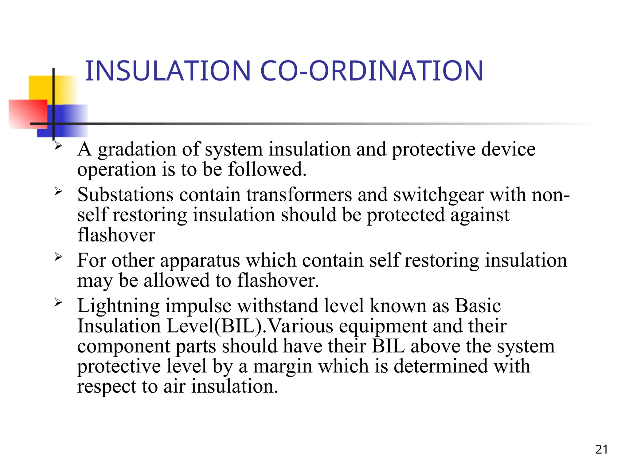
INSULATION CO-ORDINATION
Agradation of system insulation and protective device
operation is to be followed.
Substations contain transformers and switchgear with non-
self restoring insulation should be protected against
flashover
For other apparatus which contain self restoring insulation
may be allowed to flashover.
Lightning impulse withstand level known as Basic
Insulation Level(BIL).Various equipment and their
component parts should have their BIL above the system
protective level by a margin which is determined with
respect to air insulation.
22.
22
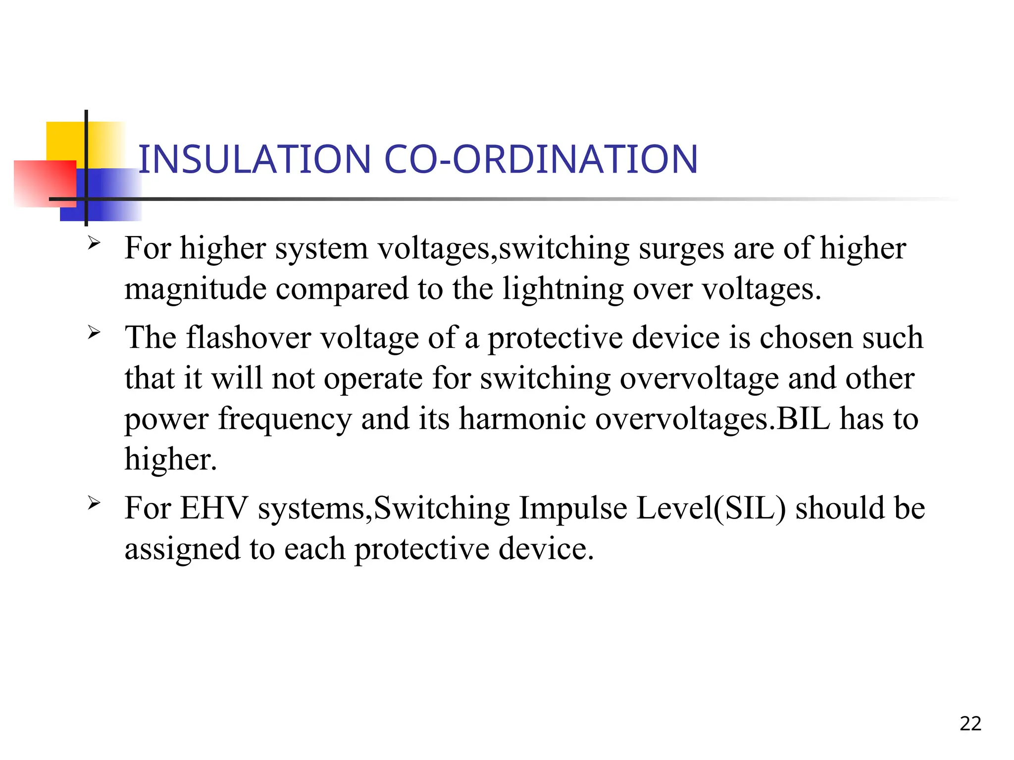
INSULATION CO-ORDINATION
Forhigher system voltages,switching surges are of higher
magnitude compared to the lightning over voltages.
The flashover voltage of a protective device is chosen such
that it will not operate for switching overvoltage and other
power frequency and its harmonic overvoltages.BIL has to
higher.
For EHV systems,Switching Impulse Level(SIL) should be
assigned to each protective device.