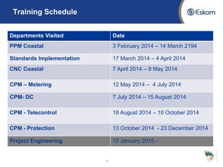
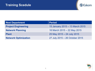
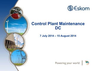
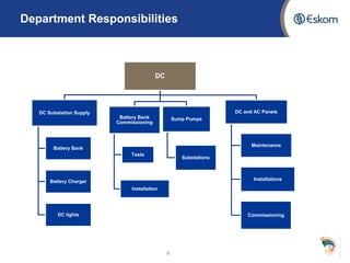
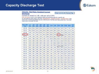
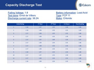
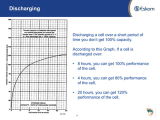
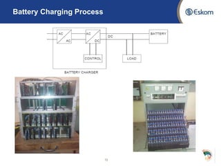
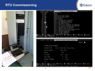
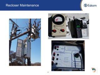
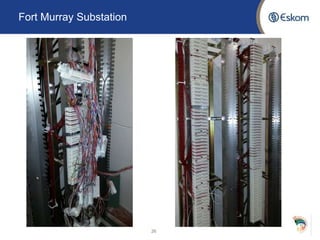
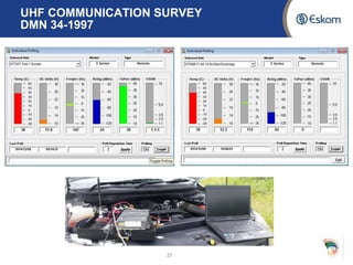
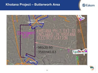
EIT Evaluation 2
Presented By : Ernst de Villiers
January 2015
Mentor : Lukas Van de Merwe
Contents
• Eskom’s 5 Life Saving Rules
• Training Schedule
• Control Plant Maintenance (CPM)
DC
Telecontrol
Protection
• Network Engineering Design (NED)
 Electrification
2
Eskom’s 5 Life Saving Rules
• Open, isolate, test, earth, bond and/or insulate before touch
• Hook up at heights
• Buckle up during vehicle trips
• No one is to work under the influence of alcohol or/and drugs
• Having a valid worker’s permit
3
4
Training Schedule
Departments Visited Date
PPM Coastal 3 February 2014 – 14 March 2194
Standards Implementation 17 March 2014 – 4 April 2014
CNC Coastal 7 April 2014 – 9 May 2014
CPM – Metering 12 May 2014 – 4 July 2014
CPM- DC 7 July 2014 – 15 August 2014
CPM - Telecontrol 18 August 2014 – 10 October 2014
CPM - Protection 13 October 2014 - 23 December 2014
Project Engineering 15 January 2015 -
Training Scedule
5
Next Department Period
Project Engineering 15 January 2015 – 13 March 2015
Network Planning 16 March 2015 – 22 May 2015
Plant 25 May 2015 – 24 July 2015
Network Optimization 27 July 2015 – 26 October 2015
Maintenance and Operations Structure
6
Control Plant Maintenance
DC
7 July 2014 – 15 August 2014
Department Responsibilities
8
DC
DC Substation Supply
Battery Bank
Battery Charger
DC lights
Battery Bank
Commissioning
Tests
Installation
Sump Pumps
Substations
DC and AC Panels
Maintenance
Installations
Commissioning
Battery Banks
• DC batteries banks in substations are supplying the protection and
communication modules such as RTU’s and protection panels.
• Two types of batteries used in ECOU:
• Nickel-Cadmium
• Lead-Acid
9
Battery and Charger Maintenance
DPC 34-1039
Battery Capacity
• The ability of the battery to provide a required steady D.C. current for
a specified period of time, such that the voltage stays above a certain
minimum value.
Specific gravity
• In lead-acid batteries there is a change in the specific gravity of the
electrolyte during charge and discharge, and this forms a valuable
indication of the state of charge of the battery. The chemical reaction
during charge absorbs from, and releases water into, the electrolyte.
10
11
Capacity Discharge Test
A capacity discharge test is done to determine the ampere - hour capacity of
the battery according to the labelled specification.
Battery Specification – FCP 11 160Ah
In the figure below, is a lead acid battery part of the 110V battery bank at
Chaba substation.
2016-03-01 12
Capacity Discharge Test
Initial Rating 1st Hour 2nd Hour 2.5 Hours Final Reading
1 2.18 1.97 1.93 1.90 1.86
2 2.18 1.98 1.93 1.91 1.89
3 2.17 1.98 1.93 1.91 1.86
4 2.17 1.98 1.93 1.90 1.86
5 2.17 1.97 1.89 1.92 1.87
6 2.17 1.98 1.94 1.91 1.86
7 2.17 1.98 1.93 1.92 1.86
8 2.17 1.98 1.94 1.91 1.84
9 2.18 1.97 1.94 1.92 1.86
10 2.17 1.97 1.93 1.90 1.88
11 2.17 1.98 1.94 1.91 1.86
12 2.18 1.98 1.94 1.92 1.86
13
Failing Voltage: 1.8
Test done: Ernst de Villiers
Discharge current rate: 38.2A
Battery information: Lead Acid
Type: FCP 11
Make: Chloride
Discharging
14
Discharging a cell over a short period of
time you don’t get 100% capacity.
According to this Graph, If a cell is
discharged over:
• 8 hours, you can get 100% performance
of the cell,
• 4 hours, you can get 80% performance
of the cell,
• 20 hours, you can get 120%
performance of the cell,
Battery Charging Process
15
16 16
Communications
.•Charge Fail – No charging operation
•DC earth fault - DC earth faults cause incorrect tripping of protection equipment.
17 17
Communications
.•Load Overvoltage - As soon as the voltage rises above the maximum tolerance
allowed by the load, an alarm is signalled and the charger is shut off electronically to
prevent damage to the load.
Some battery chargers are equipped with voltage dropping diodes as a form of
voltage regulation to decrease the voltage during an overvoltage. These diodes are
visible in the figure below.
2016-03-01 18
AC/DC Panels
Before the AC/DC panel are explained, the figure below illustrates the scope
of works for the DC department to see exactly where these panels fit into the
substation commission.
AC/DC Panels
19
Transformer Sump Pump
20
• .
Control Plant Maintenance
Telecontrol
18 August 2014 – 10 October 2014
Department Responsibilities
22
Telecontrol
Maintenance
Reclosers
RTU
IDF
Commissioning
Substation
Communications
Reclosers
Surveys
Recloser
Placement
Remote Terminal Unit
23
RTU Commissioning
24
Recloser Maintenance
25
Fort Murray Substation
26
UHF COMMUNICATION SURVEY
DMN 34-1997
27
Control Plant Maintenance
Protection
18 August 2014 – 10 October 2014
Power Transformer Testing
Tests performed on Spare TRFR for Duke S/S
29
Routine Tests Commissioning Tests
Voltage Ratio Vector Group
Positive Sequence
Impedance Test
Zero Sequence Impedance
Test
Winding Insulation Test Magnetisation Test
Winding Resistance Oil and Winding
Temperature Test
Routine Test - Turn Ratio
30
Primary
Voltage
Secondary
Voltage
Result - Turn Ratio
• Ratio is below the allowed error of 0.5%
31
• The purpose of impedance measurements is to detect shipping damage by
comparison with nameplate values and with diagnostic tests. Percent
impedance measurements will differ for each tap position.
• An Impedance test is useful for determining loose or high-resistance
connections. between test and nameplate values can indicate future failure
due to short –circuited windings or damaged core.
𝑍% =
𝑉 𝑀𝑒𝑎𝑠𝑢𝑟𝑒𝑑
1.73 𝑥 𝐼 𝑀𝑒𝑎𝑠𝑢𝑟𝑒𝑑
x
𝑅𝑎𝑡𝑒𝑑 𝑀𝑉𝐴
(𝑅𝑎𝑡𝑒𝑒 𝑉𝑜𝑙𝑡𝑎𝑔𝑒)2 x 100
32
Routine Test – Positive Sequence Impedance
Result - Positive Sequence Impedance
Tap Phase Voltage Current 𝒁 𝑪𝒂𝒍𝒄𝒖𝒍𝒂𝒕𝒆𝒅 𝒁 𝑪𝒐𝒓𝒆 Z %
1
Red 230.7 44.9 5.138
5.169 5.34White 236.7 45.8 5.168
Blue 236.6 45.5 5.2
5
Red 23.1.3 43.9 5.263
5.27 5.44White 237.4 45.2 5.252
Blue 237.5 44.9 5.29
17
Red 231.9 41.7 5.561
5.585 5.77White 237.9 42.6 5.582
Blue 237.8 42.4 5.608
33
• This test is done to provide an indication of the no-load current drawn by the
transformer; hence the magnetization current set up due to losses in the
electric circuit and losses in the magnetic circuit due to e.g. shorted core
laminations. The insulating varnish could be damaged by sustained high
current faults resulting in a heated core.
34
Commissioning Test – Magnetisation Test
35
Commissioning Test – Magnetisation Test
• The calculation of earth fault currents on the power system requires the zero-
sequence impedance of transformers to be known.
• The flow of zero-sequence current through a transformer occurs under earth
fault conditions and only if the transformer has a star winding with the neutral
point grounded and has a secondary/tertiary winding which is able to produce
balancing zero-sequence currents. If there is no secondary or tertiary winding
which produces the balancing zero-sequence currents, the zero-sequence
impedance of the transformer would be limited by the tank-delta effect.
36
Commissioning Test – Zero-sequence Test
Oil and Winding Temperature Test
• The oil and winding temperature gauges provide protection against internal transformer
faults and overloading.
• Since the temperature of the winding is proportional to the square of current passing
through it, the winding temperature circuit makes use of a current transformer wired in
series with one phase of the transformer winding on the load side (usually the red
phase).
• The output of the feeds a heating element that is located in the pocket for the winding
temperature gauge’s probe.
37
38
Oil and Winding Temperature Test
DISSCAAD3
39
Oil and Winding Temperature Test
Ncora TRFR Scheme 3.3/22 kV
• Installation of single phase Diff relays
• Ringing of scheme
• Modifications
• SEL 351 and SEL 387 Relays
40
Current Transformers
Protection
Current Transformers
42
CT’s play a major role when it comes to
protection and relay schemes.
When current in a circuit is too high to
apply directly to recording instruments, a
current transformer produces a reduced
current accurately proportional to the
current in the circuit, which can be
conveniently connected to measuring and
recording instruments.
CT Primary Injection
43
Differential Protection
45
This scheme is based on the principle that the input power to the power transformer under
normal conditions is equal to the output power.
Under normal conditions, no resultant current will flow into the differential relay current coil.
Whenever a fault occurs, within the protected zone, the current balance will no longer exist,
and relay contacts will close and release a trip signal to cause the certain circuit breakers to
operate in order to disconnect the faulty equipment/part
Diff Procedure – Peddie Substation
Normal Operation
• 𝐼1 − 𝐼2 = 0
Fault Operation
• 𝐼1 − 𝐼2 = 𝐼 𝑑
46
47
Diff Test Procedure – Peddie Substation
Normal Operation
𝐼1 − 𝐼2 = 0
Fault Operation
𝐼1 − 𝐼2 = 𝐼 𝑑
Diff Verification – Board Illustration
48
Restricted Earth Fault(REF)
Protection
Restricted Earth Fault (REF)
50
CT secondary of each phase of power transformer are connected together as
shown in the figure. Common terminals are connected to the secondary of a
Neutral Current Transformer or NCT.
Whenever there is an unbalancing in between three phases of the transformer,
a resultant unbalanced current flows through the close path connected to the
common terminals of the CT secondaries.
51
REF Test Procedure – Peddie Substation
HV REF
MV REF
Restricted Earth Fault(REF) - Board
Illustration
52
Network Engineering & Design
Manager: Clive Akol
Supivisor: Boifang Moumakwa
Asset Creation Structure
54
Khotana Project
• Khotana Electrification project consists of 36 villages with the total
number of connections of 3603.
• Ebongweni Village allocated to EIT with approximately 171
connections.
• Feeding from Idutywa/Butterworth 22kV network.
55
Khotana Project – Butterworh Area
56
• Preliminary Design:
The main purpose of the preliminary design is to determine the best
design alternative which will satisfy the conceptual design, costs and
need date defined by Planning in the Concept Release Approval form
and associated Planning Proposal report.
Containing:
• Scope of works
• System Configuration
• MV fault levels
• MV Voltage Intake Levels – Full load and light load
• Performance levels
57
Khotana Project - Needed
Thank you

EIT_Presentation

  • 1.
    EIT Evaluation 2 PresentedBy : Ernst de Villiers January 2015 Mentor : Lukas Van de Merwe
  • 2.
    Contents • Eskom’s 5Life Saving Rules • Training Schedule • Control Plant Maintenance (CPM) DC Telecontrol Protection • Network Engineering Design (NED)  Electrification 2
  • 3.
    Eskom’s 5 LifeSaving Rules • Open, isolate, test, earth, bond and/or insulate before touch • Hook up at heights • Buckle up during vehicle trips • No one is to work under the influence of alcohol or/and drugs • Having a valid worker’s permit 3
  • 4.
    4 Training Schedule Departments VisitedDate PPM Coastal 3 February 2014 – 14 March 2194 Standards Implementation 17 March 2014 – 4 April 2014 CNC Coastal 7 April 2014 – 9 May 2014 CPM – Metering 12 May 2014 – 4 July 2014 CPM- DC 7 July 2014 – 15 August 2014 CPM - Telecontrol 18 August 2014 – 10 October 2014 CPM - Protection 13 October 2014 - 23 December 2014 Project Engineering 15 January 2015 -
  • 5.
    Training Scedule 5 Next DepartmentPeriod Project Engineering 15 January 2015 – 13 March 2015 Network Planning 16 March 2015 – 22 May 2015 Plant 25 May 2015 – 24 July 2015 Network Optimization 27 July 2015 – 26 October 2015
  • 6.
  • 7.
    Control Plant Maintenance DC 7July 2014 – 15 August 2014
  • 8.
    Department Responsibilities 8 DC DC SubstationSupply Battery Bank Battery Charger DC lights Battery Bank Commissioning Tests Installation Sump Pumps Substations DC and AC Panels Maintenance Installations Commissioning
  • 9.
    Battery Banks • DCbatteries banks in substations are supplying the protection and communication modules such as RTU’s and protection panels. • Two types of batteries used in ECOU: • Nickel-Cadmium • Lead-Acid 9
  • 10.
    Battery and ChargerMaintenance DPC 34-1039 Battery Capacity • The ability of the battery to provide a required steady D.C. current for a specified period of time, such that the voltage stays above a certain minimum value. Specific gravity • In lead-acid batteries there is a change in the specific gravity of the electrolyte during charge and discharge, and this forms a valuable indication of the state of charge of the battery. The chemical reaction during charge absorbs from, and releases water into, the electrolyte. 10
  • 11.
    11 Capacity Discharge Test Acapacity discharge test is done to determine the ampere - hour capacity of the battery according to the labelled specification. Battery Specification – FCP 11 160Ah In the figure below, is a lead acid battery part of the 110V battery bank at Chaba substation.
  • 12.
  • 13.
    Capacity Discharge Test InitialRating 1st Hour 2nd Hour 2.5 Hours Final Reading 1 2.18 1.97 1.93 1.90 1.86 2 2.18 1.98 1.93 1.91 1.89 3 2.17 1.98 1.93 1.91 1.86 4 2.17 1.98 1.93 1.90 1.86 5 2.17 1.97 1.89 1.92 1.87 6 2.17 1.98 1.94 1.91 1.86 7 2.17 1.98 1.93 1.92 1.86 8 2.17 1.98 1.94 1.91 1.84 9 2.18 1.97 1.94 1.92 1.86 10 2.17 1.97 1.93 1.90 1.88 11 2.17 1.98 1.94 1.91 1.86 12 2.18 1.98 1.94 1.92 1.86 13 Failing Voltage: 1.8 Test done: Ernst de Villiers Discharge current rate: 38.2A Battery information: Lead Acid Type: FCP 11 Make: Chloride
  • 14.
    Discharging 14 Discharging a cellover a short period of time you don’t get 100% capacity. According to this Graph, If a cell is discharged over: • 8 hours, you can get 100% performance of the cell, • 4 hours, you can get 80% performance of the cell, • 20 hours, you can get 120% performance of the cell,
  • 15.
  • 16.
    16 16 Communications .•Charge Fail– No charging operation •DC earth fault - DC earth faults cause incorrect tripping of protection equipment.
  • 17.
    17 17 Communications .•Load Overvoltage- As soon as the voltage rises above the maximum tolerance allowed by the load, an alarm is signalled and the charger is shut off electronically to prevent damage to the load. Some battery chargers are equipped with voltage dropping diodes as a form of voltage regulation to decrease the voltage during an overvoltage. These diodes are visible in the figure below.
  • 18.
    2016-03-01 18 AC/DC Panels Beforethe AC/DC panel are explained, the figure below illustrates the scope of works for the DC department to see exactly where these panels fit into the substation commission.
  • 19.
  • 20.
  • 21.
    Control Plant Maintenance Telecontrol 18August 2014 – 10 October 2014
  • 22.
  • 23.
  • 24.
  • 25.
  • 26.
  • 27.
  • 28.
    Control Plant Maintenance Protection 18August 2014 – 10 October 2014
  • 29.
    Power Transformer Testing Testsperformed on Spare TRFR for Duke S/S 29 Routine Tests Commissioning Tests Voltage Ratio Vector Group Positive Sequence Impedance Test Zero Sequence Impedance Test Winding Insulation Test Magnetisation Test Winding Resistance Oil and Winding Temperature Test
  • 30.
    Routine Test -Turn Ratio 30 Primary Voltage Secondary Voltage
  • 31.
    Result - TurnRatio • Ratio is below the allowed error of 0.5% 31
  • 32.
    • The purposeof impedance measurements is to detect shipping damage by comparison with nameplate values and with diagnostic tests. Percent impedance measurements will differ for each tap position. • An Impedance test is useful for determining loose or high-resistance connections. between test and nameplate values can indicate future failure due to short –circuited windings or damaged core. 𝑍% = 𝑉 𝑀𝑒𝑎𝑠𝑢𝑟𝑒𝑑 1.73 𝑥 𝐼 𝑀𝑒𝑎𝑠𝑢𝑟𝑒𝑑 x 𝑅𝑎𝑡𝑒𝑑 𝑀𝑉𝐴 (𝑅𝑎𝑡𝑒𝑒 𝑉𝑜𝑙𝑡𝑎𝑔𝑒)2 x 100 32 Routine Test – Positive Sequence Impedance
  • 33.
    Result - PositiveSequence Impedance Tap Phase Voltage Current 𝒁 𝑪𝒂𝒍𝒄𝒖𝒍𝒂𝒕𝒆𝒅 𝒁 𝑪𝒐𝒓𝒆 Z % 1 Red 230.7 44.9 5.138 5.169 5.34White 236.7 45.8 5.168 Blue 236.6 45.5 5.2 5 Red 23.1.3 43.9 5.263 5.27 5.44White 237.4 45.2 5.252 Blue 237.5 44.9 5.29 17 Red 231.9 41.7 5.561 5.585 5.77White 237.9 42.6 5.582 Blue 237.8 42.4 5.608 33
  • 34.
    • This testis done to provide an indication of the no-load current drawn by the transformer; hence the magnetization current set up due to losses in the electric circuit and losses in the magnetic circuit due to e.g. shorted core laminations. The insulating varnish could be damaged by sustained high current faults resulting in a heated core. 34 Commissioning Test – Magnetisation Test
  • 35.
    35 Commissioning Test –Magnetisation Test
  • 36.
    • The calculationof earth fault currents on the power system requires the zero- sequence impedance of transformers to be known. • The flow of zero-sequence current through a transformer occurs under earth fault conditions and only if the transformer has a star winding with the neutral point grounded and has a secondary/tertiary winding which is able to produce balancing zero-sequence currents. If there is no secondary or tertiary winding which produces the balancing zero-sequence currents, the zero-sequence impedance of the transformer would be limited by the tank-delta effect. 36 Commissioning Test – Zero-sequence Test
  • 37.
    Oil and WindingTemperature Test • The oil and winding temperature gauges provide protection against internal transformer faults and overloading. • Since the temperature of the winding is proportional to the square of current passing through it, the winding temperature circuit makes use of a current transformer wired in series with one phase of the transformer winding on the load side (usually the red phase). • The output of the feeds a heating element that is located in the pocket for the winding temperature gauge’s probe. 37
  • 38.
    38 Oil and WindingTemperature Test DISSCAAD3
  • 39.
    39 Oil and WindingTemperature Test
  • 40.
    Ncora TRFR Scheme3.3/22 kV • Installation of single phase Diff relays • Ringing of scheme • Modifications • SEL 351 and SEL 387 Relays 40
  • 41.
  • 42.
    Current Transformers 42 CT’s playa major role when it comes to protection and relay schemes. When current in a circuit is too high to apply directly to recording instruments, a current transformer produces a reduced current accurately proportional to the current in the circuit, which can be conveniently connected to measuring and recording instruments.
  • 43.
  • 44.
  • 45.
    Differential Protection 45 This schemeis based on the principle that the input power to the power transformer under normal conditions is equal to the output power. Under normal conditions, no resultant current will flow into the differential relay current coil. Whenever a fault occurs, within the protected zone, the current balance will no longer exist, and relay contacts will close and release a trip signal to cause the certain circuit breakers to operate in order to disconnect the faulty equipment/part
  • 46.
    Diff Procedure –Peddie Substation Normal Operation • 𝐼1 − 𝐼2 = 0 Fault Operation • 𝐼1 − 𝐼2 = 𝐼 𝑑 46
  • 47.
    47 Diff Test Procedure– Peddie Substation Normal Operation 𝐼1 − 𝐼2 = 0 Fault Operation 𝐼1 − 𝐼2 = 𝐼 𝑑
  • 48.
    Diff Verification –Board Illustration 48
  • 49.
  • 50.
    Restricted Earth Fault(REF) 50 CT secondary of each phase of power transformer are connected together as shown in the figure. Common terminals are connected to the secondary of a Neutral Current Transformer or NCT. Whenever there is an unbalancing in between three phases of the transformer, a resultant unbalanced current flows through the close path connected to the common terminals of the CT secondaries.
  • 51.
    51 REF Test Procedure– Peddie Substation HV REF MV REF
  • 52.
    Restricted Earth Fault(REF)- Board Illustration 52
  • 53.
    Network Engineering &Design Manager: Clive Akol Supivisor: Boifang Moumakwa
  • 54.
  • 55.
    Khotana Project • KhotanaElectrification project consists of 36 villages with the total number of connections of 3603. • Ebongweni Village allocated to EIT with approximately 171 connections. • Feeding from Idutywa/Butterworth 22kV network. 55
  • 56.
    Khotana Project –Butterworh Area 56
  • 57.
    • Preliminary Design: Themain purpose of the preliminary design is to determine the best design alternative which will satisfy the conceptual design, costs and need date defined by Planning in the Concept Release Approval form and associated Planning Proposal report. Containing: • Scope of works • System Configuration • MV fault levels • MV Voltage Intake Levels – Full load and light load • Performance levels 57 Khotana Project - Needed
  • 58.

Editor's Notes

  • #12 NB – Reactor: Current Limiting
  • #13 CT – VT for output measurement REV Swittch