SlideShare a Scribd company logo
Prepared By: KAMAL DEEP 
Roll No. 115060 
Sem: 7th
 TIFAC CORE means TECHNOLOGY INFORMATION FORCASTING AND ASSCEMENT COUNCIL CENTRE 
OF RELEVANCAND EXCELLENCE. 
 Abstract-Centre of Relevance & Excellence (CORE) in “Power Transformer Diagnostics” came into existence since 1st 
September, 2004. 
 National Institute of Technology Hamirpur, Himachal Pradesh, India is one such centre in the area of Power Transformer 
Diagnostics established in September 2005. The activities of this centre are supported by TIFAC, an autonomous entity 
under Department of science and technology, Government of INDIA and from the Industry side by Himachal Pradesh State 
Electricity Board (HPSEB) Ltd. 
 SURVAY LITERATURE: Transformer failure statistics reported in literature indicate that most failures have occurred 
before reaching their expected designed life. Transformer failures related to transformer health conditions, such as dielectric 
problems. 
 Health Index: A Health Index is a means of combining information related to the physical condition of a transformer such 
as inspection results, test results or condition related risk factors, to provide a comparable measure of condition for individual 
transformers in terms of proximity to end of life or probability of failure. 
 41 % of failures were due to on-load tap changers (O.L.T.C) 
 19 % were due to the windings. 
 53 % mechanical and 31% dielectric 
 On transformers without on-load tap changers 
 26.6 % of failures were due to the windings 
 6.4 % were due to the magnetic circuit 
 33.3 % were due to terminals 
 17.4 % were due to the tank and dielectric fluid 
 11 % were due to other accessories, 
 4.6 % were due to the tap changer
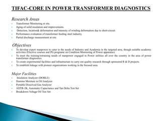
TIFAC-CORE IN POWER TRANSFORMER DIAGNOSTICS 
Research Areas 
 Transformer Monitoring at site. 
 Aging of solid insulation and improvements. 
 Detection, location& deformation and intensity of winding deformation due to short-circuit. 
 Performance evaluation of transformer feeding steel industry. 
 Partial discharge measurement at site. 
Objectives 
 To develop expert manpower to cater to the needs of Industry and Academia in the targeted area, though suitable academic 
activities (Elective courses and PG programe on Condition Monitoring of Power apparatus). 
 To meet the training/retraining needs of manpower engaged in Power utilities all over the country in the area of power 
transformer diagnostics. 
 To create experimental facilities and infrastructure to carry out quality research through sponsored R & D projects. 
 To establish linkage with pioneer organizations working in the focused area. 
Major Facilities 
 Insulation Analyzer (DOBLE) 
 Domino Moisture in Oil Analyzer 
 Portable Dissolved Gas Analyzer 
 ADTR-2K, Automatic Capacitance and Tan Delta Test Set 
 Breakdown Voltage Oil Test Set
 High voltage are used for wide variety of applications covering the power systems, industry and research 
laboratories. High voltage are applied in laboratories in nuclear research, in partical accelerator and van de graaff 
generator. 
Generation and transmission of electric energy 
 The first public power station was put into service in 1882 in London. 
 To produce direct current at low voltage. 
 Its service was limited to highly localized areas. 
 Used mainly for electric lighting. 
 The first major AC power station was commissioned in 1890 at Deptford. 
 To supply power over a distance of 28 miles. 
 To produce alternative current at high voltage of 10 kV. 
 Two principle factors influences the development of power transmission networks. 
 To make full use of economic generation, transmission networks must be interconnected for pooling of generation 
in an integrated system. 
 Bulk transfer over long distances. 
Generation and transmission of electric energy 
 HVDC permits a higher power density as compared to AC transmission. 
 HVDC provides an economic solution for interconnecting asynchronous AC systems (back-to-back installation). 
 Major DC systems in chronological order of their installations
Voltage Stresses 
 The IEC and its national counterparts (IET, IEEE, VDE, etc.) define high voltage circuits as those with more than 
1000 V for AC and at least 1500 V for DC. 
 In electric power transmission engineering, high voltages usually considered any voltage over approximately 35 
kV. 
 AC systems: 
 High voltage levels: 35-220 kV 
 Extra high voltage (EHV) levels: ≥330 kV and <1000 kV 
 Ultra high voltage (UHV) levels: 1000 kV and above 
 DC systems: 
 HVDC levels: 600 kV and below 
 UHVDC levels: above 600 kV 
 Operating voltage: 
 Normal operating voltage does not severely stress the power system’s insulation. 
 only in special circumstances, for example under pollution conditions, may operating voltages cause problems 
to external insulation. 
 operating voltage determines the dimensions of the insulation which forms part of electrical equipment. 
 Overvoltage's 
 Voltage stresses on power systems arise from various overvoltage's. 
 External overvoltage's: associating with lightning strokes on lines 
 Internal overvoltage's: generated by changes in the operating conditions of systems, such as switching 
operation (switching overvoltage), faults on systems or fluctuations in loads (voltage rise and fluctuation 
overvoltage).
Testing voltages 
 It is necessary to test HV equipment during its development stage and prior to commissioning. 
 The magnitude and type of test voltage varies with the rated voltage of a particular apparatus. 
 Basic classification of testing voltages 
◦ Testing with power frequency voltages 
◦ Testing with lightning impulse voltages 
◦ Testing with switching impulse voltages 
◦ Testing with DC voltages 
◦ Testing with very low-frequency voltages 
High voltage engineering consists of generation, measurement, and control of high voltages, 
dielectric discharges and electrical insulation breakdown, over voltages and their protection, and 
electrical insulation condition monitoring and diagnosis, et al. 
Dielectrics and electrical insulation 
Over voltages and Insulation coordination in electric 
power systems 
High voltage testing techniques
Relationships? 
Reliable insulation is related to application of high voltage systems. Electrical 
insulation is the physical basis of high voltage engineering. 
Over voltages may have much greater 
magnitudes than normal operating voltages. 
They do severely stress the power system’s 
insulation. 
High voltage tests ensure high voltage system 
to be operated safely. 
HV Generation? 
HV measurement? 
HV testing? 
I 
Insulation 
HV testing techniques Overvoltage
Main contents of the course 
Electrical insulation 
 Dielectrics or insulating material 
 Properties and phenomenon of dielectrics in high fields. 
 Insulation structures and electric field distribution 
 How to design proper insulation structures to satisfy requirements of field distribution in or around HV equipment. 
 Voltage stresses on electric insulation 
 AC, DC, impulse, and combined voltages should be considered for insulation structure designing. 
Over voltages 
 Occurrence, development, propagation of over voltages and their influence factors. 
 Approaches to limit overvoltage on HV systems. 
 Coordination of voltage stresses, insulation, and overvoltage protection devices. 
High voltage testing techniques 
 How to generate high voltage 
 Economic and flexible HV testing equipment 
 How to execute high voltage experiment 
 HV testing programs and standards 
 How to measure high voltage 
 Measurement of High field, tiny quantity of parameters of HV equipment of systems, transient parameter measurement.
MECHANISM OF BREAKDOWN OF GASES 
 Gases have dielectric properties comparable or superior to each other. There are two basic reasons for 
carrying out such investigations. 
◦ Firstly, the aims are to develop an insulating medium, which is technically as well as economically 
attractive. 
◦ The other reason is to obtain a better understanding of the breakdown mechanisms operating in 
compressed gases, and their gas mixtures. 
 Where a voltage difference exists between two conductors, it is necessary to keep them apart to prevent the 
undesirable flow of electrical current from the one conductor to the other. When the conductors are 
separated (isolated from each other) a layer of gas (air) fills the space between them, forming the electrical 
insulation. the field strength in this gap will depend on the voltage difference and the gap size. if the field 
strength in the gap exceeds a certain threshold, the gas in the gap will seize to act as an insulating material, 
but will become ionized and break down. Prior to flashover, corona discharges occur in regions of high field 
strength. 
 The most commonly used insulating gas is air at atmospheric pressure, as employed on overhead power 
lines and open air substations. 
Breakdown Voltage ofAir 
 The breakdown in air (spark breakdown) is the transition of a non-sustaining discharge into a self-sustaining 
discharge. The buildup of high currents in a breakdown is due to the ionization in which electrons and ions 
are created from neutral atoms or molecules, and their migration to the anode and cathode respectively leads 
to high currents.
Flashover of uniform gaps: The effect of pressure and gap length: 
 In small uniform gaps it has been found empirically that, at standard pressure (1 bar = 101,3 
kPa = 760 mm Hg) and temperature (20 °C), that breakdown occurs at a field strength of 
approximately 30 kV/ cm. 
 At lower pressures the gas molecules are less densely packed and the mean free path between 
collisions is longer. The electrons therefore attain higher speeds before colliding with the gas 
molecules, resulting in a lower flashover stress for the same gap. At very low pressures, such 
as used in vacuum contactors, the gas atoms are so far apart that the collision probability is 
low, with the result that ionization and flashover takes place at a much higher value. 
 Two identical metallic spheres are separated by certain distance form a sphere gap. Also, the 
gap length between the spheres should not exceed a sphere radius. If these conditions are 
satisfied and the specifications regarding the shape, mounting, clearances of the spheres
Flashover of non-uniform gaps: the polarity effect 
 If the voltage across a non-uniform field gap is increased, avalanche 
activity occurs in the regions where the field is high . 
 If the voltage is increased beyond the corona inception level, some 
avalanches develop into streamer discharges, bridging the gap to cause a 
complete flashover. The flashover voltage of a non-uniform gap is 
therefore much lower than that of a uniform gap of the same size. The "rule 
of thumb" of 30 kV/ cm therefore does not apply to non-uniform gaps. 
 In this arrangement the ground effect also affects the breakdown voltage of 
the rod-plate air gaps but in a quite different way than the Polarity Effect.
Corona discharges 
 In the case of a non uniform gap the maximum field strength will occur near electrodes of small radius of curvature. 
The ionization threshold is therefore exceeded only in these areas. Partial discharges or corona therefore occurs in 
these areas. Corona is a self-sustaining discharge, occurring in the parts of the gap where the critical field strength is 
exceeded. If the voltage is further increased, final flashover develops from the corona. 
 Apart from being a pre-cursor of flashover, corona is also undesirable on the power system due to the electromagnetic 
interference caused, the additional corona losses and the material (insulation) degradation due to the ultra violet radiation, 
emanating from the corona.
Problems caused by corona: 
 Corona can be noticed as a bluish luminous discharge on conductors and ozone is formed. 
 Interference (Radio Interference Voltage, RIV): The rapidly varying corona current pulses, especially the positive 
streamer discharges, radiate electromagnetic interference in the range 0.2 to 10 MHz 
Losses: 
 The continuous corona current, shown in Figure 3.16, has a 50 Hz component that causes a power loss on the line. 
Normally, a well designed transmission line will have a low amount of radio-interference (RI) and therefore also 
small losses. During rain, however, corona forms on droplets on the conductor and both RI and power losses occur. 
Under such conditions, losses of tens of MW can occur on a 500 kV line. 
Measures to curb Corona: 
 As corona is caused by the field intensification at sharp points, having a small radius of curvature. Sharp edges and points 
due to poor workmanship on high voltage hardware must therefore be avoided. Lines are normally designed to limit the 
surface gradient to low values. For EHV lines it is necessary to use bundled conductors, i.e. each phase consists of a number 
of parallel conductors as explained in section 2.2.3. On the 800 kV lines 6 conductors are used. The six conductors are 
equivalent to one conductor with a large radius and the surface gradient and losses are therefore low. Likewise, a corona ring 
can be fitted to shield stress concentrations 
Useful applications of Corona: 
 Besides the nuisance value on the power system, corona has many useful applications, including: photocopying machines, 
electrostatic dust precipitators and ozone generators.
INSULATORS 
 An insulator, also called a “dielectric”, is a material that resists the flow of 
electric current in it. An insulating material has atoms that has tightly 
bonded valence electrons. These materials are used in parts of electrical 
equipment, also called insulators, with the aim to support or separate 
electrical conductors without passing current through themselves. Some 
materials such as glass, paper or Teflon, mica are very good electrical 
insulators. 
Solid and Liquid Insulating Materials 
 The electrical performance of liquids and solids will be better than 
that of gases. In practice, the electric strength of liquid and solid 
materials are however less than predicted due to impurities and 
imperfections. 
 Liquid and solid materials also classed as dielectrics, i.e. they have 
the property of polarization, resulting in a dielectric constant that is 
higher than unity.
Dielectric 
 The dielectric consists of dipoles. The dipoles could be due to the positive and negative 
charge carriers of the molecules not coinciding or could be due to the charge distribution in 
the crystal structure of the material. When not energized, the dipoles are randomly arranged. 
At the application of a voltage between the electrodes an electric field is established that acts 
on the dipoles to align them.
Breakdown 
 Insulators suffer from the phenomenon of electrical breakdown. When the electric field applied across an 
insulating substance exceeds the threshold breakdown field for that substance, which is proportional to the 
band gap energy of the insulating material, the insulator suddenly turns into a resistor, sometimes with 
disastrous results. 
 During electrical breakdown, any free charge carrier being accelerated by the strong e-field will have 
enough velocity to knock electrons from any atom it strikes. These free electrons and ions are in turn 
accelerated and strike other atoms, creating more charge carriers, in a chain reaction. Rapidly the insulator 
becomes filled with mobile carriers, and its resistance drops to a low level. In air, the outbreak of 
conductivity is called "corona discharge" or a "spark." Similar breakdown can occur within any insulator, 
even within the bulk solid of a material. 
The electrical breakdown of an insulator due to excessive voltage can occur in one of two ways: 
• Puncture voltage:- is the voltage across the insulator which causes a breakdown and conduction through the 
interior of the insulator. The heat resulting from the puncture arc usually damages the insulator irreparably. 
• Flashover voltage:- is the voltage which causes the air around or along the surface of the insulator to break 
down and conduct, causing a 'flashover' arc along the outside of the insulator. They are usually designed to 
withstand this without damage. 
Most high voltage insulators are designed with a lower flashover voltage than puncture voltage, so they will 
flashover before they puncture, to avoid damage.
BREAKDOWN IN SOLID 
Solid insulating materials are used almost in all electrical equipments, be it an electric heater or a 
500 MW generator or a circuit breaker, solid insulation forms an integral part of all electrical 
equipments especially when the operating voltages are high. The solid insulation not only 
provides insulation to the live parts of the equipment from the grounded structures, it sometimes 
provides mechanical support to the equipment. In general, of course, a suitable combination of 
solid, liquid and gaseous insulations are 
used. 
The processes responsible for the breakdown of gaseous dielectrics are governed by the rapid 
growth of current due to emission of electrons from the cathode, ionization of the gas particles and 
fast development of avalanche process. When breakdown occurs the gases regain their dielectric 
strength very fast, the liquids regain partially and solid dielectrics lose their strength completely. 
Mechanisms: 
(i) Intrinsic Breakdown 
(ii) Electromechanical Breakdown 
(iii) Breakdown Due to Treeing and Tracking 
(iv) Thermal Breakdown 
(v) Electrochemical Breakdown
Intrinsic breakdown: 
 If the material under test is pure and homogeneous, the temperature and environmental conditions are carefully controlled, 
and the sample is so stressed that there are no external discharges. With under voltages applied for a short time the electric 
strength increases up to an upper limit which is called the intrinsic electric strength. 
 The intrinsic breakdown is accomplished in times of the order of 10-8 sec. and has therefore been postulated to be electronic 
in nature. The stresses required for an intrinsic breakdown are well in excess of 106 volt/cm. 
Streamer breakdown: 
 An electron entering the conduction band of the dielectric at the cathode will drift towards the anode under the influence of 
the field gaining energy between collisions and loosing it on collisions. On occasions the free path may be long enough for 
the energy gain to exceed the lattice ionization energy and additional electron is produced on collision. The process is 
repeated and may lead to formation of an electron avalanche similar to gases. 
Electromechanical breakdown: 
 Substances which can deform appreciably without fracture may collapse when the electrostatic compression forces on the 
test specimen exceeds its mechanical compressive strength. The compression force arises from the electrostatic attraction 
between surface charges which appear when the voltage is applied. The pressure exerted when the reaches about 106 volt/cm 
may be several KN/m2. This breakdown due to mechanical stresses is called electromechanical breakdown. 
Thermal breakdown: 
 When insulation is stressed because of conduction currents and dielectric losses due to polarization, heat is continuously 
generated within the dielectric. In general conductivity increases with temperature, conditions of instability are reached when 
the rate of heating exceeds the rate of cooling and the specimen may undergo thermal breakdown. 
Breakdown due to internal discharges: 
 Solid insulating materials, and to a lesser extent liquid dielectrics contains voids or cavities within the medium or at the 
boundaries between the dielectric and the electrodes. These voids are generally filled with a medium of lower dielectric 
strength, and the dielectric constant of the medium in the voids is lower than that of the insulation. Hence the electric field 
strength in the voids is higher than that across the dielectric. Therefore even under normal working voltages the field in the 
voids may exceed their breakdown value, and breakdown may occur.
Breakdown of solid insulating materials: 
Solid insulator Thickness(mm) Breakdown 
Voltage (KV) 
Dielectric 
strength(KV/mm 
) 
Plastic sheet 2 25 13 
Rubber sheet 3 35 11.57 
Winding paper 0.1 26 26 
Glass sheet 3 20 6.66
BREAKDOWN IN LIQUID DIELECTRICS 
 Liquid dielectrics are used for filling transformers, circuit breakers and as impregnants in high voltage cables and capacitors. 
For transformer, the liquid dielectric is used both for providing insulation between the live parts of the transformer and the 
grounded parts besides carrying out the heat from the transformer to the atmosphere thus providing cooling effect. For circuit 
breaker, again besides providing insulation between the live parts and the grounded parts, the liquid dielectric is used to 
quench the arc developed between the breaker contacts. 
 The liquid dielectrics mostly used are petroleum oils. Other oils used are synthetic hydrocarbons and halogenated 
hydrocarbons and for very high temperature applications sillicone oils and fluorinated hyrocarbons are also used. 
 The three most important properties of liquid dielectric are 
 The dielectric strength 
 The dielectric constant and 
 The electrical conductivity. 
 Other important properties are viscosity, thermal stability, specific gravity, flash point etc. 
 Transformer oil is the most commonly used liquid in power apparatus. It is almost colourless liquid Consisting of mixture of 
H-C which include parafinns ,isoparafinns,nepthalin,aromatic which is service the liq. In T/F is subjected to prolong heating 
process with there time the oil darken due to the formation of the acid and resin of sludge in the liquid. Some of the acid are 
corrosive the solid insulator material and metal part in the transformer liquid dielectric normally are the mixture of 
hydrocarbons and normally weakly polarised when used for electrical insulator purpose. They should be free from mixture. 
 Presence of water in oil effect the electrical strength. 
 Presence of water 0.01% reduces the electrical strength about 20 %. 
 switch on the apparatus. 
 The system is micro-processor based and its take the reading of breakdown and calculate its average. 
 The printed result came out from the system. 
 Now start the manual mode and repeat it. 
 System take reading.
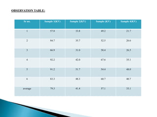
OBSERVATION TABLE: 
Sr no. Sample 1(KV) Sample 2(KV) Sample (KV) Sample 4(KV) 
1 57.8 33.8 49.2 21.7 
2 84.7 35.7 52.5 26.6 
3 66.9 31.0 58.4 26.5 
4 92.2 42.0 67.6 35.1 
5 91.2 51.7 54.4 48.0 
6 83.3 48.3 60.7 40.7 
average 79.3 41.4 57.1 33.1
 Flash point: 
 The flash point of volatile material is the lowest temperature at which it can vapourised to form an mixture in air. 
 Measuring a flash point require a inition source. At the flash point the vapour may cease to burn when the source of igination 
is removed. 
 Flash point is indepdent to the temperature. 
 The flash point is offten use as a discrutive characterstics of liquid fuel. And it also use to help characterise the fire hazzard 
of liquid.
Interfacial tension 
 Interfacial tension is the force that hold the surface of a particular phase together and normally measured in 
dynes/cm or N/m. the surface tension between gas crude oil ranges from 0 to 34 dynes/cm. it is function of 
temperature and pressure. 
 The molecules at the surface of both of these liquids experience unbalanced forces of 
attraction. These unbalanced forces at the surface of separation between the two 
immiscible liquids (i.e., at the interface) give rise to interfacial tension. It can be defined 
in the same way as the surface tension.
CONCLUSION 
 In this report, we conclude that the transformer is 
very critical and expensive Equipment. So various 
tests are used to protect the transformer from 
damage. Here we included the introduction of 
transformer, its faults location, causes and diagnosis. 
In this report we did Domino on-line test, Breakdown 
Voltage test, Solid Insulation test, Oil Insulation test, 
Insulation Analyzer test, Flash point test, Interfacial 
test, Dissolved Gas Analysis, Sweep Frequency 
Response test, Thermal images camera and include 
their result. We should successfully did all the 
practical’s and find out how to use them. In this 
report all the test contain their introduction, 
procedure, sub instruments and result. We should 
easily understand how to use the instrument for 
transformer protection and use it for long period. 

transformer dignostics on high voltage

More Related Content

What's hot

Power quality-disturbances and monitoring Seminar
Power quality-disturbances and monitoring  SeminarPower quality-disturbances and monitoring  Seminar
Power quality-disturbances and monitoring Seminar
Surabhi Vasudev
 
Introduction to Power Quality
Introduction to Power Quality Introduction to Power Quality
Introduction to Power Quality
Piyush Tandel
 
Ieee power quality distribution systems
Ieee power quality distribution systemsIeee power quality distribution systems
Ieee power quality distribution systems
Vincent Wedelich, PE MBA
 
seminar report on power quality monitoring
seminar report on power quality monitoring  seminar report on power quality monitoring
seminar report on power quality monitoring khemraj298
 
General Power Quality
General Power QualityGeneral Power Quality
General Power Quality
Power Protection Products, Inc.
 
POWER TRANSMISSION LINES 12.pptx
POWER TRANSMISSION LINES 12.pptxPOWER TRANSMISSION LINES 12.pptx
POWER TRANSMISSION LINES 12.pptx
SAYANDEY59
 
Power quality.ppt
Power quality.pptPower quality.ppt
Power quality.ppt
Krish Krishna
 
Parasitic Boost Circuit for Transform Less Active Voltage Quality Regulator
Parasitic Boost Circuit for Transform Less Active Voltage Quality RegulatorParasitic Boost Circuit for Transform Less Active Voltage Quality Regulator
Parasitic Boost Circuit for Transform Less Active Voltage Quality Regulator
IJMTST Journal
 
Power quality 1341013148
Power quality 1341013148Power quality 1341013148
Power quality 1341013148
Pradosh Dhal
 
Power quality
Power qualityPower quality
Power quality
Karansinh Parmar
 
UG POWER QUALITY (EE2028) ppt
UG POWER QUALITY (EE2028) pptUG POWER QUALITY (EE2028) ppt
UG POWER QUALITY (EE2028) ppt
Harris Raj
 
power qualit
 power qualit power qualit
power qualit
dharmesh dabhi
 
UST Power Quality Basics
UST Power Quality BasicsUST Power Quality Basics
UST Power Quality Basics
Ronald Ladouceur
 
IRJET- Improved IUPQC Controller to Provide Grid Voltage as a STATCOM
IRJET- Improved IUPQC Controller to Provide Grid Voltage as a STATCOMIRJET- Improved IUPQC Controller to Provide Grid Voltage as a STATCOM
IRJET- Improved IUPQC Controller to Provide Grid Voltage as a STATCOM
IRJET Journal
 
Improved Controller for the Dual Topology of the Unified Power Quality Condit...
Improved Controller for the Dual Topology of the Unified Power Quality Condit...Improved Controller for the Dual Topology of the Unified Power Quality Condit...
Improved Controller for the Dual Topology of the Unified Power Quality Condit...
IRJET Journal
 
Power Quality
Power QualityPower Quality
Power Quality
kunwartouseef
 
POWER QUALITY ISSUES (POWER SYSTEM AND POWER ELECTRONICS)
POWER QUALITY ISSUES (POWER SYSTEM AND POWER ELECTRONICS)POWER QUALITY ISSUES (POWER SYSTEM AND POWER ELECTRONICS)
POWER QUALITY ISSUES (POWER SYSTEM AND POWER ELECTRONICS)
Rohit vijay
 
A044040108
A044040108A044040108
A044040108
IJERA Editor
 
Power Quality
Power QualityPower Quality
Power Quality
Elshemy Mohamed
 

What's hot (20)

Power quality-disturbances and monitoring Seminar
Power quality-disturbances and monitoring  SeminarPower quality-disturbances and monitoring  Seminar
Power quality-disturbances and monitoring Seminar
 
Introduction to Power Quality
Introduction to Power Quality Introduction to Power Quality
Introduction to Power Quality
 
Ieee power quality distribution systems
Ieee power quality distribution systemsIeee power quality distribution systems
Ieee power quality distribution systems
 
seminar report on power quality monitoring
seminar report on power quality monitoring  seminar report on power quality monitoring
seminar report on power quality monitoring
 
General Power Quality
General Power QualityGeneral Power Quality
General Power Quality
 
POWER TRANSMISSION LINES 12.pptx
POWER TRANSMISSION LINES 12.pptxPOWER TRANSMISSION LINES 12.pptx
POWER TRANSMISSION LINES 12.pptx
 
Power quality.ppt
Power quality.pptPower quality.ppt
Power quality.ppt
 
Parasitic Boost Circuit for Transform Less Active Voltage Quality Regulator
Parasitic Boost Circuit for Transform Less Active Voltage Quality RegulatorParasitic Boost Circuit for Transform Less Active Voltage Quality Regulator
Parasitic Boost Circuit for Transform Less Active Voltage Quality Regulator
 
Power quality 1341013148
Power quality 1341013148Power quality 1341013148
Power quality 1341013148
 
Power quality
Power qualityPower quality
Power quality
 
UG POWER QUALITY (EE2028) ppt
UG POWER QUALITY (EE2028) pptUG POWER QUALITY (EE2028) ppt
UG POWER QUALITY (EE2028) ppt
 
power qualit
 power qualit power qualit
power qualit
 
UST Power Quality Basics
UST Power Quality BasicsUST Power Quality Basics
UST Power Quality Basics
 
IRJET- Improved IUPQC Controller to Provide Grid Voltage as a STATCOM
IRJET- Improved IUPQC Controller to Provide Grid Voltage as a STATCOMIRJET- Improved IUPQC Controller to Provide Grid Voltage as a STATCOM
IRJET- Improved IUPQC Controller to Provide Grid Voltage as a STATCOM
 
Ppt
PptPpt
Ppt
 
Improved Controller for the Dual Topology of the Unified Power Quality Condit...
Improved Controller for the Dual Topology of the Unified Power Quality Condit...Improved Controller for the Dual Topology of the Unified Power Quality Condit...
Improved Controller for the Dual Topology of the Unified Power Quality Condit...
 
Power Quality
Power QualityPower Quality
Power Quality
 
POWER QUALITY ISSUES (POWER SYSTEM AND POWER ELECTRONICS)
POWER QUALITY ISSUES (POWER SYSTEM AND POWER ELECTRONICS)POWER QUALITY ISSUES (POWER SYSTEM AND POWER ELECTRONICS)
POWER QUALITY ISSUES (POWER SYSTEM AND POWER ELECTRONICS)
 
A044040108
A044040108A044040108
A044040108
 
Power Quality
Power QualityPower Quality
Power Quality
 

Similar to transformer dignostics on high voltage

High voltage technology &amp; insulation testing
High voltage technology &amp; insulation testingHigh voltage technology &amp; insulation testing
High voltage technology &amp; insulation testing
Zeeshan Akhtar
 
Miniature prototype design and implementation of modified multiplier circuit ...
Miniature prototype design and implementation of modified multiplier circuit ...Miniature prototype design and implementation of modified multiplier circuit ...
Miniature prototype design and implementation of modified multiplier circuit ...
IAEME Publication
 
CPRI-Power quality report
CPRI-Power quality reportCPRI-Power quality report
CPRI-Power quality reportNageswar Rao
 
1 power quality-issues-problems-standards-their-effects-in-industry-with-corr...
1 power quality-issues-problems-standards-their-effects-in-industry-with-corr...1 power quality-issues-problems-standards-their-effects-in-industry-with-corr...
1 power quality-issues-problems-standards-their-effects-in-industry-with-corr...
abuaadil2510
 
1502957304lectrure_1 [Autosaved].pptx
1502957304lectrure_1 [Autosaved].pptx1502957304lectrure_1 [Autosaved].pptx
1502957304lectrure_1 [Autosaved].pptx
Tajmun1
 
1502957304lectrure_1.pptx
1502957304lectrure_1.pptx1502957304lectrure_1.pptx
1502957304lectrure_1.pptx
Tajmun1
 
Protection of 20industrial electronic.pdf
Protection of 20industrial electronic.pdfProtection of 20industrial electronic.pdf
Protection of 20industrial electronic.pdf
whmonkey
 
Transmission Line
Transmission LineTransmission Line
Transmission Line
PRITAM DEBNATH
 
EPT microproject Part B.pptx
EPT microproject Part B.pptxEPT microproject Part B.pptx
EPT microproject Part B.pptx
AnupamTarare1
 
Practical Medium and High Voltage Testing of Electrical Equipment for Enginee...
Practical Medium and High Voltage Testing of Electrical Equipment for Enginee...Practical Medium and High Voltage Testing of Electrical Equipment for Enginee...
Practical Medium and High Voltage Testing of Electrical Equipment for Enginee...
Living Online
 
63-pq.ppt
63-pq.ppt63-pq.ppt
63-pq.ppt
ssuser10f1ca
 
63-pq.ppt
63-pq.ppt63-pq.ppt
Ppt of ehv ac transmission
Ppt of ehv ac transmissionPpt of ehv ac transmission
Ppt of ehv ac transmissionSumit Kumar
 
ppt-of-ehv-ac-transmission-pdf.pdf and dc
ppt-of-ehv-ac-transmission-pdf.pdf and dcppt-of-ehv-ac-transmission-pdf.pdf and dc
ppt-of-ehv-ac-transmission-pdf.pdf and dc
ChandramohanJha7
 
ppt-of-ehv-ac-transmission-pdf.pptx
ppt-of-ehv-ac-transmission-pdf.pptxppt-of-ehv-ac-transmission-pdf.pptx
ppt-of-ehv-ac-transmission-pdf.pptx
Nagen87
 
2.Ourside.vip.Power quality improvement using dynamic voltage restorer.pdf
2.Ourside.vip.Power quality improvement using dynamic voltage restorer.pdf2.Ourside.vip.Power quality improvement using dynamic voltage restorer.pdf
2.Ourside.vip.Power quality improvement using dynamic voltage restorer.pdf
ssuser3793c8
 
windfarmgridissues.pdf
windfarmgridissues.pdfwindfarmgridissues.pdf
windfarmgridissues.pdf
sundeepsiddula
 
Wind farm grid issues
Wind farm grid issuesWind farm grid issues
Wind farm grid issues
Rohil Kumar
 

Similar to transformer dignostics on high voltage (20)

High voltage technology &amp; insulation testing
High voltage technology &amp; insulation testingHigh voltage technology &amp; insulation testing
High voltage technology &amp; insulation testing
 
Miniature prototype design and implementation of modified multiplier circuit ...
Miniature prototype design and implementation of modified multiplier circuit ...Miniature prototype design and implementation of modified multiplier circuit ...
Miniature prototype design and implementation of modified multiplier circuit ...
 
CPRI-Power quality report
CPRI-Power quality reportCPRI-Power quality report
CPRI-Power quality report
 
1 power quality-issues-problems-standards-their-effects-in-industry-with-corr...
1 power quality-issues-problems-standards-their-effects-in-industry-with-corr...1 power quality-issues-problems-standards-their-effects-in-industry-with-corr...
1 power quality-issues-problems-standards-their-effects-in-industry-with-corr...
 
1502957304lectrure_1 [Autosaved].pptx
1502957304lectrure_1 [Autosaved].pptx1502957304lectrure_1 [Autosaved].pptx
1502957304lectrure_1 [Autosaved].pptx
 
1502957304lectrure_1.pptx
1502957304lectrure_1.pptx1502957304lectrure_1.pptx
1502957304lectrure_1.pptx
 
Protection of 20industrial electronic.pdf
Protection of 20industrial electronic.pdfProtection of 20industrial electronic.pdf
Protection of 20industrial electronic.pdf
 
Transmission Line
Transmission LineTransmission Line
Transmission Line
 
Ms 2443 final
Ms 2443 finalMs 2443 final
Ms 2443 final
 
EPT microproject Part B.pptx
EPT microproject Part B.pptxEPT microproject Part B.pptx
EPT microproject Part B.pptx
 
Practical Medium and High Voltage Testing of Electrical Equipment for Enginee...
Practical Medium and High Voltage Testing of Electrical Equipment for Enginee...Practical Medium and High Voltage Testing of Electrical Equipment for Enginee...
Practical Medium and High Voltage Testing of Electrical Equipment for Enginee...
 
63-pq.ppt
63-pq.ppt63-pq.ppt
63-pq.ppt
 
63-pq.ppt
63-pq.ppt63-pq.ppt
63-pq.ppt
 
Ram
RamRam
Ram
 
Ppt of ehv ac transmission
Ppt of ehv ac transmissionPpt of ehv ac transmission
Ppt of ehv ac transmission
 
ppt-of-ehv-ac-transmission-pdf.pdf and dc
ppt-of-ehv-ac-transmission-pdf.pdf and dcppt-of-ehv-ac-transmission-pdf.pdf and dc
ppt-of-ehv-ac-transmission-pdf.pdf and dc
 
ppt-of-ehv-ac-transmission-pdf.pptx
ppt-of-ehv-ac-transmission-pdf.pptxppt-of-ehv-ac-transmission-pdf.pptx
ppt-of-ehv-ac-transmission-pdf.pptx
 
2.Ourside.vip.Power quality improvement using dynamic voltage restorer.pdf
2.Ourside.vip.Power quality improvement using dynamic voltage restorer.pdf2.Ourside.vip.Power quality improvement using dynamic voltage restorer.pdf
2.Ourside.vip.Power quality improvement using dynamic voltage restorer.pdf
 
windfarmgridissues.pdf
windfarmgridissues.pdfwindfarmgridissues.pdf
windfarmgridissues.pdf
 
Wind farm grid issues
Wind farm grid issuesWind farm grid issues
Wind farm grid issues
 

Recently uploaded

Gen AI Study Jams _ For the GDSC Leads in India.pdf
Gen AI Study Jams _ For the GDSC Leads in India.pdfGen AI Study Jams _ For the GDSC Leads in India.pdf
Gen AI Study Jams _ For the GDSC Leads in India.pdf
gdsczhcet
 
English lab ppt no titlespecENG PPTt.pdf
English lab ppt no titlespecENG PPTt.pdfEnglish lab ppt no titlespecENG PPTt.pdf
English lab ppt no titlespecENG PPTt.pdf
BrazilAccount1
 
Investor-Presentation-Q1FY2024 investor presentation document.pptx
Investor-Presentation-Q1FY2024 investor presentation document.pptxInvestor-Presentation-Q1FY2024 investor presentation document.pptx
Investor-Presentation-Q1FY2024 investor presentation document.pptx
AmarGB2
 
ASME IX(9) 2007 Full Version .pdf
ASME IX(9)  2007 Full Version       .pdfASME IX(9)  2007 Full Version       .pdf
ASME IX(9) 2007 Full Version .pdf
AhmedHussein950959
 
Pile Foundation by Venkatesh Taduvai (Sub Geotechnical Engineering II)-conver...
Pile Foundation by Venkatesh Taduvai (Sub Geotechnical Engineering II)-conver...Pile Foundation by Venkatesh Taduvai (Sub Geotechnical Engineering II)-conver...
Pile Foundation by Venkatesh Taduvai (Sub Geotechnical Engineering II)-conver...
AJAYKUMARPUND1
 
ethical hacking-mobile hacking methods.ppt
ethical hacking-mobile hacking methods.pptethical hacking-mobile hacking methods.ppt
ethical hacking-mobile hacking methods.ppt
Jayaprasanna4
 
CFD Simulation of By-pass Flow in a HRSG module by R&R Consult.pptx
CFD Simulation of By-pass Flow in a HRSG module by R&R Consult.pptxCFD Simulation of By-pass Flow in a HRSG module by R&R Consult.pptx
CFD Simulation of By-pass Flow in a HRSG module by R&R Consult.pptx
R&R Consult
 
NO1 Uk best vashikaran specialist in delhi vashikaran baba near me online vas...
NO1 Uk best vashikaran specialist in delhi vashikaran baba near me online vas...NO1 Uk best vashikaran specialist in delhi vashikaran baba near me online vas...
NO1 Uk best vashikaran specialist in delhi vashikaran baba near me online vas...
Amil Baba Dawood bangali
 
ML for identifying fraud using open blockchain data.pptx
ML for identifying fraud using open blockchain data.pptxML for identifying fraud using open blockchain data.pptx
ML for identifying fraud using open blockchain data.pptx
Vijay Dialani, PhD
 
Top 10 Oil and Gas Projects in Saudi Arabia 2024.pdf
Top 10 Oil and Gas Projects in Saudi Arabia 2024.pdfTop 10 Oil and Gas Projects in Saudi Arabia 2024.pdf
Top 10 Oil and Gas Projects in Saudi Arabia 2024.pdf
Teleport Manpower Consultant
 
J.Yang, ICLR 2024, MLILAB, KAIST AI.pdf
J.Yang,  ICLR 2024, MLILAB, KAIST AI.pdfJ.Yang,  ICLR 2024, MLILAB, KAIST AI.pdf
J.Yang, ICLR 2024, MLILAB, KAIST AI.pdf
MLILAB
 
Industrial Training at Shahjalal Fertilizer Company Limited (SFCL)
Industrial Training at Shahjalal Fertilizer Company Limited (SFCL)Industrial Training at Shahjalal Fertilizer Company Limited (SFCL)
Industrial Training at Shahjalal Fertilizer Company Limited (SFCL)
MdTanvirMahtab2
 
Fundamentals of Electric Drives and its applications.pptx
Fundamentals of Electric Drives and its applications.pptxFundamentals of Electric Drives and its applications.pptx
Fundamentals of Electric Drives and its applications.pptx
manasideore6
 
Water Industry Process Automation and Control Monthly - May 2024.pdf
Water Industry Process Automation and Control Monthly - May 2024.pdfWater Industry Process Automation and Control Monthly - May 2024.pdf
Water Industry Process Automation and Control Monthly - May 2024.pdf
Water Industry Process Automation & Control
 
Hierarchical Digital Twin of a Naval Power System
Hierarchical Digital Twin of a Naval Power SystemHierarchical Digital Twin of a Naval Power System
Hierarchical Digital Twin of a Naval Power System
Kerry Sado
 
WATER CRISIS and its solutions-pptx 1234
WATER CRISIS and its solutions-pptx 1234WATER CRISIS and its solutions-pptx 1234
WATER CRISIS and its solutions-pptx 1234
AafreenAbuthahir2
 
Student information management system project report ii.pdf
Student information management system project report ii.pdfStudent information management system project report ii.pdf
Student information management system project report ii.pdf
Kamal Acharya
 
一比一原版(SFU毕业证)西蒙菲莎大学毕业证成绩单如何办理
一比一原版(SFU毕业证)西蒙菲莎大学毕业证成绩单如何办理一比一原版(SFU毕业证)西蒙菲莎大学毕业证成绩单如何办理
一比一原版(SFU毕业证)西蒙菲莎大学毕业证成绩单如何办理
bakpo1
 
RAT: Retrieval Augmented Thoughts Elicit Context-Aware Reasoning in Long-Hori...
RAT: Retrieval Augmented Thoughts Elicit Context-Aware Reasoning in Long-Hori...RAT: Retrieval Augmented Thoughts Elicit Context-Aware Reasoning in Long-Hori...
RAT: Retrieval Augmented Thoughts Elicit Context-Aware Reasoning in Long-Hori...
thanhdowork
 
一比一原版(UofT毕业证)多伦多大学毕业证成绩单如何办理
一比一原版(UofT毕业证)多伦多大学毕业证成绩单如何办理一比一原版(UofT毕业证)多伦多大学毕业证成绩单如何办理
一比一原版(UofT毕业证)多伦多大学毕业证成绩单如何办理
ydteq
 

Recently uploaded (20)

Gen AI Study Jams _ For the GDSC Leads in India.pdf
Gen AI Study Jams _ For the GDSC Leads in India.pdfGen AI Study Jams _ For the GDSC Leads in India.pdf
Gen AI Study Jams _ For the GDSC Leads in India.pdf
 
English lab ppt no titlespecENG PPTt.pdf
English lab ppt no titlespecENG PPTt.pdfEnglish lab ppt no titlespecENG PPTt.pdf
English lab ppt no titlespecENG PPTt.pdf
 
Investor-Presentation-Q1FY2024 investor presentation document.pptx
Investor-Presentation-Q1FY2024 investor presentation document.pptxInvestor-Presentation-Q1FY2024 investor presentation document.pptx
Investor-Presentation-Q1FY2024 investor presentation document.pptx
 
ASME IX(9) 2007 Full Version .pdf
ASME IX(9)  2007 Full Version       .pdfASME IX(9)  2007 Full Version       .pdf
ASME IX(9) 2007 Full Version .pdf
 
Pile Foundation by Venkatesh Taduvai (Sub Geotechnical Engineering II)-conver...
Pile Foundation by Venkatesh Taduvai (Sub Geotechnical Engineering II)-conver...Pile Foundation by Venkatesh Taduvai (Sub Geotechnical Engineering II)-conver...
Pile Foundation by Venkatesh Taduvai (Sub Geotechnical Engineering II)-conver...
 
ethical hacking-mobile hacking methods.ppt
ethical hacking-mobile hacking methods.pptethical hacking-mobile hacking methods.ppt
ethical hacking-mobile hacking methods.ppt
 
CFD Simulation of By-pass Flow in a HRSG module by R&R Consult.pptx
CFD Simulation of By-pass Flow in a HRSG module by R&R Consult.pptxCFD Simulation of By-pass Flow in a HRSG module by R&R Consult.pptx
CFD Simulation of By-pass Flow in a HRSG module by R&R Consult.pptx
 
NO1 Uk best vashikaran specialist in delhi vashikaran baba near me online vas...
NO1 Uk best vashikaran specialist in delhi vashikaran baba near me online vas...NO1 Uk best vashikaran specialist in delhi vashikaran baba near me online vas...
NO1 Uk best vashikaran specialist in delhi vashikaran baba near me online vas...
 
ML for identifying fraud using open blockchain data.pptx
ML for identifying fraud using open blockchain data.pptxML for identifying fraud using open blockchain data.pptx
ML for identifying fraud using open blockchain data.pptx
 
Top 10 Oil and Gas Projects in Saudi Arabia 2024.pdf
Top 10 Oil and Gas Projects in Saudi Arabia 2024.pdfTop 10 Oil and Gas Projects in Saudi Arabia 2024.pdf
Top 10 Oil and Gas Projects in Saudi Arabia 2024.pdf
 
J.Yang, ICLR 2024, MLILAB, KAIST AI.pdf
J.Yang,  ICLR 2024, MLILAB, KAIST AI.pdfJ.Yang,  ICLR 2024, MLILAB, KAIST AI.pdf
J.Yang, ICLR 2024, MLILAB, KAIST AI.pdf
 
Industrial Training at Shahjalal Fertilizer Company Limited (SFCL)
Industrial Training at Shahjalal Fertilizer Company Limited (SFCL)Industrial Training at Shahjalal Fertilizer Company Limited (SFCL)
Industrial Training at Shahjalal Fertilizer Company Limited (SFCL)
 
Fundamentals of Electric Drives and its applications.pptx
Fundamentals of Electric Drives and its applications.pptxFundamentals of Electric Drives and its applications.pptx
Fundamentals of Electric Drives and its applications.pptx
 
Water Industry Process Automation and Control Monthly - May 2024.pdf
Water Industry Process Automation and Control Monthly - May 2024.pdfWater Industry Process Automation and Control Monthly - May 2024.pdf
Water Industry Process Automation and Control Monthly - May 2024.pdf
 
Hierarchical Digital Twin of a Naval Power System
Hierarchical Digital Twin of a Naval Power SystemHierarchical Digital Twin of a Naval Power System
Hierarchical Digital Twin of a Naval Power System
 
WATER CRISIS and its solutions-pptx 1234
WATER CRISIS and its solutions-pptx 1234WATER CRISIS and its solutions-pptx 1234
WATER CRISIS and its solutions-pptx 1234
 
Student information management system project report ii.pdf
Student information management system project report ii.pdfStudent information management system project report ii.pdf
Student information management system project report ii.pdf
 
一比一原版(SFU毕业证)西蒙菲莎大学毕业证成绩单如何办理
一比一原版(SFU毕业证)西蒙菲莎大学毕业证成绩单如何办理一比一原版(SFU毕业证)西蒙菲莎大学毕业证成绩单如何办理
一比一原版(SFU毕业证)西蒙菲莎大学毕业证成绩单如何办理
 
RAT: Retrieval Augmented Thoughts Elicit Context-Aware Reasoning in Long-Hori...
RAT: Retrieval Augmented Thoughts Elicit Context-Aware Reasoning in Long-Hori...RAT: Retrieval Augmented Thoughts Elicit Context-Aware Reasoning in Long-Hori...
RAT: Retrieval Augmented Thoughts Elicit Context-Aware Reasoning in Long-Hori...
 
一比一原版(UofT毕业证)多伦多大学毕业证成绩单如何办理
一比一原版(UofT毕业证)多伦多大学毕业证成绩单如何办理一比一原版(UofT毕业证)多伦多大学毕业证成绩单如何办理
一比一原版(UofT毕业证)多伦多大学毕业证成绩单如何办理
 

transformer dignostics on high voltage

  • 1. Prepared By: KAMAL DEEP Roll No. 115060 Sem: 7th
  • 2.
  • 3.
  • 4.  TIFAC CORE means TECHNOLOGY INFORMATION FORCASTING AND ASSCEMENT COUNCIL CENTRE OF RELEVANCAND EXCELLENCE.  Abstract-Centre of Relevance & Excellence (CORE) in “Power Transformer Diagnostics” came into existence since 1st September, 2004.  National Institute of Technology Hamirpur, Himachal Pradesh, India is one such centre in the area of Power Transformer Diagnostics established in September 2005. The activities of this centre are supported by TIFAC, an autonomous entity under Department of science and technology, Government of INDIA and from the Industry side by Himachal Pradesh State Electricity Board (HPSEB) Ltd.  SURVAY LITERATURE: Transformer failure statistics reported in literature indicate that most failures have occurred before reaching their expected designed life. Transformer failures related to transformer health conditions, such as dielectric problems.  Health Index: A Health Index is a means of combining information related to the physical condition of a transformer such as inspection results, test results or condition related risk factors, to provide a comparable measure of condition for individual transformers in terms of proximity to end of life or probability of failure.  41 % of failures were due to on-load tap changers (O.L.T.C)  19 % were due to the windings.  53 % mechanical and 31% dielectric  On transformers without on-load tap changers  26.6 % of failures were due to the windings  6.4 % were due to the magnetic circuit  33.3 % were due to terminals  17.4 % were due to the tank and dielectric fluid  11 % were due to other accessories,  4.6 % were due to the tap changer
  • 5. TIFAC-CORE IN POWER TRANSFORMER DIAGNOSTICS Research Areas  Transformer Monitoring at site.  Aging of solid insulation and improvements.  Detection, location& deformation and intensity of winding deformation due to short-circuit.  Performance evaluation of transformer feeding steel industry.  Partial discharge measurement at site. Objectives  To develop expert manpower to cater to the needs of Industry and Academia in the targeted area, though suitable academic activities (Elective courses and PG programe on Condition Monitoring of Power apparatus).  To meet the training/retraining needs of manpower engaged in Power utilities all over the country in the area of power transformer diagnostics.  To create experimental facilities and infrastructure to carry out quality research through sponsored R & D projects.  To establish linkage with pioneer organizations working in the focused area. Major Facilities  Insulation Analyzer (DOBLE)  Domino Moisture in Oil Analyzer  Portable Dissolved Gas Analyzer  ADTR-2K, Automatic Capacitance and Tan Delta Test Set  Breakdown Voltage Oil Test Set
  • 6.  High voltage are used for wide variety of applications covering the power systems, industry and research laboratories. High voltage are applied in laboratories in nuclear research, in partical accelerator and van de graaff generator. Generation and transmission of electric energy  The first public power station was put into service in 1882 in London.  To produce direct current at low voltage.  Its service was limited to highly localized areas.  Used mainly for electric lighting.  The first major AC power station was commissioned in 1890 at Deptford.  To supply power over a distance of 28 miles.  To produce alternative current at high voltage of 10 kV.  Two principle factors influences the development of power transmission networks.  To make full use of economic generation, transmission networks must be interconnected for pooling of generation in an integrated system.  Bulk transfer over long distances. Generation and transmission of electric energy  HVDC permits a higher power density as compared to AC transmission.  HVDC provides an economic solution for interconnecting asynchronous AC systems (back-to-back installation).  Major DC systems in chronological order of their installations
  • 7.
  • 8. Voltage Stresses  The IEC and its national counterparts (IET, IEEE, VDE, etc.) define high voltage circuits as those with more than 1000 V for AC and at least 1500 V for DC.  In electric power transmission engineering, high voltages usually considered any voltage over approximately 35 kV.  AC systems:  High voltage levels: 35-220 kV  Extra high voltage (EHV) levels: ≥330 kV and <1000 kV  Ultra high voltage (UHV) levels: 1000 kV and above  DC systems:  HVDC levels: 600 kV and below  UHVDC levels: above 600 kV  Operating voltage:  Normal operating voltage does not severely stress the power system’s insulation.  only in special circumstances, for example under pollution conditions, may operating voltages cause problems to external insulation.  operating voltage determines the dimensions of the insulation which forms part of electrical equipment.  Overvoltage's  Voltage stresses on power systems arise from various overvoltage's.  External overvoltage's: associating with lightning strokes on lines  Internal overvoltage's: generated by changes in the operating conditions of systems, such as switching operation (switching overvoltage), faults on systems or fluctuations in loads (voltage rise and fluctuation overvoltage).
  • 9. Testing voltages  It is necessary to test HV equipment during its development stage and prior to commissioning.  The magnitude and type of test voltage varies with the rated voltage of a particular apparatus.  Basic classification of testing voltages ◦ Testing with power frequency voltages ◦ Testing with lightning impulse voltages ◦ Testing with switching impulse voltages ◦ Testing with DC voltages ◦ Testing with very low-frequency voltages High voltage engineering consists of generation, measurement, and control of high voltages, dielectric discharges and electrical insulation breakdown, over voltages and their protection, and electrical insulation condition monitoring and diagnosis, et al. Dielectrics and electrical insulation Over voltages and Insulation coordination in electric power systems High voltage testing techniques
  • 10. Relationships? Reliable insulation is related to application of high voltage systems. Electrical insulation is the physical basis of high voltage engineering. Over voltages may have much greater magnitudes than normal operating voltages. They do severely stress the power system’s insulation. High voltage tests ensure high voltage system to be operated safely. HV Generation? HV measurement? HV testing? I Insulation HV testing techniques Overvoltage
  • 11. Main contents of the course Electrical insulation  Dielectrics or insulating material  Properties and phenomenon of dielectrics in high fields.  Insulation structures and electric field distribution  How to design proper insulation structures to satisfy requirements of field distribution in or around HV equipment.  Voltage stresses on electric insulation  AC, DC, impulse, and combined voltages should be considered for insulation structure designing. Over voltages  Occurrence, development, propagation of over voltages and their influence factors.  Approaches to limit overvoltage on HV systems.  Coordination of voltage stresses, insulation, and overvoltage protection devices. High voltage testing techniques  How to generate high voltage  Economic and flexible HV testing equipment  How to execute high voltage experiment  HV testing programs and standards  How to measure high voltage  Measurement of High field, tiny quantity of parameters of HV equipment of systems, transient parameter measurement.
  • 12. MECHANISM OF BREAKDOWN OF GASES  Gases have dielectric properties comparable or superior to each other. There are two basic reasons for carrying out such investigations. ◦ Firstly, the aims are to develop an insulating medium, which is technically as well as economically attractive. ◦ The other reason is to obtain a better understanding of the breakdown mechanisms operating in compressed gases, and their gas mixtures.  Where a voltage difference exists between two conductors, it is necessary to keep them apart to prevent the undesirable flow of electrical current from the one conductor to the other. When the conductors are separated (isolated from each other) a layer of gas (air) fills the space between them, forming the electrical insulation. the field strength in this gap will depend on the voltage difference and the gap size. if the field strength in the gap exceeds a certain threshold, the gas in the gap will seize to act as an insulating material, but will become ionized and break down. Prior to flashover, corona discharges occur in regions of high field strength.  The most commonly used insulating gas is air at atmospheric pressure, as employed on overhead power lines and open air substations. Breakdown Voltage ofAir  The breakdown in air (spark breakdown) is the transition of a non-sustaining discharge into a self-sustaining discharge. The buildup of high currents in a breakdown is due to the ionization in which electrons and ions are created from neutral atoms or molecules, and their migration to the anode and cathode respectively leads to high currents.
  • 13. Flashover of uniform gaps: The effect of pressure and gap length:  In small uniform gaps it has been found empirically that, at standard pressure (1 bar = 101,3 kPa = 760 mm Hg) and temperature (20 °C), that breakdown occurs at a field strength of approximately 30 kV/ cm.  At lower pressures the gas molecules are less densely packed and the mean free path between collisions is longer. The electrons therefore attain higher speeds before colliding with the gas molecules, resulting in a lower flashover stress for the same gap. At very low pressures, such as used in vacuum contactors, the gas atoms are so far apart that the collision probability is low, with the result that ionization and flashover takes place at a much higher value.  Two identical metallic spheres are separated by certain distance form a sphere gap. Also, the gap length between the spheres should not exceed a sphere radius. If these conditions are satisfied and the specifications regarding the shape, mounting, clearances of the spheres
  • 14.
  • 15. Flashover of non-uniform gaps: the polarity effect  If the voltage across a non-uniform field gap is increased, avalanche activity occurs in the regions where the field is high .  If the voltage is increased beyond the corona inception level, some avalanches develop into streamer discharges, bridging the gap to cause a complete flashover. The flashover voltage of a non-uniform gap is therefore much lower than that of a uniform gap of the same size. The "rule of thumb" of 30 kV/ cm therefore does not apply to non-uniform gaps.  In this arrangement the ground effect also affects the breakdown voltage of the rod-plate air gaps but in a quite different way than the Polarity Effect.
  • 16.
  • 17. Corona discharges  In the case of a non uniform gap the maximum field strength will occur near electrodes of small radius of curvature. The ionization threshold is therefore exceeded only in these areas. Partial discharges or corona therefore occurs in these areas. Corona is a self-sustaining discharge, occurring in the parts of the gap where the critical field strength is exceeded. If the voltage is further increased, final flashover develops from the corona.  Apart from being a pre-cursor of flashover, corona is also undesirable on the power system due to the electromagnetic interference caused, the additional corona losses and the material (insulation) degradation due to the ultra violet radiation, emanating from the corona.
  • 18. Problems caused by corona:  Corona can be noticed as a bluish luminous discharge on conductors and ozone is formed.  Interference (Radio Interference Voltage, RIV): The rapidly varying corona current pulses, especially the positive streamer discharges, radiate electromagnetic interference in the range 0.2 to 10 MHz Losses:  The continuous corona current, shown in Figure 3.16, has a 50 Hz component that causes a power loss on the line. Normally, a well designed transmission line will have a low amount of radio-interference (RI) and therefore also small losses. During rain, however, corona forms on droplets on the conductor and both RI and power losses occur. Under such conditions, losses of tens of MW can occur on a 500 kV line. Measures to curb Corona:  As corona is caused by the field intensification at sharp points, having a small radius of curvature. Sharp edges and points due to poor workmanship on high voltage hardware must therefore be avoided. Lines are normally designed to limit the surface gradient to low values. For EHV lines it is necessary to use bundled conductors, i.e. each phase consists of a number of parallel conductors as explained in section 2.2.3. On the 800 kV lines 6 conductors are used. The six conductors are equivalent to one conductor with a large radius and the surface gradient and losses are therefore low. Likewise, a corona ring can be fitted to shield stress concentrations Useful applications of Corona:  Besides the nuisance value on the power system, corona has many useful applications, including: photocopying machines, electrostatic dust precipitators and ozone generators.
  • 19. INSULATORS  An insulator, also called a “dielectric”, is a material that resists the flow of electric current in it. An insulating material has atoms that has tightly bonded valence electrons. These materials are used in parts of electrical equipment, also called insulators, with the aim to support or separate electrical conductors without passing current through themselves. Some materials such as glass, paper or Teflon, mica are very good electrical insulators. Solid and Liquid Insulating Materials  The electrical performance of liquids and solids will be better than that of gases. In practice, the electric strength of liquid and solid materials are however less than predicted due to impurities and imperfections.  Liquid and solid materials also classed as dielectrics, i.e. they have the property of polarization, resulting in a dielectric constant that is higher than unity.
  • 20. Dielectric  The dielectric consists of dipoles. The dipoles could be due to the positive and negative charge carriers of the molecules not coinciding or could be due to the charge distribution in the crystal structure of the material. When not energized, the dipoles are randomly arranged. At the application of a voltage between the electrodes an electric field is established that acts on the dipoles to align them.
  • 21. Breakdown  Insulators suffer from the phenomenon of electrical breakdown. When the electric field applied across an insulating substance exceeds the threshold breakdown field for that substance, which is proportional to the band gap energy of the insulating material, the insulator suddenly turns into a resistor, sometimes with disastrous results.  During electrical breakdown, any free charge carrier being accelerated by the strong e-field will have enough velocity to knock electrons from any atom it strikes. These free electrons and ions are in turn accelerated and strike other atoms, creating more charge carriers, in a chain reaction. Rapidly the insulator becomes filled with mobile carriers, and its resistance drops to a low level. In air, the outbreak of conductivity is called "corona discharge" or a "spark." Similar breakdown can occur within any insulator, even within the bulk solid of a material. The electrical breakdown of an insulator due to excessive voltage can occur in one of two ways: • Puncture voltage:- is the voltage across the insulator which causes a breakdown and conduction through the interior of the insulator. The heat resulting from the puncture arc usually damages the insulator irreparably. • Flashover voltage:- is the voltage which causes the air around or along the surface of the insulator to break down and conduct, causing a 'flashover' arc along the outside of the insulator. They are usually designed to withstand this without damage. Most high voltage insulators are designed with a lower flashover voltage than puncture voltage, so they will flashover before they puncture, to avoid damage.
  • 22. BREAKDOWN IN SOLID Solid insulating materials are used almost in all electrical equipments, be it an electric heater or a 500 MW generator or a circuit breaker, solid insulation forms an integral part of all electrical equipments especially when the operating voltages are high. The solid insulation not only provides insulation to the live parts of the equipment from the grounded structures, it sometimes provides mechanical support to the equipment. In general, of course, a suitable combination of solid, liquid and gaseous insulations are used. The processes responsible for the breakdown of gaseous dielectrics are governed by the rapid growth of current due to emission of electrons from the cathode, ionization of the gas particles and fast development of avalanche process. When breakdown occurs the gases regain their dielectric strength very fast, the liquids regain partially and solid dielectrics lose their strength completely. Mechanisms: (i) Intrinsic Breakdown (ii) Electromechanical Breakdown (iii) Breakdown Due to Treeing and Tracking (iv) Thermal Breakdown (v) Electrochemical Breakdown
  • 23. Intrinsic breakdown:  If the material under test is pure and homogeneous, the temperature and environmental conditions are carefully controlled, and the sample is so stressed that there are no external discharges. With under voltages applied for a short time the electric strength increases up to an upper limit which is called the intrinsic electric strength.  The intrinsic breakdown is accomplished in times of the order of 10-8 sec. and has therefore been postulated to be electronic in nature. The stresses required for an intrinsic breakdown are well in excess of 106 volt/cm. Streamer breakdown:  An electron entering the conduction band of the dielectric at the cathode will drift towards the anode under the influence of the field gaining energy between collisions and loosing it on collisions. On occasions the free path may be long enough for the energy gain to exceed the lattice ionization energy and additional electron is produced on collision. The process is repeated and may lead to formation of an electron avalanche similar to gases. Electromechanical breakdown:  Substances which can deform appreciably without fracture may collapse when the electrostatic compression forces on the test specimen exceeds its mechanical compressive strength. The compression force arises from the electrostatic attraction between surface charges which appear when the voltage is applied. The pressure exerted when the reaches about 106 volt/cm may be several KN/m2. This breakdown due to mechanical stresses is called electromechanical breakdown. Thermal breakdown:  When insulation is stressed because of conduction currents and dielectric losses due to polarization, heat is continuously generated within the dielectric. In general conductivity increases with temperature, conditions of instability are reached when the rate of heating exceeds the rate of cooling and the specimen may undergo thermal breakdown. Breakdown due to internal discharges:  Solid insulating materials, and to a lesser extent liquid dielectrics contains voids or cavities within the medium or at the boundaries between the dielectric and the electrodes. These voids are generally filled with a medium of lower dielectric strength, and the dielectric constant of the medium in the voids is lower than that of the insulation. Hence the electric field strength in the voids is higher than that across the dielectric. Therefore even under normal working voltages the field in the voids may exceed their breakdown value, and breakdown may occur.
  • 24. Breakdown of solid insulating materials: Solid insulator Thickness(mm) Breakdown Voltage (KV) Dielectric strength(KV/mm ) Plastic sheet 2 25 13 Rubber sheet 3 35 11.57 Winding paper 0.1 26 26 Glass sheet 3 20 6.66
  • 25. BREAKDOWN IN LIQUID DIELECTRICS  Liquid dielectrics are used for filling transformers, circuit breakers and as impregnants in high voltage cables and capacitors. For transformer, the liquid dielectric is used both for providing insulation between the live parts of the transformer and the grounded parts besides carrying out the heat from the transformer to the atmosphere thus providing cooling effect. For circuit breaker, again besides providing insulation between the live parts and the grounded parts, the liquid dielectric is used to quench the arc developed between the breaker contacts.  The liquid dielectrics mostly used are petroleum oils. Other oils used are synthetic hydrocarbons and halogenated hydrocarbons and for very high temperature applications sillicone oils and fluorinated hyrocarbons are also used.  The three most important properties of liquid dielectric are  The dielectric strength  The dielectric constant and  The electrical conductivity.  Other important properties are viscosity, thermal stability, specific gravity, flash point etc.  Transformer oil is the most commonly used liquid in power apparatus. It is almost colourless liquid Consisting of mixture of H-C which include parafinns ,isoparafinns,nepthalin,aromatic which is service the liq. In T/F is subjected to prolong heating process with there time the oil darken due to the formation of the acid and resin of sludge in the liquid. Some of the acid are corrosive the solid insulator material and metal part in the transformer liquid dielectric normally are the mixture of hydrocarbons and normally weakly polarised when used for electrical insulator purpose. They should be free from mixture.  Presence of water in oil effect the electrical strength.  Presence of water 0.01% reduces the electrical strength about 20 %.  switch on the apparatus.  The system is micro-processor based and its take the reading of breakdown and calculate its average.  The printed result came out from the system.  Now start the manual mode and repeat it.  System take reading.
  • 26.
  • 27. OBSERVATION TABLE: Sr no. Sample 1(KV) Sample 2(KV) Sample (KV) Sample 4(KV) 1 57.8 33.8 49.2 21.7 2 84.7 35.7 52.5 26.6 3 66.9 31.0 58.4 26.5 4 92.2 42.0 67.6 35.1 5 91.2 51.7 54.4 48.0 6 83.3 48.3 60.7 40.7 average 79.3 41.4 57.1 33.1
  • 28.  Flash point:  The flash point of volatile material is the lowest temperature at which it can vapourised to form an mixture in air.  Measuring a flash point require a inition source. At the flash point the vapour may cease to burn when the source of igination is removed.  Flash point is indepdent to the temperature.  The flash point is offten use as a discrutive characterstics of liquid fuel. And it also use to help characterise the fire hazzard of liquid.
  • 29. Interfacial tension  Interfacial tension is the force that hold the surface of a particular phase together and normally measured in dynes/cm or N/m. the surface tension between gas crude oil ranges from 0 to 34 dynes/cm. it is function of temperature and pressure.  The molecules at the surface of both of these liquids experience unbalanced forces of attraction. These unbalanced forces at the surface of separation between the two immiscible liquids (i.e., at the interface) give rise to interfacial tension. It can be defined in the same way as the surface tension.
  • 30. CONCLUSION  In this report, we conclude that the transformer is very critical and expensive Equipment. So various tests are used to protect the transformer from damage. Here we included the introduction of transformer, its faults location, causes and diagnosis. In this report we did Domino on-line test, Breakdown Voltage test, Solid Insulation test, Oil Insulation test, Insulation Analyzer test, Flash point test, Interfacial test, Dissolved Gas Analysis, Sweep Frequency Response test, Thermal images camera and include their result. We should successfully did all the practical’s and find out how to use them. In this report all the test contain their introduction, procedure, sub instruments and result. We should easily understand how to use the instrument for transformer protection and use it for long period. 