Downloaded 296 times


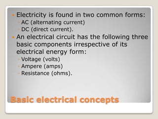
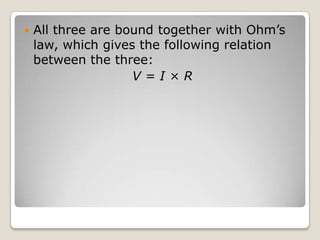
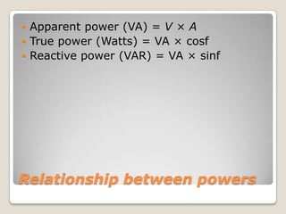
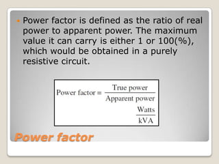


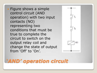
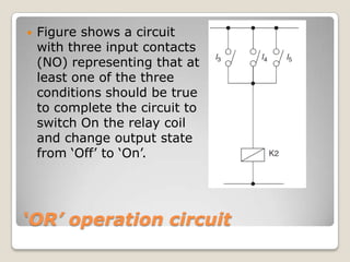
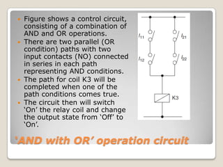


This document provides an overview of basic electrical concepts and principles including AC/DC circuits, voltage, current, resistance, and Ohm's law. It also discusses power in electrical circuits including real, reactive, and apparent power as well as power factor. Additional topics covered include single and three-phase power systems, transformers including types and connections, and electrical devices and symbols used in control circuits. Control circuits are described including AND, OR, and combined logic operations. The document concludes with discussing reading electrical drawings and a workshop practical example.


